EP0497381A1 - Table for the horticulture - Google Patents
Table for the horticulture Download PDFInfo
- Publication number
- EP0497381A1 EP0497381A1 EP92101739A EP92101739A EP0497381A1 EP 0497381 A1 EP0497381 A1 EP 0497381A1 EP 92101739 A EP92101739 A EP 92101739A EP 92101739 A EP92101739 A EP 92101739A EP 0497381 A1 EP0497381 A1 EP 0497381A1
- Authority
- EP
- European Patent Office
- Prior art keywords
- running
- gardening
- table top
- table according
- balls
- Prior art date
- Legal status (The legal status is an assumption and is not a legal conclusion. Google has not performed a legal analysis and makes no representation as to the accuracy of the status listed.)
- Granted
Links
Images

Classifications
-
- A—HUMAN NECESSITIES
- A01—AGRICULTURE; FORESTRY; ANIMAL HUSBANDRY; HUNTING; TRAPPING; FISHING
- A01G—HORTICULTURE; CULTIVATION OF VEGETABLES, FLOWERS, RICE, FRUIT, VINES, HOPS OR SEAWEED; FORESTRY; WATERING
- A01G9/00—Cultivation in receptacles, forcing-frames or greenhouses; Edging for beds, lawn or the like
- A01G9/14—Greenhouses
- A01G9/143—Equipment for handling produce in greenhouses
-
- Y—GENERAL TAGGING OF NEW TECHNOLOGICAL DEVELOPMENTS; GENERAL TAGGING OF CROSS-SECTIONAL TECHNOLOGIES SPANNING OVER SEVERAL SECTIONS OF THE IPC; TECHNICAL SUBJECTS COVERED BY FORMER USPC CROSS-REFERENCE ART COLLECTIONS [XRACs] AND DIGESTS
- Y02—TECHNOLOGIES OR APPLICATIONS FOR MITIGATION OR ADAPTATION AGAINST CLIMATE CHANGE
- Y02A—TECHNOLOGIES FOR ADAPTATION TO CLIMATE CHANGE
- Y02A40/00—Adaptation technologies in agriculture, forestry, livestock or agroalimentary production
- Y02A40/10—Adaptation technologies in agriculture, forestry, livestock or agroalimentary production in agriculture
- Y02A40/25—Greenhouse technology, e.g. cooling systems therefor
Definitions
- the invention relates to a mobile gardening table.
- the tables in garden centers with their relatively large dimensions are used as plant or bedside tables and can only be moved back and forth in one direction and must be moved or lifted out of the greenhouse by lifting devices to change the path.
- the gardening table according to the invention can be moved in the longitudinal direction by means of spherical running bodies (running balls) which can be freely rotated on all sides, on tubular running rails loosely resting on the ground and showing a circular cross section, and at the same time can be moved in the transverse direction with these running rails by these tubular running rails on the Unroll the ground and take the table with the balls rolling on the rails; in this way a very flexible, optional path formation and easily changeable placement of the gardening tables in a greenhouse is possible by simple means.
- running balls spherical running bodies
- the running bodies are arranged at a short distance below the table top, so that the table top can be moved close to the floor and thus has good stability.
- supported additional rails can be arranged at a distance above the table top and continuous rails can be formed when several tables are lined up, which means that further tables can be moved longitudinally in the second level above the lower tables and can be moved transversely with the lower tables on the bottom tubes, which is the task a space-utilizing and optimally movable table group solves.
- the mobile gardening table in the form of a planting or bedside table has a preferably large and preferably rectangular table top (1), under which in each of the four corner areas two table tops (1) forming a running prism (2), preferably on the ground ( 3) exposed tubes (4) moving barrel bodies (5) are arranged.
- Each running body (5) is preferably formed by a running ball rolling on the tube (4)
- the two running balls (5) of each pair of running balls can be mounted on all sides and freely rotatable in a common housing (6) (Fig. 5) or can each be mounted on all sides and freely rotating in a separate housing (7) (Fig. 4).
- the two spherical balls (5) protrude with their calotte area (5a) - rolling part - from one end face (6a, 7a) of the housing or housings (6, 7) and these two end faces (6a, 7a) are at an angle of 45 ° to the table top level and together with the running balls (5) form a 90 ° running prism, which results in a two-point system on the tube (4).
- the common housing (6) which has the two running balls (5) is fastened with a housing flange (6b) and by screws (8) or the like under the table top (1) (Fig. 5) and the two housings (7) of the Running ball pairs are fixed by means of a holder (9) and by screws or the like under the table top (1) (Fig. 4).
- the gardening table can be moved on the one hand in the longitudinal direction of the pipes (4) and can also be traversed with the pipes (4) by the pipes (4 ) roll on the ground (3) and the table rolls with its running bodies on the rotating pipes (4), so that the table is carried along by the pipes (4).
- upright supports (10), preferably one upright support bracket (10) each, are fastened on the table top (1) in the two longitudinal end regions and on these supports (10) are two parallel rods or tubes (11). It defines which running rails form a gardening table that can be moved on it in the second level by means of the running bodies (5).
- One coupling end (12) can be designed as a stepped or conical plug-in pin and the other coupling end (13) as a plug-in sleeve. If the tables are put together (moved together), then the coupling ends (12, 13) of the rods or tubes (11) fit into one another and continuous rails (11) are formed over all the rows of gardening tables, so that by means of a suitable lifting device, such as pallet trucks, forklifts , or the like. One or more gardening tables can be placed on these rails (11) with their running bodies (5) and then at a distance above the lower gardening tables, regardless of the same longitudinal process and the same transverse process.
- Slightly displaceable sliding bodies can also be used as running bodies (5) instead of balls.
- Each running body 5 could also be formed by two rollers arranged one above the other and only effective in one direction of travel.
Landscapes
- Life Sciences & Earth Sciences (AREA)
- Environmental Sciences (AREA)
- Cultivation Receptacles Or Flower-Pots, Or Pots For Seedlings (AREA)
Abstract
Description
Die Erfindung bezieht sich auf einen fahrbaren Gärtnereitisch.The invention relates to a mobile gardening table.
Die in Gärtnereien vorhandenen Tische mit verhältnismäßig großen Ausmaßen werden als Pflanzen- oder Beettische genutzt und sind nur in eine Richtung hin- und herfahrbar und müssen für eine veränderte Wegebildung durch Hubeinrichtungen versetzt oder aus dem Gewächshaus herausgefahren werden.The tables in garden centers with their relatively large dimensions are used as plant or bedside tables and can only be moved back and forth in one direction and must be moved or lifted out of the greenhouse by lifting devices to change the path.
Deshalb ist es Aufgabe der Erfindung, einen Gärtnereitisch dahingehend zu verbessern, daß er durch einfache Mittel sowohl in Längs- als auch in Querrichtung verfahren werden kann und somit in seiner Plazierung und zur gewünschten Wegebildung variabler ist.It is therefore an object of the invention to improve a gardening table in such a way that it can be moved in both the longitudinal and transverse directions by simple means and is therefore more variable in its placement and in the desired path formation.
Diese Aufgabe wird erfindungsgemäß durch die kennzeichnenden Merkmale des Schutzanspruches 1 gelöst, wobei noch die in den einzelnen Unteransprüchen aufgeführten Gestaltungsmerkmale vorteilhafte und förderliche Weiterbildungen der Aufgabenlösung darstellen.This object is achieved according to the invention by the characterizing features of the
Der erfindungsgemäße Gärtnereitisch ist durch allseitig frei drehbare, kugelförmige Laufkörper (Laufkugeln) auf lose auf dem Erdboden aufliegende, rohrförmige, einen kreisförmigen Querschnitt zeigenden Laufschienen in Längsrichtung verfahrbar und gleichzeitig mit diesen Laufschienen in Querrichtung verfahrbar, indem diese rohrförmigen Laufschienen auf dem Erdboden abrollen und den Tisch mit den sich an den Laufschienen abwälzenden Laufkugeln mitnehmen; hierdurch ist durch einfache Mittel eine sehr bewegliche, wahlweise Wegebildung und leicht veränderbare Plazierung der Gärtnereitische in einem Gewächshaus möglich.The gardening table according to the invention can be moved in the longitudinal direction by means of spherical running bodies (running balls) which can be freely rotated on all sides, on tubular running rails loosely resting on the ground and showing a circular cross section, and at the same time can be moved in the transverse direction with these running rails by these tubular running rails on the Unroll the ground and take the table with the balls rolling on the rails; in this way a very flexible, optional path formation and easily changeable placement of the gardening tables in a greenhouse is possible by simple means.
Die Laufkörper sind mit geringem Abstand unter der Tischplatte angeordnet, so daß die Tischplatte bodennah verfahrbar ist und somit in sich eine gute Stabilität hat.The running bodies are arranged at a short distance below the table top, so that the table top can be moved close to the floor and thus has good stability.
Weiterhin lassen sich im Abstand oberhalb der Tischplatte abgestützte zusätzliche Laufschienen anordnen und beim Aneinanderreihen mehrerer Tische somit durchgehende Laufschienen bilden, wodurch oberhalb der unteren Tische weitere Tische in der zweiten Ebene längsverfahrbar und mit den unteren Tischen auf den bodenseitigen Rohren querverfahrbar angeordnet sind, was die Aufgabenstellung einer raumausnutzenden und optimal beweglichen Tischgruppe löst.Furthermore, supported additional rails can be arranged at a distance above the table top and continuous rails can be formed when several tables are lined up, which means that further tables can be moved longitudinally in the second level above the lower tables and can be moved transversely with the lower tables on the bottom tubes, which is the task a space-utilizing and optimally movable table group solves.
Auf den Zeichnungen ist ein Ausführungsbeispiel der Erfindung dargestellt, welches nachfolgend näher erläutert wird. Es zeigt:
- Fig. 1
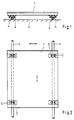
- eine schematische Vorderansicht eines lose auf dem Erdboden aufliegenden Rohres in Rohr-Längsrichtung verfahrbaren Gärtnereitisches, der mit den Rohren auch querverfahrbar ist, und zwar durch Abrollen der Rohre auf dem Erdboden,
- Fig. 2
- eine schematische Draufsicht auf den verfahrbaren Gärtnereitisch,
- Fig. 3
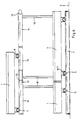
- eine schematische Seitenansicht des Gärtnereitisches,
- Fig. 4
- eine Vorderansicht zweier, den Gärtnereitisch auf einem Rohr verfahrbarer, in je einem Gehäuse drehbar gelagerter, kugelförmiger Laufkörper, die eine prismaförmige Laufrinne ergeben,
- Fig. 5
- eine schematische Vorderansicht eines Gehäuses mit zwei darin drehbaren, kugelförmigen Laufkörpern,
- Fig. 6
- eine schematische Seitenansicht aneinandergereihter Gärtnereitische und auf diesen angeordneten Laufschienen für eine zweite Fahrebene eines oder mehrerer Gärtnereitische.
- Fig. 1
- 1 shows a schematic front view of a garden table which is loosely lying on the ground in the longitudinal direction of the pipe and which can also be traversed with the pipes, namely by rolling the pipes on the ground,
- Fig. 2
- a schematic plan view of the movable gardening table,
- Fig. 3
- a schematic side view of the gardening table,
- Fig. 4
- 2 shows a front view of two spherical running bodies which can be moved on a tube and which can be moved on a tube and which are rotatably mounted in a housing and which result in a prismatic running channel,
- Fig. 5
- 1 shows a schematic front view of a housing with two spherical running bodies rotatable therein,
- Fig. 6
- is a schematic side view of lined up gardening tables and arranged on these rails for a second driving level of one or more gardening tables.
Der fahrbare Gärtnereitisch in Form eines Pflanz- oder Beettisches weist eine vorzugsweise großflächige und vorzugsweise rechteckige Tischplatte (1) auf, unter der in den vier Eckbereichen jeweils zwei ein Laufprisma (2) bildende, die Tischplatte (1) auf von vorzugsweise auf dem Erdboden (3) freiliegenden Rohren gebildeten Laufschienen (4) verfahrende Laufkörper (5) angeordnet sind.The mobile gardening table in the form of a planting or bedside table has a preferably large and preferably rectangular table top (1), under which in each of the four corner areas two table tops (1) forming a running prism (2), preferably on the ground ( 3) exposed tubes (4) moving barrel bodies (5) are arranged.
Jeder Laufkörper (5) ist in bevorzugter Weise von einer sich am Rohr (4) abwälzenden Laufkugel gebildetEach running body (5) is preferably formed by a running ball rolling on the tube (4)
Die beiden Laufkugeln (5) jedes Laufkugelpaares lassen sich in einem gemeinsamen Gehäuse (6) allseitig und frei drehbar lagern (Fig. 5) oder können jeweils in einem eigenen Gehäuse (7) allseitig und frei drehbar gelagert sein (Fig. 4).The two running balls (5) of each pair of running balls can be mounted on all sides and freely rotatable in a common housing (6) (Fig. 5) or can each be mounted on all sides and freely rotating in a separate housing (7) (Fig. 4).
Die beiden Laufkugeln (5) ragen mit ihrem Kalottenbereich (5a) - Abwälzteil - aus je einer Stirnseite (6a, 7a) des bzw. der Gehäuse (6, 7) heraus und diese beiden Stirnseiten (6a, 7a) stehen unter einem Winkel von 45° zur Tischplattenebene und bilden mit den Laufkugeln (5) ein 90°-Laufprisma, welches eine Zweipunktanlage am Rohr (4) ergibt.The two spherical balls (5) protrude with their calotte area (5a) - rolling part - from one end face (6a, 7a) of the housing or housings (6, 7) and these two end faces (6a, 7a) are at an angle of 45 ° to the table top level and together with the running balls (5) form a 90 ° running prism, which results in a two-point system on the tube (4).
Das die beiden Laufkugeln (5) aufweisende gemeinsame Gehäuse (6) ist mit einem Gehäuseflansch (6b) und durch Schrauben (8) od. dgl. unter der Tischplatte (1) befestigt (Fig. 5) und die beiden Gehäuse (7) des Laufkugelpaares sind mittels einer Halterung (9) und durch Schrauben od. dgl. unter der Tischplatte (1) festgelegt (Fig. 4).The common housing (6) which has the two running balls (5) is fastened with a housing flange (6b) and by screws (8) or the like under the table top (1) (Fig. 5) and the two housings (7) of the Running ball pairs are fixed by means of a holder (9) and by screws or the like under the table top (1) (Fig. 4).
Durch die in den vier Eckbereichen der Tischplatte (1) angeordneten Laufkugelpaare (5) läßt sich der Gärtnereitisch einerseits in Längsrichtung der Rohre (4) auf denselben verfahren und kann auch noch zusätzlich mit den Rohren (4) querverfahren werden, indem die Rohre (4) auf dem Erdboden (3) abrollen und der Tisch sich mit seinen Laufkörpern an den sich drehenden Rohren (4) abwälzt, so daß der Tisch von den Rohren (4) mitgenommen wird.Due to the pair of running balls (5) arranged in the four corner areas of the table top (1), the gardening table can be moved on the one hand in the longitudinal direction of the pipes (4) and can also be traversed with the pipes (4) by the pipes (4 ) roll on the ground (3) and the table rolls with its running bodies on the rotating pipes (4), so that the table is carried along by the pipes (4).
Gemäß der ergänzten Ausführung nach Fig. 6 sind auf der Tischplatte (1) in den beiden Längenendbereichen aufrechte Stützen (10), vorzugsweise je ein aufrechter Tragbügel (10) befestigt und auf diesen Stützen (10) sind zwei parallellaufende Stangen oder Rohre (11) festgelegt, welche Laufschienen für einen darauf in der zweiten Ebene mittels der Laufkörper (5) verfahrbaren Gärtnereitisch bilden.According to the supplemented embodiment according to FIG. 6, upright supports (10), preferably one upright support bracket (10) each, are fastened on the table top (1) in the two longitudinal end regions and on these supports (10) are two parallel rods or tubes (11). It defines which running rails form a gardening table that can be moved on it in the second level by means of the running bodies (5).
Dabei kann ein Kupplungsende (12) als abgestufter oder konischer Steckzapfen und das andere Kupplungsende (13) als Steckhülse ausgebildet sein. Werden die Tische aneinandergestellt (zusammengefahren), dann fassen die Kupplungsenden (12, 13) der Stangen oder Rohre (11) ineinander und es werden über sämtliche aneinandergereihte Gärtnereitische durchgehende Laufschienen (11) gebildet, so daß durch eine geeignete Hubvorrichtung, wie Hubwagen, Gabelstapler, od. dgl., ein oder mehrere Gärtnereitische auf diese Laufschienen (11) mit ihren Laufkörpern (5) aufgesetzt und dann mit Abstand oberhalb der unteren Gärtnereitische, unabhängig von denselben längsverfahren und mit denselben querverfahren werden können.One coupling end (12) can be designed as a stepped or conical plug-in pin and the other coupling end (13) as a plug-in sleeve. If the tables are put together (moved together), then the coupling ends (12, 13) of the rods or tubes (11) fit into one another and continuous rails (11) are formed over all the rows of gardening tables, so that by means of a suitable lifting device, such as pallet trucks, forklifts , or the like. One or more gardening tables can be placed on these rails (11) with their running bodies (5) and then at a distance above the lower gardening tables, regardless of the same longitudinal process and the same transverse process.
Als Laufkörper (5) können anstelle von Kugeln auch leicht verschiebliche Gleitkörper eingesetzt werden.Slightly displaceable sliding bodies can also be used as running bodies (5) instead of balls.
Auch könnte jeder Laufkörper 5) von zwei überkreuz ineinander angeordneten und jeweils nur in eine Fahrrichtung wirksam werdenden Rollen gebildet sein.Each running body 5) could also be formed by two rollers arranged one above the other and only effective in one direction of travel.
Claims (10)
Applications Claiming Priority (2)
| Application Number | Priority Date | Filing Date | Title |
|---|---|---|---|
| DE9101146U DE9101146U1 (en) | 1991-02-01 | 1991-02-01 | Gardening table |
| DE9101146U | 1991-02-01 |
Publications (2)
| Publication Number | Publication Date |
|---|---|
| EP0497381A1 true EP0497381A1 (en) | 1992-08-05 |
| EP0497381B1 EP0497381B1 (en) | 1995-08-30 |
Family
ID=6863898
Family Applications (1)
| Application Number | Title | Priority Date | Filing Date |
|---|---|---|---|
| EP92101739A Expired - Lifetime EP0497381B1 (en) | 1991-02-01 | 1992-02-03 | Table for the horticulture |
Country Status (3)
| Country | Link |
|---|---|
| EP (1) | EP0497381B1 (en) |
| DE (2) | DE9101146U1 (en) |
| DK (1) | DK0497381T3 (en) |
Cited By (4)
| Publication number | Priority date | Publication date | Assignee | Title |
|---|---|---|---|---|
| NL9401186A (en) * | 1994-07-19 | 1996-03-01 | Food Processing Systems | Method and assembly for transporting crops from a picking line in a greenhouse to an unloading station |
| NL1011615C2 (en) * | 1999-03-19 | 2000-09-20 | Frans Van Zaal B V | Remotely-controlled powered trolley with friction drive to tubular rails using endless V-belts operating at right angles to one rail |
| NL1019820C2 (en) * | 2001-06-07 | 2002-12-10 | Freek Steenks Service V O F | Device for performing activities in a department store, such as harvesting of cultivated crops, harvesting vehicle for use in such a device and stabilizing element for use in such a harvesting vehicle. |
| EP3673727A4 (en) * | 2017-08-23 | 2021-03-31 | Young-Chai Cho | Plant factory |
Families Citing this family (1)
| Publication number | Priority date | Publication date | Assignee | Title |
|---|---|---|---|---|
| FR2691321B1 (en) * | 1992-05-22 | 1994-08-26 | Gerald Andre | Above ground cultivation system. |
Citations (2)
| Publication number | Priority date | Publication date | Assignee | Title |
|---|---|---|---|---|
| US3915442A (en) * | 1975-03-25 | 1975-10-28 | William F Marantette | Rectangular coordinate positioning system |
| DE2926203A1 (en) * | 1979-06-29 | 1981-01-15 | Josef Schiffer | Plant frost protection for greenhouses - involves dividing wall between two heated areas of greenhouse interior |
-
1991
- 1991-02-01 DE DE9101146U patent/DE9101146U1/en not_active Expired - Lifetime
-
1992
- 1992-02-03 DK DK92101739.8T patent/DK0497381T3/en active
- 1992-02-03 EP EP92101739A patent/EP0497381B1/en not_active Expired - Lifetime
- 1992-02-03 DE DE59203409T patent/DE59203409D1/en not_active Expired - Fee Related
Patent Citations (2)
| Publication number | Priority date | Publication date | Assignee | Title |
|---|---|---|---|---|
| US3915442A (en) * | 1975-03-25 | 1975-10-28 | William F Marantette | Rectangular coordinate positioning system |
| DE2926203A1 (en) * | 1979-06-29 | 1981-01-15 | Josef Schiffer | Plant frost protection for greenhouses - involves dividing wall between two heated areas of greenhouse interior |
Cited By (5)
| Publication number | Priority date | Publication date | Assignee | Title |
|---|---|---|---|---|
| NL9401186A (en) * | 1994-07-19 | 1996-03-01 | Food Processing Systems | Method and assembly for transporting crops from a picking line in a greenhouse to an unloading station |
| NL1011615C2 (en) * | 1999-03-19 | 2000-09-20 | Frans Van Zaal B V | Remotely-controlled powered trolley with friction drive to tubular rails using endless V-belts operating at right angles to one rail |
| NL1019820C2 (en) * | 2001-06-07 | 2002-12-10 | Freek Steenks Service V O F | Device for performing activities in a department store, such as harvesting of cultivated crops, harvesting vehicle for use in such a device and stabilizing element for use in such a harvesting vehicle. |
| WO2002098207A1 (en) * | 2001-06-07 | 2002-12-12 | Freek Steenks Service V.O.F. | Equipment for a glasshouse, harvesting vehicle for use with such an equipment, and stabilizing element for such a vehicle |
| EP3673727A4 (en) * | 2017-08-23 | 2021-03-31 | Young-Chai Cho | Plant factory |
Also Published As
| Publication number | Publication date |
|---|---|
| DE9101146U1 (en) | 1991-05-02 |
| DE59203409D1 (en) | 1995-10-05 |
| DK0497381T3 (en) | 1996-01-15 |
| EP0497381B1 (en) | 1995-08-30 |
Similar Documents
| Publication | Publication Date | Title |
|---|---|---|
| EP0704389B1 (en) | Device for storing glassplates or insulating glasspanes | |
| DE3340322C2 (en) | Extendable continuous conveyor | |
| EP0497381B1 (en) | Table for the horticulture | |
| DE69311659T2 (en) | Positioning device for cutting tiles along a diagonal | |
| DE3610130C2 (en) | Gripping device | |
| EP0163935A1 (en) | Control device for nuclear reactor fuel pins | |
| DE3505200C2 (en) | Drive device for parking facilities for motor vehicles | |
| DE3115479A1 (en) | Transfer arrangement for a rack-loading appliance | |
| DE908305C (en) | Mechanism for measuring the wall thickness of pipe bodies | |
| EP0132448B1 (en) | Table with adjustable table top | |
| DE2942743A1 (en) | CULTURAL TABLE FOR GARDENING COMPANIES | |
| AT330494B (en) | SOIL TILLING MACHINE | |
| DE3313754A1 (en) | Positioning device for a remote-controlled shelf-loading appliance in rack stores | |
| EP0100491A2 (en) | Dental chair | |
| DE2905948A1 (en) | Profiling machine for sheet metal strips - has side guide track with movable carriage assembly | |
| DE1217047B (en) | Alignment device for motor vehicles in front of a motor vehicle parking space | |
| DE2558637C2 (en) | Device for horizontal positioning of battery-operated electric vehicles at battery changing stations | |
| DE822534C (en) | Straightening device on rolling mills with straightening strips arranged to the side of the roller table | |
| DE2304140A1 (en) | DEVICE FOR STORING ROD-SHAPED MATERIALS | |
| DE8021366U1 (en) | DEVICE FOR HOLDING TIRE-SHAPED JEWELERY | |
| DE401507C (en) | Mobile support for nozzle pipes of rain devices | |
| AT313172B (en) | Device for the automatic filling of potato boxes in warehouses for potatoes | |
| DE928609C (en) | Transport trolley for use between rows of fruit beds | |
| DD145905A1 (en) | DEVICE FOR TRANSPORTING TUBULAR TREATMENT GOODS | |
| DE2558637B1 (en) | Device for horizontal positioning of battery-operated electric vehicles at battery changing stations |
Legal Events
| Date | Code | Title | Description |
|---|---|---|---|
| PUAI | Public reference made under article 153(3) epc to a published international application that has entered the european phase |
Free format text: ORIGINAL CODE: 0009012 |
|
| AK | Designated contracting states |
Kind code of ref document: A1 Designated state(s): BE DE DK FR IT NL |
|
| 17P | Request for examination filed |
Effective date: 19930204 |
|
| 17Q | First examination report despatched |
Effective date: 19940303 |
|
| GRAA | (expected) grant |
Free format text: ORIGINAL CODE: 0009210 |
|
| AK | Designated contracting states |
Kind code of ref document: B1 Designated state(s): BE DE DK FR IT NL |
|
| PG25 | Lapsed in a contracting state [announced via postgrant information from national office to epo] |
Ref country code: IT Free format text: LAPSE BECAUSE OF FAILURE TO SUBMIT A TRANSLATION OF THE DESCRIPTION OR TO PAY THE FEE WITHIN THE PRE;WARNING: LAPSES OF ITALIAN PATENTS WITH EFFECTIVE DATE BEFORE 2007 MAY HAVE OCCURRED AT ANY TIME BEFORE 2007. THE CORRECT EFFECTIVE DATE MAY BE DIFFERENT FROM THE ONE RECORDED.SCRIBED TIME-LIMIT Effective date: 19950830 |
|
| REF | Corresponds to: |
Ref document number: 59203409 Country of ref document: DE Date of ref document: 19951005 |
|
| ET | Fr: translation filed | ||
| REG | Reference to a national code |
Ref country code: DK Ref legal event code: T3 |
|
| PGFP | Annual fee paid to national office [announced via postgrant information from national office to epo] |
Ref country code: DE Payment date: 19960227 Year of fee payment: 5 |
|
| PGFP | Annual fee paid to national office [announced via postgrant information from national office to epo] |
Ref country code: DK Payment date: 19960228 Year of fee payment: 5 Ref country code: FR Payment date: 19960228 Year of fee payment: 5 |
|
| PGFP | Annual fee paid to national office [announced via postgrant information from national office to epo] |
Ref country code: BE Payment date: 19960229 Year of fee payment: 5 Ref country code: NL Payment date: 19960229 Year of fee payment: 5 |
|
| PLBE | No opposition filed within time limit |
Free format text: ORIGINAL CODE: 0009261 |
|
| STAA | Information on the status of an ep patent application or granted ep patent |
Free format text: STATUS: NO OPPOSITION FILED WITHIN TIME LIMIT |
|
| 26N | No opposition filed | ||
| PG25 | Lapsed in a contracting state [announced via postgrant information from national office to epo] |
Ref country code: DK Effective date: 19970203 |
|
| REG | Reference to a national code |
Ref country code: DK Ref legal event code: EBP |
|
| PG25 | Lapsed in a contracting state [announced via postgrant information from national office to epo] |
Ref country code: BE Effective date: 19970228 |
|
| BERE | Be: lapsed |
Owner name: MARX HUBERT Effective date: 19970228 |
|
| PG25 | Lapsed in a contracting state [announced via postgrant information from national office to epo] |
Ref country code: NL Effective date: 19970901 |
|
| PG25 | Lapsed in a contracting state [announced via postgrant information from national office to epo] |
Ref country code: FR Effective date: 19971030 |
|
| PG25 | Lapsed in a contracting state [announced via postgrant information from national office to epo] |
Ref country code: DE Effective date: 19971101 |
|
| NLV4 | Nl: lapsed or anulled due to non-payment of the annual fee |
Effective date: 19970901 |
|
| REG | Reference to a national code |
Ref country code: FR Ref legal event code: ST |