EP0496669B1 - Dispositif pour la pose d'un fil de résistance sous une forme onduleuse sur la pellicule intercalaire thermoplastique d'un vitrage feuilleté - Google Patents
Dispositif pour la pose d'un fil de résistance sous une forme onduleuse sur la pellicule intercalaire thermoplastique d'un vitrage feuilleté Download PDFInfo
- Publication number
- EP0496669B1 EP0496669B1 EP92400159A EP92400159A EP0496669B1 EP 0496669 B1 EP0496669 B1 EP 0496669B1 EP 92400159 A EP92400159 A EP 92400159A EP 92400159 A EP92400159 A EP 92400159A EP 0496669 B1 EP0496669 B1 EP 0496669B1
- Authority
- EP
- European Patent Office
- Prior art keywords
- wire
- wheel
- toothed wheels
- deforming
- support
- Prior art date
- Legal status (The legal status is an assumption and is not a legal conclusion. Google has not performed a legal analysis and makes no representation as to the accuracy of the status listed.)
- Expired - Lifetime
Links
- 229920001169 thermoplastic Polymers 0.000 title claims abstract description 8
- 239000004416 thermosoftening plastic Substances 0.000 title claims abstract description 8
- 238000005096 rolling process Methods 0.000 claims abstract description 8
- 230000002093 peripheral effect Effects 0.000 claims description 10
- 238000003825 pressing Methods 0.000 claims description 3
- 238000010438 heat treatment Methods 0.000 claims description 2
- 238000004519 manufacturing process Methods 0.000 abstract description 3
- 239000004020 conductor Substances 0.000 description 2
- 238000010276 construction Methods 0.000 description 2
- 238000005485 electric heating Methods 0.000 description 2
- 238000009434 installation Methods 0.000 description 2
- 125000006850 spacer group Chemical group 0.000 description 2
- 230000002411 adverse Effects 0.000 description 1
- 230000015556 catabolic process Effects 0.000 description 1
- 238000006073 displacement reaction Methods 0.000 description 1
- 230000000694 effects Effects 0.000 description 1
- 238000003780 insertion Methods 0.000 description 1
- 230000037431 insertion Effects 0.000 description 1
- 230000002687 intercalation Effects 0.000 description 1
- 238000009830 intercalation Methods 0.000 description 1
- 239000011229 interlayer Substances 0.000 description 1
- 239000005340 laminated glass Substances 0.000 description 1
- 239000010410 layer Substances 0.000 description 1
- 238000012423 maintenance Methods 0.000 description 1
- 239000002245 particle Substances 0.000 description 1
- 239000004033 plastic Substances 0.000 description 1
- 229920003023 plastic Polymers 0.000 description 1
- 229920002037 poly(vinyl butyral) polymer Polymers 0.000 description 1
- 239000012815 thermoplastic material Substances 0.000 description 1
- 238000003466 welding Methods 0.000 description 1
Images
Classifications
-
- B—PERFORMING OPERATIONS; TRANSPORTING
- B29—WORKING OF PLASTICS; WORKING OF SUBSTANCES IN A PLASTIC STATE IN GENERAL
- B29C—SHAPING OR JOINING OF PLASTICS; SHAPING OF MATERIAL IN A PLASTIC STATE, NOT OTHERWISE PROVIDED FOR; AFTER-TREATMENT OF THE SHAPED PRODUCTS, e.g. REPAIRING
- B29C70/00—Shaping composites, i.e. plastics material comprising reinforcements, fillers or preformed parts, e.g. inserts
- B29C70/68—Shaping composites, i.e. plastics material comprising reinforcements, fillers or preformed parts, e.g. inserts by incorporating or moulding on preformed parts, e.g. inserts or layers, e.g. foam blocks
- B29C70/82—Forcing wires, nets or the like partially or completely into the surface of an article, e.g. by cutting and pressing
-
- B—PERFORMING OPERATIONS; TRANSPORTING
- B32—LAYERED PRODUCTS
- B32B—LAYERED PRODUCTS, i.e. PRODUCTS BUILT-UP OF STRATA OF FLAT OR NON-FLAT, e.g. CELLULAR OR HONEYCOMB, FORM
- B32B17/00—Layered products essentially comprising sheet glass, or glass, slag, or like fibres
- B32B17/06—Layered products essentially comprising sheet glass, or glass, slag, or like fibres comprising glass as the main or only constituent of a layer, next to another layer of a specific material
- B32B17/10—Layered products essentially comprising sheet glass, or glass, slag, or like fibres comprising glass as the main or only constituent of a layer, next to another layer of a specific material of synthetic resin
- B32B17/10005—Layered products essentially comprising sheet glass, or glass, slag, or like fibres comprising glass as the main or only constituent of a layer, next to another layer of a specific material of synthetic resin laminated safety glass or glazing
- B32B17/10165—Functional features of the laminated safety glass or glazing
- B32B17/10376—Laminated safety glass or glazing containing metal wires
-
- H—ELECTRICITY
- H05—ELECTRIC TECHNIQUES NOT OTHERWISE PROVIDED FOR
- H05B—ELECTRIC HEATING; ELECTRIC LIGHT SOURCES NOT OTHERWISE PROVIDED FOR; CIRCUIT ARRANGEMENTS FOR ELECTRIC LIGHT SOURCES, IN GENERAL
- H05B3/00—Ohmic-resistance heating
- H05B3/84—Heating arrangements specially adapted for transparent or reflecting areas, e.g. for demisting or de-icing windows, mirrors or vehicle windshields
- H05B3/86—Heating arrangements specially adapted for transparent or reflecting areas, e.g. for demisting or de-icing windows, mirrors or vehicle windshields the heating conductors being embedded in the transparent or reflecting material
-
- B—PERFORMING OPERATIONS; TRANSPORTING
- B29—WORKING OF PLASTICS; WORKING OF SUBSTANCES IN A PLASTIC STATE IN GENERAL
- B29C—SHAPING OR JOINING OF PLASTICS; SHAPING OF MATERIAL IN A PLASTIC STATE, NOT OTHERWISE PROVIDED FOR; AFTER-TREATMENT OF THE SHAPED PRODUCTS, e.g. REPAIRING
- B29C65/00—Joining or sealing of preformed parts, e.g. welding of plastics materials; Apparatus therefor
- B29C65/02—Joining or sealing of preformed parts, e.g. welding of plastics materials; Apparatus therefor by heating, with or without pressure
- B29C65/44—Joining a heated non plastics element to a plastics element
-
- B—PERFORMING OPERATIONS; TRANSPORTING
- B29—WORKING OF PLASTICS; WORKING OF SUBSTANCES IN A PLASTIC STATE IN GENERAL
- B29C—SHAPING OR JOINING OF PLASTICS; SHAPING OF MATERIAL IN A PLASTIC STATE, NOT OTHERWISE PROVIDED FOR; AFTER-TREATMENT OF THE SHAPED PRODUCTS, e.g. REPAIRING
- B29C66/00—General aspects of processes or apparatus for joining preformed parts
- B29C66/01—General aspects dealing with the joint area or with the area to be joined
- B29C66/05—Particular design of joint configurations
- B29C66/10—Particular design of joint configurations particular design of the joint cross-sections
- B29C66/11—Joint cross-sections comprising a single joint-segment, i.e. one of the parts to be joined comprising a single joint-segment in the joint cross-section
- B29C66/112—Single lapped joints
- B29C66/1122—Single lap to lap joints, i.e. overlap joints
-
- B—PERFORMING OPERATIONS; TRANSPORTING
- B29—WORKING OF PLASTICS; WORKING OF SUBSTANCES IN A PLASTIC STATE IN GENERAL
- B29C—SHAPING OR JOINING OF PLASTICS; SHAPING OF MATERIAL IN A PLASTIC STATE, NOT OTHERWISE PROVIDED FOR; AFTER-TREATMENT OF THE SHAPED PRODUCTS, e.g. REPAIRING
- B29C66/00—General aspects of processes or apparatus for joining preformed parts
- B29C66/01—General aspects dealing with the joint area or with the area to be joined
- B29C66/05—Particular design of joint configurations
- B29C66/20—Particular design of joint configurations particular design of the joint lines, e.g. of the weld lines
- B29C66/22—Particular design of joint configurations particular design of the joint lines, e.g. of the weld lines said joint lines being in the form of recurring patterns
- B29C66/221—Particular design of joint configurations particular design of the joint lines, e.g. of the weld lines said joint lines being in the form of recurring patterns being in the form of a sinusoidal wave
-
- B—PERFORMING OPERATIONS; TRANSPORTING
- B29—WORKING OF PLASTICS; WORKING OF SUBSTANCES IN A PLASTIC STATE IN GENERAL
- B29C—SHAPING OR JOINING OF PLASTICS; SHAPING OF MATERIAL IN A PLASTIC STATE, NOT OTHERWISE PROVIDED FOR; AFTER-TREATMENT OF THE SHAPED PRODUCTS, e.g. REPAIRING
- B29C66/00—General aspects of processes or apparatus for joining preformed parts
- B29C66/70—General aspects of processes or apparatus for joining preformed parts characterised by the composition, physical properties or the structure of the material of the parts to be joined; Joining with non-plastics material
- B29C66/73—General aspects of processes or apparatus for joining preformed parts characterised by the composition, physical properties or the structure of the material of the parts to be joined; Joining with non-plastics material characterised by the intensive physical properties of the material of the parts to be joined, by the optical properties of the material of the parts to be joined, by the extensive physical properties of the parts to be joined, by the state of the material of the parts to be joined or by the material of the parts to be joined being a thermoplastic or a thermoset
- B29C66/739—General aspects of processes or apparatus for joining preformed parts characterised by the composition, physical properties or the structure of the material of the parts to be joined; Joining with non-plastics material characterised by the intensive physical properties of the material of the parts to be joined, by the optical properties of the material of the parts to be joined, by the extensive physical properties of the parts to be joined, by the state of the material of the parts to be joined or by the material of the parts to be joined being a thermoplastic or a thermoset characterised by the material of the parts to be joined being a thermoplastic or a thermoset
- B29C66/7392—General aspects of processes or apparatus for joining preformed parts characterised by the composition, physical properties or the structure of the material of the parts to be joined; Joining with non-plastics material characterised by the intensive physical properties of the material of the parts to be joined, by the optical properties of the material of the parts to be joined, by the extensive physical properties of the parts to be joined, by the state of the material of the parts to be joined or by the material of the parts to be joined being a thermoplastic or a thermoset characterised by the material of the parts to be joined being a thermoplastic or a thermoset characterised by the material of at least one of the parts being a thermoplastic
-
- B—PERFORMING OPERATIONS; TRANSPORTING
- B29—WORKING OF PLASTICS; WORKING OF SUBSTANCES IN A PLASTIC STATE IN GENERAL
- B29C—SHAPING OR JOINING OF PLASTICS; SHAPING OF MATERIAL IN A PLASTIC STATE, NOT OTHERWISE PROVIDED FOR; AFTER-TREATMENT OF THE SHAPED PRODUCTS, e.g. REPAIRING
- B29C66/00—General aspects of processes or apparatus for joining preformed parts
- B29C66/70—General aspects of processes or apparatus for joining preformed parts characterised by the composition, physical properties or the structure of the material of the parts to be joined; Joining with non-plastics material
- B29C66/74—Joining plastics material to non-plastics material
- B29C66/742—Joining plastics material to non-plastics material to metals or their alloys
-
- B—PERFORMING OPERATIONS; TRANSPORTING
- B29—WORKING OF PLASTICS; WORKING OF SUBSTANCES IN A PLASTIC STATE IN GENERAL
- B29C—SHAPING OR JOINING OF PLASTICS; SHAPING OF MATERIAL IN A PLASTIC STATE, NOT OTHERWISE PROVIDED FOR; AFTER-TREATMENT OF THE SHAPED PRODUCTS, e.g. REPAIRING
- B29C66/00—General aspects of processes or apparatus for joining preformed parts
- B29C66/80—General aspects of machine operations or constructions and parts thereof
- B29C66/83—General aspects of machine operations or constructions and parts thereof characterised by the movement of the joining or pressing tools
- B29C66/834—General aspects of machine operations or constructions and parts thereof characterised by the movement of the joining or pressing tools moving with the parts to be joined
- B29C66/8341—Roller, cylinder or drum types; Band or belt types; Ball types
- B29C66/83411—Roller, cylinder or drum types
-
- H—ELECTRICITY
- H05—ELECTRIC TECHNIQUES NOT OTHERWISE PROVIDED FOR
- H05B—ELECTRIC HEATING; ELECTRIC LIGHT SOURCES NOT OTHERWISE PROVIDED FOR; CIRCUIT ARRANGEMENTS FOR ELECTRIC LIGHT SOURCES, IN GENERAL
- H05B2203/00—Aspects relating to Ohmic resistive heating covered by group H05B3/00
- H05B2203/014—Heaters using resistive wires or cables not provided for in H05B3/54
-
- Y—GENERAL TAGGING OF NEW TECHNOLOGICAL DEVELOPMENTS; GENERAL TAGGING OF CROSS-SECTIONAL TECHNOLOGIES SPANNING OVER SEVERAL SECTIONS OF THE IPC; TECHNICAL SUBJECTS COVERED BY FORMER USPC CROSS-REFERENCE ART COLLECTIONS [XRACs] AND DIGESTS
- Y10—TECHNICAL SUBJECTS COVERED BY FORMER USPC
- Y10T—TECHNICAL SUBJECTS COVERED BY FORMER US CLASSIFICATION
- Y10T29/00—Metal working
- Y10T29/49—Method of mechanical manufacture
- Y10T29/49002—Electrical device making
- Y10T29/49082—Resistor making
- Y10T29/49083—Heater type
-
- Y—GENERAL TAGGING OF NEW TECHNOLOGICAL DEVELOPMENTS; GENERAL TAGGING OF CROSS-SECTIONAL TECHNOLOGIES SPANNING OVER SEVERAL SECTIONS OF THE IPC; TECHNICAL SUBJECTS COVERED BY FORMER USPC CROSS-REFERENCE ART COLLECTIONS [XRACs] AND DIGESTS
- Y10—TECHNICAL SUBJECTS COVERED BY FORMER USPC
- Y10T—TECHNICAL SUBJECTS COVERED BY FORMER US CLASSIFICATION
- Y10T29/00—Metal working
- Y10T29/51—Plural diverse manufacturing apparatus including means for metal shaping or assembling
- Y10T29/5187—Wire working
Definitions
- the present invention relates to a device for laying and fixing a resistance wire on a thermoplastic support film for the production of an electrically heatable laminated glazing, comprising a heated pressure roller rolling on the support film and welding the resistance wire to this film, a support for a coil of wire and a wire guide device.
- the wire is brought above the support film by a laying device in the form of a guide pad animated by a movement transverse and is simultaneously embedded in the film (document DE-AS 16 79 930).
- the wavy shape of the wire is in this case produced directly on the surface of the film and the wire must, at the time of its installation, be fixed sufficiently under penalty of being detached immediately under the effect of the tension created by the device. deposit. This is why the wire laying speed is subject to narrow limits.
- toothed rings arranged obliquely to each other roll on the film, receive the wire between their teeth which approach the one from the other and deform the wire in a wavy way immediately before laying it on the support film, then press it into the support film either themselves or using a pressure wheel provided with pressing fingers engaging between the teeth (document DE-AS-22 04 939) .
- These devices certainly allow a high laying speed, but are very sensitive to maintenance, because particles of the thermoplastic support film easily adhere to the teeth and the pressing fingers engaging in the surface of the support film and adversely affect the operating capacity of the device.
- This prior application describes a device for laying and fixing a resistance wire on a thermoplastic support film for the production of an electrically heatable laminated glazing, comprising a heating pressure roller rolling on the support film and driving the resistance wire in this film, a support for a wire reel and a wire guide device, and in which, between the support for the wire reel and the heated pressure roller is installed a pair of toothed wheels which mesh 'the other and which deform the wire, at least one of these toothed wheels being driven by the pressure roller rolling on the support film.
- the invention aims to provide a device for laying electrical resistance wires in a wavy form on the surface of the thermoplastic interlayer of a laminated glazing, which allows on the one hand, a high installation speed which is, on the other hand, simple and robust in construction and not very prone to breakdowns.
- this object is achieved in particular by the fact that between the support for the coil of wire and the heated pressure roller is installed a pair of toothed wheels which mesh with one another and which deform the wire , at least one of these toothed wheels being driven by the pressure roller rolling on the film, and, between the pressure roller and the pair of toothed wheels deforming the wire is interposed a gear whose reduction ratio is chosen such that the peripheral speed of the pressure roller and thus the laying speed of the pre-shaped wire are greater than the peripheral speed of the toothed wheels deforming the wire.
- the wire is held under a slight tension, over the distance between the pair of deforming toothed wheels and the laying point below the pressure roller, which makes it possible to avoid uncontrolled slippage of the wire.
- the wire is deformed in a deformation device preceding the pressure roller and the pressure roller is used simply to drive the pre-shaped wire into the surface of the film.
- the width of the pressure roller is greater than the amplitude of the pre-shaped wire, so that, thanks to the large pressure surface which, moreover, can be of a smooth configuration, the pressure roller does not sink into the film and that this film is not damaged.
- the drive of the toothed wheels deforming the wire by the pressure roller guarantees that the wire is laid on the support film in a constant form in a manner entirely independent of the laying speed.
- the pre-shaped wire can in fact be drawn more or less strongly, so that the amplitude of the pre-shaped wire is all the smaller the smaller the peripheral speed of the deforming gearwheels relative to the peripheral speed of the pressure roller.
- thermoplastic support film 1, on which the resistance wire 2 is laid in a wavy form is usually made of polyvinyl butyral.
- the laying device is guided under a light pressure on the support film 1 immobilized on a work table, or the support film 1 runs on a mobile support below the laying device mounted fixed , in which case it goes without saying that care must be taken that the delivery device exerts a corresponding pressure on the film.
- These means which ensure the positioning of the film and the laying device as well as the relative displacement necessary between the laying device and the support film, are known per se, so that the description may be limited to the construction of the laying device.
- Each wire laying device comprises a support arm 6 which is fixed to the crosspiece 5 and which, at its lower end, carries a swivel piece 7 in which the shaft 8 is mounted for rotation.
- the pressure roller 10 On one side of the journal part 7, after the insertion of a spacer ring 9, the pressure roller 10 is wedged, while on the other side of the journal part 7, also after intercalation of a spacer ring 9, a right gear 11 is wedged which, consequently, rotates jointly with the pressure roller 10.
- the pressure roller 10 has a smooth cylindrical surface and its width is greater than the amplitude of the wavy wire 2.
- journaling part 7 an electric heating resistor 14 by means of which the pressure roller 10 is heated to such an extent that at the point of contact of the pressure roller 10 with the support film 1, the thermoplastic material of the film is heated to the point that the wire 2 laid in a wavy form adheres to the softened surface of the film.
- the square-shaped journal part 16 is mounted above the pressure roller 10 and the straight gear 11, on the support arm 6.
- the projecting wing 16a forms the bearing for the shaft 17 parallel to the shaft 8, on which is fixed, above the right gear 11, a right gear 18 which meshes the wheel 11.
- a conical gear 19 is mounted on the shaft 17.
- This bevel gear 19 is engaged with a bevel gear 20 which is rigidly connected to a spur gear 21.
- the axle of rotation 24 for the bevel gear 20 and for the right gear 21 is perpendicular to the axis of rotation 17 and is rotatably mounted in the swivel piece 16.
- the right gear 21 meshes with a straight gear 22 arranged next to it and forms therewith the pair of toothed wheels used for the deformation of the wire.
- the segments of these two toothed wheels 21, 22, which are engaged with each other are located in the area above the pressure roller 10, so that the wire 2 deformed in an undulating fashion, after its exit of the gear wheel engagement zone, applies to the cylindrical surface of the pressure roller 10.
- the straight teeth 11, 18 are dimensioned in such a way that the peripheral speed of the toothed wheels 21, 22 amounts to approximately 80% of the peripheral speed of the pressure roller 10.
- the reduction ratio can be modified so that, for example, the amplitude of the wire 2 laid in a wavy form can be modified.
- a console 26 which carries a support pin 27 for the wire spool 28.
- the console 26 further carries a wire guide eyelet 30 for wire 2 unwound from the coil.
- the electric heating resistor 14 is supplied with electric current via the supply conductors 32, 33 which extend inside the support arm 6.
- the supply conductors 32, 33 terminate at connection terminals 34 to which the cables 35 connected from the power supply device are connected.
Landscapes
- Chemical & Material Sciences (AREA)
- Engineering & Computer Science (AREA)
- Composite Materials (AREA)
- Mechanical Engineering (AREA)
- Laminated Bodies (AREA)
- Joining Of Glass To Other Materials (AREA)
- Specific Sealing Or Ventilating Devices For Doors And Windows (AREA)
- Lining Or Joining Of Plastics Or The Like (AREA)
Description
- La présente invention concerne un dispositif pour la pose et la fixation d'un fil de résistance sur une pellicule de support thermoplastique en vue de la fabrication d'un vitrage feuilleté chauffable électriquement, comportant un galet presseur chauffé roulant sur la pellicule de support et soudant le fil de résistance à cette pellicule, un support pour une bobine de fil et un dispositif guide-fil.
- Dans le cas d'un dispositif connu de ce type qui sert à la pose du fil d'antenne sur la couche intercalaire en matière plastique d'un pare-brise en verre feuilleté, le fil est appliqué en ligne droite sur la pellicule de support (document DE-AS 20 43 706). Ce dispositif connu ne convient pas pour appliquer un fil de résistance électrique sous une forme onduleuse sur la pellicule de support.
- Dans un dispositif connu pour l'application d'un fil de résistance sous une forme onduleuse, le fil est amené au-dessus de la pellicule de support par un dispositif de pose ayant la forme d'un patin de guidage animé d'un mouvement transversal périodique et est en même temps enfoncé dans la pellicule (document DE-AS 16 79 930). La forme onduleuse du fil est dans ce cas produite directement sur la surface de la pellicule et le fil doit, à l'instant de sa pose, être fixé suffisamment sous peine de se détacher aussitôt sous l'effet de la tension créée par le dispositif de pose. C'est pourquoi, la vitesse de pose du fil est soumise à des limites étroites.
- Dans d'autres dispositifs connus pour la pose d'un fil de résistance sous une forme onduleuse, des couronnes dentées disposées obliquement l'une par rapport à l'autre roulent sur la pellicule, reçoivent le fil entre leurs dents qui se rapprochent l'une de l'autre et déforment le fil de manière onduleuse immédiatement avant sa pose sur la pellicule de support, puis l'enfoncent dans la pellicule de support soit elles-mêmes, soit à l'aide d'une roue de pression pourvue de doigts presseurs s'engageant entre les dents (document DE-AS-22 04 939). Ces dispositifs permettent certes une vitesse de pose élevée, mais sont très sensibles à l'entretien, car des particules de la pellicule de support thermoplastique adhèrent facilement aux dents et aux doigts presseurs s'engageant dans la surface de la pellicule de support et affectent défavorablement la capacité de fonctionnement du dispositif.
- La demande de brevet antérieure EP-A-O 443 691 est comprise dans l'état de la technique selon l'article 54 paragraphe 3 de la convention sur le brevet européen. Cette demande est non opposable pour l'appréciation de l'activité inventive.
- Cette demande antérieure décrit un dispositif pour la pose et la fixation d'un fil de résistance sur une pellicule de support thermoplastique en vue de la fabrication d'un vitrage feuilleté chauffable électriquement, comportant un galet presseur chauffant roulant sur la pellicule de support et enfonçant le fil de résistance dans cette pellicule, un support pour une bobine de fil et un dispositif guide fil, et dans lequel, entre le support pour la bobine de fil et le galet presseur chauffé est installée une paire de roues dentées qui s'engrènent l'une l'autre et qui déforment le fil, au moins une de ces roues dentées étant entraînée par le galet presseur roulant sur la pellicule de support.
- Au départ de cet état de la technique, l'invention a pour but de procurer un dispositif pour la pose de fils de résistance électrique sous une forme onduleuse sur la surface de la couche intercalaire thermoplastique d'un vitrage feuilleté, qui permette, d'une part, une vitesse de pose élevée et qui soit, d'autre part, simple et robuste de construction et peu sujet aux pannes.
- Suivant l'invention, ce but est réalisé notamment par le fait qu'entre le support pour la bobine de fil et le galet presseur chauffé est installé une paire de roues dentées qui s'engrènent l'une l'autre et qui déforment le fil, au moins une de ces roues dentées étant entraînée par le galet presseur roulant sur la pellicule, et, entre le galet presseur et la paire de roues dentées déformant le fil est intercalé un engrenage dont le rapport de réduction est choisi tel que la vitesse périphérique du galet presseur et ainsi la vitesse de pose du fil préfaçonné soient supérieures à la vitesse périphérique des roues dentées déformant le fil. De cette façon, le fil est maintenu sous une légère tension, sur la distance comprise entre la paire de roues dentées déformantes et le point de pose en dessous du galet presseur, ce qui permet d'éviter des glissements incontrôlés du fil.
- Dans le cas du dispositif conforme à l'invention, la déformation du fil s'effectue dans un dispositif de déformation précédent le galet presseur et le galet presseur sert simplement à enfoncer le fil préfaçonné dans la surface de la pellicule. La largeur du galet presseur est supérieure à l'amplitude du fil préfaçonné, de sorte que, grâce à la surface de pression large qui, par ailleurs, peut être d'une configuration lisse, le galet presseur ne s'enfonce pas dans la pellicule et que cette pellicule n'est pas abîmée. L'entraînement des roues dentées déformant le fil par le galet presseur garantit que le fil soit posé sur la pellicule de support sous une forme constante d'une manière entièrement indépendante de la vitesse de pose.
- En remplaçant les roues dentées déterminant le rapport de réduction de l'engrenage par d'autres roues dentées déterminant un autre rapport de réduction, on peut de cette manière simple modifier dans de larges limites l'amplitude du fil posé sur la pellicule de support. Le fil préfaçonné peut en effet être étiré plus ou moins fortement, de sorte que l'amplitude du fil préfaçonné est d'autant plus petite que la vitesse périphérique des roues dentées déformantes est petite par rapport à la vitesse périphérique du galet presseur.
- Un exemple de réalisation préféré du dispositif conforme à l'invention sera décrit ci-après en détail, avec référence aux dessins annexés, dans lesquels :
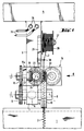
- La fig. 1 est une vue en élévation de face d'un dispositif de pose de fil conforme à l'invention, et
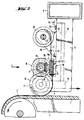
- La fig. 2 est une vue en élévation de côté du dispositif de pose de fil.
- La pellicule de support thermoplastique 1, sur laquelle le fil de résistance 2 est posé sous une forme onduleuse, est habituellement en butyral polyvinylique. Pour la pose du fil de résistance, le dispositif de pose est guidé sous une légère pression sur la pellicule de support 1 immobilisée sur une table de travail, ou la pellicule de support 1 défile sur un support mobile en dessous du dispositif de pose monté fixe, auquel cas il va de soi qu'il faut veiller à ce que le dispositif de pose exerce une pression correspondante sur la pellicule. Ces moyens qui assurent le positionnement de la pellicule et du dispositif de pose ainsi que le déplacement relatif nécessaire entre le dispositif de pose et la pellicule de support, sont connus en soi, de sorte que la description peut se limiter à la construction du dispositif de pose.
- Sur la traverse 5, qui est installée au-dessus de la table d'appui 4 pour la pellicule de support 1, sont montés un ou plusieurs dispositifs de pose de fil. Chaque dispositif de pose de fil comprend un bras de support 6 qui est fixé à la traverse 5 et qui, à son extrémité inférieure, porte une pièce de tourillonnement 7 dans laquelle l'arbre 8 est monté à rotation. Sur cet arbre 8, d'un côté de la pièce de tourillonnement 7, après intercalation d'une bague d'espacement 9, est calé le galet presseur 10, tandis que de l'autre côté de la pièce de tourillonnement 7, également après intercalation d'une bague d'espacement 9, est calée une roue à denture droite 11 qui, en conséquence, tourne conjointement avec le galet presseur 10. Le galet presseur 10 présente une surface cylindrique lisse et sa largeur est supérieure à l'amplitude du fil onduleux 2. Dans la pièce de tourillonnement 7 est installée une résistance chauffante électrique 14 au moyen de laquelle le galet presseur 10 est chauffé dans une mesure telle qu'à l'endroit de contact du galet presseur 10 avec la pellicule de support 1, la matière thermoplastique de la pellicule soit chauffée au point que le fil 2 posé sous une forme onduleuse adhère à la surface ramollie de la pellicule.
- La pièce de tourillonnement en forme d'équerre 16 est montée au-dessus du galet presseur 10 et de la roue à denture droite 11, sur le bras de support 6. L'aile saillante 16a forme le palier pour l'arbre 17 parallèle à l'arbre 8, sur lequel est fixée, au-dessus de la roue à denture droite 11, une roue à denture droite 18 qui engrène la roue 11. De l'autre côté de l'aile 16a, une roue dentée conique 19 est montée sur l'arbre 17. Cette roue dentée conique 19 est en prise avec une roue dentée conique 20 qui est reliée rigidement à une roue à denture droite 21. L'axe de rotation 24 pour la roue dentée conique 20 et pour la roue à denture droite 21 est perpendiculaire à l'axe de rotation 17 et est monté à rotation dans la pièce de tourillonnement 16. La roue à denture droite 21 engrène une roue à denture droite 22 disposée à côté d'elle et forme avec celle-ci la paire de roues dentées servant à la déformation du fil. Les segments de ces deux roues dentées 21, 22, qui sont en prise l'un avec l'autre se trouvent dans la zone située au-dessus du galet presseur 10, de sorte que le fil 2 déformé de manière onduleuse, après sa sortie de la zone d'engrènement des roues dentées, s'applique sur la surface cylindrique du galet presseur 10.
- Les roues à denture droite 11, 18 sont dimensionnées d'une manière telle que la vitesse périphérique des roues dentées 21, 22 s'élève à environ 80% de la vitesse périphérique du galet presseur 10. En remplaçant les roues dentées 11 et 18 par des roues dentées de diamètres différents, on peut modifier le rapport de réduction de telle sorte que, par exemple, l'amplitude du fil 2 posé sous une forme onduleuse peut être modifiée.
- Au-dessus de la pièce de tourillonnement 16, sur le bras de support 6, est montée une console 26 qui porte un axe de support 27 pour la bobine de fil 28. La console 26 porte, en outre, un oeillet guide-fil 30 pour le fil 2 dévidé de la bobine.
- La résistance chauffante électrique 14 est alimentée en courant électrique par l'intermédiaire des conducteurs d'alimentation 32, 33 qui s'étendent à l'intérieur du bras de support 6. Les conducteurs d'alimentation 32, 33 aboutissent à des bornes de connexion 34 auxquelles sont connectés les câbles 35 provenant du dispositif d'alimentation électrique.
Claims (7)
- Dispositif pour la pose et la fixation d'un fil de résistance (2) sur une pellicule de support thermoplastique (1) en vue de la fabrication d'un vitrage feuilleté chauffable électriquement, comportant un galet presseur chauffé roulant sur la pellicule de support et enfonçant le fil de résistance dans cette pellicule, un support pour une bobine de fil et un dispositif guide-fil, entre le support (26-27) pour la bobine de fil (28) et le galet presseur chauffé (10) est installée une paire de roues dentées (21-22) qui s'engrènent l'une l'autre et qui déforment le fil (2), au moins une (21) de ces roues dentées étant entraînée par le galet presseur (10) roulant sur la pellicule de support (1), et entre le galet presseur (10) et la roue dentée (21) déformant le fil (2) est installé un engrenage (11, 18, 19, 20) dont le rapport de réduction est choisi tel que la vitesse périphérique des roues dentées (21, 22) déformant le fil (2) soit inférieure à la vitesse périphérique du galet presseur (10).
- Dispositif suivant la revendication 1, caractérisé en ce que la vitesse périphérique des roues dentées (21,22) déformant le fil est d'environ 70 à 90% de la vitesse périphérique du galet presseur (10).
- Dispositif suivant les revendications 1 à 2, caractérisé en ce que les roues dentées (21, 22) déformant le fil sont des roues à denture droite qui s'engrènent mutuellement, dont le plan de rotation s'étend perpendiculairement au plan de rotation du galet presseur (10) roulant sur la pellicule.
- Dispositif suivant l'une des revendications 1 à 3, caractérisé en ce que l'engrenage est formé d'une roue à denture droite (11) montée sur l'arbre (8) du galet presseur (10), d'une roue à denture droite (18) engrenant la roue (11), d'une roue conique (19) reliée à la roue (18) et d'une roue conique (20) reliée à la roue dentée (21) déformant le fil (2).
- Dispositif suivant l'une des revendications 1 à 4, caractérisé en ce qu'entre l'axe de retenue (27) pour la bobine de fil et la zone dans laquelle les roues dentées (21, 22) déformant le fil (2) s'engrènent mutuellement est prévu un oeillet guide-fil (30).
- Dispositif suivant l'une des revendications 1 à 5, caractérisé en ce qu'un dispositif de chauffage électrique (14) est prévu à l'intérieur de la pièce de tourillonnement (7) portant le galet presseur (10).
- Dispositif suivant l'une des revendications 1 à 6, caractérisé en ce que les roues dentées (11, 18) déterminant le rapport de réduction de l'engrenage peuvent être remplacées par des paires de roues dentées déterminant un autre rapport de réduction.
Applications Claiming Priority (2)
| Application Number | Priority Date | Filing Date | Title |
|---|---|---|---|
| DE4101984A DE4101984C2 (de) | 1991-01-24 | 1991-01-24 | Vorrichtung zum Ablegen und Fixieren eines Widerstandsdrahtes auf einer thermoplastischen Trägerfolie zur Herstellung einer elektrisch beheizbaren Verbundglasscheibe |
| DE4101984 | 1991-01-24 |
Publications (2)
| Publication Number | Publication Date |
|---|---|
| EP0496669A1 EP0496669A1 (fr) | 1992-07-29 |
| EP0496669B1 true EP0496669B1 (fr) | 1995-08-30 |
Family
ID=6423588
Family Applications (1)
| Application Number | Title | Priority Date | Filing Date |
|---|---|---|---|
| EP92400159A Expired - Lifetime EP0496669B1 (fr) | 1991-01-24 | 1992-01-22 | Dispositif pour la pose d'un fil de résistance sous une forme onduleuse sur la pellicule intercalaire thermoplastique d'un vitrage feuilleté |
Country Status (6)
| Country | Link |
|---|---|
| US (1) | US5282301A (fr) |
| EP (1) | EP0496669B1 (fr) |
| JP (1) | JP3300395B2 (fr) |
| AT (1) | ATE127310T1 (fr) |
| DE (2) | DE4101984C2 (fr) |
| ES (1) | ES2078673T3 (fr) |
Families Citing this family (18)
| Publication number | Priority date | Publication date | Assignee | Title |
|---|---|---|---|---|
| DE4207638C2 (de) * | 1992-03-11 | 1994-01-27 | Ver Glaswerke Gmbh | Heizbare Verbundglasscheibe mit in der thermoplastischen Zwischenschicht angeordneten Widerstandsdrähten |
| DE19541427A1 (de) * | 1995-11-07 | 1997-05-15 | Sekurit Saint Gobain Deutsch | Verfahren und Vorrichtung zum Ablegen und Fixieren eines dünnen Metalldrahtes auf einer thermoplastischen Folie einer Verbundglasscheibe |
| GB9601865D0 (en) * | 1996-01-30 | 1996-04-03 | Pilkington Glass Ltd | Electrically heated window |
| KR100351439B1 (ko) * | 1999-10-04 | 2002-09-09 | 엘지.필립스 엘시디 주식회사 | 액정표시장치 |
| DE29922756U1 (de) | 1999-12-24 | 2000-03-09 | Wiesheu Gmbh, 71563 Affalterbach | Ofen mit Glastüre zur Wärmebehandlung von Lebensmitteln |
| US20020104668A1 (en) * | 2000-05-01 | 2002-08-08 | Lear Corporation | Method and apparatus for making an electrical distribution conductor and resultant product |
| FR2815374B1 (fr) * | 2000-10-18 | 2003-06-06 | Saint Gobain | Vitrage feuillete et ses moyens d'etancheification peripherique |
| GB0202957D0 (en) * | 2002-02-08 | 2002-03-27 | Ceramaspeed Ltd | Method and apparatus for manufacturing an electric heater |
| GB0221519D0 (en) * | 2002-09-17 | 2002-10-23 | Ceramaspeed Ltd | Radiant electric heater |
| DE10310104B4 (de) * | 2003-03-06 | 2007-04-26 | Peter Bäumler | Vorrichtung zum Herstellen eines Heizfeldes mit einer Schar von wellenförmigen Heizdrähten |
| FR2857467B1 (fr) | 2003-07-09 | 2005-08-19 | Saint Gobain | Dispositif electrocommandable a proprietes optiques et/ou energetiques variables |
| DE102006025893A1 (de) * | 2006-06-02 | 2007-12-06 | Saint-Gobain Sekurit Deutschland Gmbh & Co. Kg | Vorrichtung zum Ablegen eines dünnen Metalldrahtes auf einer Oberfläche |
| US20070281049A1 (en) * | 2006-06-05 | 2007-12-06 | John Pereira | Wire mat and apparatus for making the same |
| CN102989926A (zh) * | 2011-09-15 | 2013-03-27 | 襄阳晶和新材料有限公司 | 一种波纹切割钢丝成型器 |
| FR3030342B1 (fr) * | 2014-12-18 | 2017-05-19 | Renault Sas | Dispositif de pose d'un fil conducteur pour soudure |
| CO2017007456A1 (es) | 2017-03-30 | 2018-01-31 | Agp America Sa | Proceso para la fabricación de laminado automotriz con circuito de alambres integrado |
| US11648741B2 (en) * | 2020-05-19 | 2023-05-16 | The Boeing Company | Methods of embedding an elongate susceptor within a thermoplastic body |
| IT202200012227A1 (it) * | 2022-06-09 | 2023-12-09 | Easy Automation S R L | Dispositivo perfezionato per l'applicazione di materiale filiforme su un substrato |
Family Cites Families (15)
| Publication number | Priority date | Publication date | Assignee | Title |
|---|---|---|---|---|
| FR1452051A (fr) * | 1964-05-05 | 1966-02-25 | Triplex Safety Glass Co | Procédé de fabrication d'un panneau transparent stratifié |
| US3392759A (en) * | 1965-09-16 | 1968-07-16 | Barr & Stroud Ltd | Electrically heated windows or the like |
| DE1679930C2 (de) * | 1967-05-20 | 1985-02-07 | Bethge, Dietrich, Riehen | Vorrichtung zum Verlegen fadenförmigen Materials, insbesondere dünnsten Drahtes, in die Oberfläche von als Trägermaterial dienendem thermoplastischem Kunstsoff, insbesondere zum Herstellen von Flächenheizkörpern |
| BE755868A (fr) * | 1969-09-10 | 1971-02-15 | Libbey Owens Ford Co | Procede pour produire des intercouches pour pare-brise a antenne |
| DE2127693B2 (de) * | 1971-06-04 | 1973-07-12 | Verfahren und vorrichtung zur herstellung von insbesondere elektrisch beheizbaren verbundglasscheiben mit in einer thermoplastischen zwischenfolie angeordneten draehten | |
| US3778898A (en) * | 1971-07-26 | 1973-12-18 | Gen Electric | Method of making a laminated electrically heated window |
| US3795472A (en) * | 1971-07-26 | 1974-03-05 | Gen Electric | Apparatus for the production of electrically heated window |
| BE792013A (fr) * | 1971-11-29 | 1973-05-28 | Saint Gobain | Fabrication de vitrages feuilletes comportant des fils fins dans la couche intercalaire |
| DE2329030A1 (de) * | 1973-06-07 | 1975-01-09 | Gen Electric | Elektrisch beheiztes fenster |
| DE2405033A1 (de) * | 1974-02-02 | 1975-08-07 | Tuerk & Hillinger Kg | Elektrisches heizelement und verfahren zu seiner herstellung |
| CA1043405A (fr) * | 1976-03-15 | 1978-11-28 | Normand Dery | Degivreur de lunette arriere et methode de pose |
| US4072921A (en) * | 1976-04-27 | 1978-02-07 | Amf Incorporated | Low inductance precision resistor deposited on an adhesive backing and wound on a bobbin |
| DE2652371A1 (de) * | 1976-11-17 | 1978-08-31 | Dieter Frank | Verfahren und vorrichtung zum herstellen einer heizbaren scheibe |
| DE3031880A1 (de) * | 1980-08-23 | 1982-08-19 | Braun Ag, 6000 Frankfurt | Vorrichtung zum wellen von draht, vorzugsweise fuer eine elektrische widerstandsheizung |
| FI88782C (fi) * | 1990-02-23 | 1993-07-12 | Lamino Oy | Anordning att placera traodet i ett plastfolie |
-
1991
- 1991-01-24 DE DE4101984A patent/DE4101984C2/de not_active Expired - Fee Related
-
1992
- 1992-01-22 EP EP92400159A patent/EP0496669B1/fr not_active Expired - Lifetime
- 1992-01-22 AT AT92400159T patent/ATE127310T1/de not_active IP Right Cessation
- 1992-01-22 DE DE69204310T patent/DE69204310T2/de not_active Expired - Lifetime
- 1992-01-22 ES ES92400159T patent/ES2078673T3/es not_active Expired - Lifetime
- 1992-01-23 JP JP00991292A patent/JP3300395B2/ja not_active Expired - Fee Related
- 1992-01-24 US US07/824,950 patent/US5282301A/en not_active Expired - Lifetime
Also Published As
| Publication number | Publication date |
|---|---|
| EP0496669A1 (fr) | 1992-07-29 |
| DE69204310T2 (de) | 1996-04-04 |
| DE4101984C2 (de) | 1995-02-09 |
| DE69204310D1 (de) | 1995-10-05 |
| DE4101984A1 (de) | 1992-08-06 |
| ATE127310T1 (de) | 1995-09-15 |
| JP3300395B2 (ja) | 2002-07-08 |
| US5282301A (en) | 1994-02-01 |
| JPH04362042A (ja) | 1992-12-15 |
| ES2078673T3 (es) | 1995-12-16 |
Similar Documents
| Publication | Publication Date | Title |
|---|---|---|
| EP0496669A1 (fr) | Dispositif pour la pose d'un fil de résistance sous une forme onduleuse sur la pellicule intercalaire thermoplastique d'un vitrage feuilleté | |
| EP0645240B1 (fr) | Procédé de fabrication d'un vitrage feuilleté comportant des fils métalliques incorporés | |
| FR2640905A1 (fr) | ||
| EP0773705B1 (fr) | Procédé et dispositif pour le dépôt et la fixation d'un fil métallique mince sur une pellicule thermoplastique d'un vitrage en verre feuilleté | |
| FR2541185A1 (fr) | Procede et dispositif pour diminuer la vitesse d'impact d'imprimes dans le fond d'une roue a palettes d'etalement de presses rotatives | |
| FR2658460A1 (fr) | Dispositif d'essuie-glace, notamment pour pare-brise de vehicule. | |
| CA2087689C (fr) | Dispositif destine a poser un mince fil metallique en ligne droite sur la surface de la pellicule thermoplastique d'un vitrage en verre feuillete | |
| FR2540764A1 (fr) | Procede de soudage electrique a la molette par resistance et machine de soudage pour la mise en oeuvre de ce procede | |
| FR2599727A1 (fr) | Dispositif pour amener un materiau en bande, integre dans une machine a poser des etiquettes | |
| WO2011076558A1 (fr) | Procede et dispositif de mesure de l'angle de nappe avant coupe | |
| EP0282383B1 (fr) | Dispositif d'introduction de fibres optiques dans des rainures hélicoidales d'un jonc pour ligne de câblage | |
| EP0116026B1 (fr) | Dispositif de détection de la tension ou force exercée sur un câble ou analogue auquel est par exemple fixé un filet de pêche | |
| CA1167823A (fr) | Dispositif d'enroulement pour grillage a simple torsion | |
| FR2606003A1 (fr) | Dispositif de mise en tension a effet actif, de fils, fibres ou nappes pour enroulement | |
| FR2547841A1 (fr) | Appareil d'amenee de pieces de linge a une calandre ou machine analogue | |
| CN109676067B (zh) | 一种纤维绳发热丝绕线机牵引装置 | |
| EP0285536A1 (fr) | Dévidoir pour bobines de matériaux en bandes | |
| EP0022381B1 (fr) | Dispositif de commande des cylindres d'une machine d'imprimerie offset | |
| CH619065A5 (en) | Alternate-lay strander | |
| CN215320763U (zh) | 一种线缆粘合装置 | |
| CN211465112U (zh) | 一种激光焊接用自动送锡装置 | |
| FR2484472A1 (fr) | Dispositif de fausse torsion a friction pour la texturation par fausse torsion de fils synthetiques et son procede de fonctionnement | |
| FR2651761A1 (fr) | Appareil pour la pose automatique notamment d'un ruban adhesif sur un produit. | |
| FR2631007A1 (fr) | Dispositif de centrage des tiges d'une chaine a tiges | |
| EP0940488A1 (fr) | Dispositif délivreur de fil pour machine textile de filature, moulinage, texturation ou similaire |
Legal Events
| Date | Code | Title | Description |
|---|---|---|---|
| PUAI | Public reference made under article 153(3) epc to a published international application that has entered the european phase |
Free format text: ORIGINAL CODE: 0009012 |
|
| AK | Designated contracting states |
Kind code of ref document: A1 Designated state(s): AT BE CH DE ES FR GB IT LI LU NL SE |
|
| 17P | Request for examination filed |
Effective date: 19921218 |
|
| 17Q | First examination report despatched |
Effective date: 19940302 |
|
| GRAA | (expected) grant |
Free format text: ORIGINAL CODE: 0009210 |
|
| AK | Designated contracting states |
Kind code of ref document: B1 Designated state(s): AT BE CH DE ES FR GB IT LI LU NL SE |
|
| REF | Corresponds to: |
Ref document number: 127310 Country of ref document: AT Date of ref document: 19950915 Kind code of ref document: T |
|
| RAP2 | Party data changed (patent owner data changed or rights of a patent transferred) |
Owner name: VEGLA VEREINIGTE GLASWERKE GMBH Owner name: SAINT-GOBAIN VITRAGE |
|
| REF | Corresponds to: |
Ref document number: 69204310 Country of ref document: DE Date of ref document: 19951005 |
|
| ITF | It: translation for a ep patent filed | ||
| NLT2 | Nl: modifications (of names), taken from the european patent patent bulletin |
Owner name: SAINT-GOBAIN VITRAGE |
|
| REG | Reference to a national code |
Ref country code: ES Ref legal event code: FG2A Ref document number: 2078673 Country of ref document: ES Kind code of ref document: T3 |
|
| GBT | Gb: translation of ep patent filed (gb section 77(6)(a)/1977) |
Effective date: 19951208 |
|
| PLBE | No opposition filed within time limit |
Free format text: ORIGINAL CODE: 0009261 |
|
| STAA | Information on the status of an ep patent application or granted ep patent |
Free format text: STATUS: NO OPPOSITION FILED WITHIN TIME LIMIT |
|
| 26N | No opposition filed | ||
| REG | Reference to a national code |
Ref country code: GB Ref legal event code: IF02 |
|
| PGFP | Annual fee paid to national office [announced via postgrant information from national office to epo] |
Ref country code: LU Payment date: 20090115 Year of fee payment: 18 Ref country code: ES Payment date: 20090218 Year of fee payment: 18 Ref country code: AT Payment date: 20090113 Year of fee payment: 18 |
|
| PGFP | Annual fee paid to national office [announced via postgrant information from national office to epo] |
Ref country code: NL Payment date: 20090104 Year of fee payment: 18 |
|
| PGFP | Annual fee paid to national office [announced via postgrant information from national office to epo] |
Ref country code: GB Payment date: 20090121 Year of fee payment: 18 Ref country code: CH Payment date: 20090114 Year of fee payment: 18 |
|
| PGFP | Annual fee paid to national office [announced via postgrant information from national office to epo] |
Ref country code: BE Payment date: 20090129 Year of fee payment: 18 |
|
| PGFP | Annual fee paid to national office [announced via postgrant information from national office to epo] |
Ref country code: SE Payment date: 20090108 Year of fee payment: 18 Ref country code: IT Payment date: 20090127 Year of fee payment: 18 |
|
| PGFP | Annual fee paid to national office [announced via postgrant information from national office to epo] |
Ref country code: FR Payment date: 20090112 Year of fee payment: 18 |
|
| PGFP | Annual fee paid to national office [announced via postgrant information from national office to epo] |
Ref country code: DE Payment date: 20100114 Year of fee payment: 19 |
|
| BERE | Be: lapsed |
Owner name: *VEGLA VEREINIGTE GLASWERKE G.M.B.H. Effective date: 20100131 Owner name: *SAINT-GOBAIN VITRAGE INTERNATIONAL Effective date: 20100131 |
|
| REG | Reference to a national code |
Ref country code: NL Ref legal event code: V1 Effective date: 20100801 |
|
| REG | Reference to a national code |
Ref country code: CH Ref legal event code: PL |
|
| GBPC | Gb: european patent ceased through non-payment of renewal fee |
Effective date: 20100122 |
|
| EUG | Se: european patent has lapsed | ||
| REG | Reference to a national code |
Ref country code: FR Ref legal event code: ST Effective date: 20100930 |
|
| PG25 | Lapsed in a contracting state [announced via postgrant information from national office to epo] |
Ref country code: NL Free format text: LAPSE BECAUSE OF NON-PAYMENT OF DUE FEES Effective date: 20100801 Ref country code: LI Free format text: LAPSE BECAUSE OF NON-PAYMENT OF DUE FEES Effective date: 20100131 Ref country code: FR Free format text: LAPSE BECAUSE OF NON-PAYMENT OF DUE FEES Effective date: 20100201 Ref country code: CH Free format text: LAPSE BECAUSE OF NON-PAYMENT OF DUE FEES Effective date: 20100131 |
|
| PG25 | Lapsed in a contracting state [announced via postgrant information from national office to epo] |
Ref country code: AT Free format text: LAPSE BECAUSE OF NON-PAYMENT OF DUE FEES Effective date: 20100122 |
|
| PG25 | Lapsed in a contracting state [announced via postgrant information from national office to epo] |
Ref country code: GB Free format text: LAPSE BECAUSE OF NON-PAYMENT OF DUE FEES Effective date: 20100122 |
|
| PG25 | Lapsed in a contracting state [announced via postgrant information from national office to epo] |
Ref country code: BE Free format text: LAPSE BECAUSE OF NON-PAYMENT OF DUE FEES Effective date: 20100131 |
|
| REG | Reference to a national code |
Ref country code: ES Ref legal event code: FD2A Effective date: 20110301 |
|
| PG25 | Lapsed in a contracting state [announced via postgrant information from national office to epo] |
Ref country code: IT Free format text: LAPSE BECAUSE OF NON-PAYMENT OF DUE FEES Effective date: 20100122 |
|
| PG25 | Lapsed in a contracting state [announced via postgrant information from national office to epo] |
Ref country code: ES Free format text: LAPSE BECAUSE OF NON-PAYMENT OF DUE FEES Effective date: 20110228 |
|
| PG25 | Lapsed in a contracting state [announced via postgrant information from national office to epo] |
Ref country code: ES Free format text: LAPSE BECAUSE OF NON-PAYMENT OF DUE FEES Effective date: 20100123 |
|
| REG | Reference to a national code |
Ref country code: DE Ref legal event code: R119 Ref document number: 69204310 Country of ref document: DE Effective date: 20110802 |
|
| PG25 | Lapsed in a contracting state [announced via postgrant information from national office to epo] |
Ref country code: LU Free format text: LAPSE BECAUSE OF NON-PAYMENT OF DUE FEES Effective date: 20100122 Ref country code: SE Free format text: LAPSE BECAUSE OF NON-PAYMENT OF DUE FEES Effective date: 20100123 |
|
| PG25 | Lapsed in a contracting state [announced via postgrant information from national office to epo] |
Ref country code: DE Free format text: LAPSE BECAUSE OF NON-PAYMENT OF DUE FEES Effective date: 20110802 |