EP0494453A2 - Méthode et appareil pour mesurer le débit d'un système de distribution à deux composants - Google Patents
Méthode et appareil pour mesurer le débit d'un système de distribution à deux composants Download PDFInfo
- Publication number
- EP0494453A2 EP0494453A2 EP91122343A EP91122343A EP0494453A2 EP 0494453 A2 EP0494453 A2 EP 0494453A2 EP 91122343 A EP91122343 A EP 91122343A EP 91122343 A EP91122343 A EP 91122343A EP 0494453 A2 EP0494453 A2 EP 0494453A2
- Authority
- EP
- European Patent Office
- Prior art keywords
- dispenser
- materials
- flow
- liquid
- pressure
- Prior art date
- Legal status (The legal status is an assumption and is not a legal conclusion. Google has not performed a legal analysis and makes no representation as to the accuracy of the status listed.)
- Granted
Links
Images

Classifications
-
- B—PERFORMING OPERATIONS; TRANSPORTING
- B01—PHYSICAL OR CHEMICAL PROCESSES OR APPARATUS IN GENERAL
- B01F—MIXING, e.g. DISSOLVING, EMULSIFYING OR DISPERSING
- B01F35/00—Accessories for mixers; Auxiliary operations or auxiliary devices; Parts or details of general application
- B01F35/80—Forming a predetermined ratio of the substances to be mixed
- B01F35/88—Forming a predetermined ratio of the substances to be mixed by feeding the materials batchwise
- B01F35/882—Forming a predetermined ratio of the substances to be mixed by feeding the materials batchwise using measuring chambers, e.g. volumetric pumps, for feeding the substances
-
- B—PERFORMING OPERATIONS; TRANSPORTING
- B01—PHYSICAL OR CHEMICAL PROCESSES OR APPARATUS IN GENERAL
- B01F—MIXING, e.g. DISSOLVING, EMULSIFYING OR DISPERSING
- B01F35/00—Accessories for mixers; Auxiliary operations or auxiliary devices; Parts or details of general application
- B01F35/20—Measuring; Control or regulation
- B01F35/21—Measuring
- B01F35/211—Measuring of the operational parameters
- B01F35/2115—Temperature
-
- B—PERFORMING OPERATIONS; TRANSPORTING
- B29—WORKING OF PLASTICS; WORKING OF SUBSTANCES IN A PLASTIC STATE IN GENERAL
- B29B—PREPARATION OR PRETREATMENT OF THE MATERIAL TO BE SHAPED; MAKING GRANULES OR PREFORMS; RECOVERY OF PLASTICS OR OTHER CONSTITUENTS OF WASTE MATERIAL CONTAINING PLASTICS
- B29B7/00—Mixing; Kneading
- B29B7/30—Mixing; Kneading continuous, with mechanical mixing or kneading devices
- B29B7/32—Mixing; Kneading continuous, with mechanical mixing or kneading devices with non-movable mixing or kneading devices
- B29B7/325—Static mixers
-
- B—PERFORMING OPERATIONS; TRANSPORTING
- B29—WORKING OF PLASTICS; WORKING OF SUBSTANCES IN A PLASTIC STATE IN GENERAL
- B29B—PREPARATION OR PRETREATMENT OF THE MATERIAL TO BE SHAPED; MAKING GRANULES OR PREFORMS; RECOVERY OF PLASTICS OR OTHER CONSTITUENTS OF WASTE MATERIAL CONTAINING PLASTICS
- B29B7/00—Mixing; Kneading
- B29B7/30—Mixing; Kneading continuous, with mechanical mixing or kneading devices
- B29B7/58—Component parts, details or accessories; Auxiliary operations
- B29B7/72—Measuring, controlling or regulating
- B29B7/726—Measuring properties of mixture, e.g. temperature or density
-
- B—PERFORMING OPERATIONS; TRANSPORTING
- B29—WORKING OF PLASTICS; WORKING OF SUBSTANCES IN A PLASTIC STATE IN GENERAL
- B29B—PREPARATION OR PRETREATMENT OF THE MATERIAL TO BE SHAPED; MAKING GRANULES OR PREFORMS; RECOVERY OF PLASTICS OR OTHER CONSTITUENTS OF WASTE MATERIAL CONTAINING PLASTICS
- B29B7/00—Mixing; Kneading
- B29B7/30—Mixing; Kneading continuous, with mechanical mixing or kneading devices
- B29B7/58—Component parts, details or accessories; Auxiliary operations
- B29B7/72—Measuring, controlling or regulating
- B29B7/728—Measuring data of the driving system, e.g. torque, speed, power, vibration
-
- B—PERFORMING OPERATIONS; TRANSPORTING
- B29—WORKING OF PLASTICS; WORKING OF SUBSTANCES IN A PLASTIC STATE IN GENERAL
- B29B—PREPARATION OR PRETREATMENT OF THE MATERIAL TO BE SHAPED; MAKING GRANULES OR PREFORMS; RECOVERY OF PLASTICS OR OTHER CONSTITUENTS OF WASTE MATERIAL CONTAINING PLASTICS
- B29B7/00—Mixing; Kneading
- B29B7/74—Mixing; Kneading using other mixers or combinations of mixers, e.g. of dissimilar mixers ; Plant
- B29B7/7404—Mixing devices specially adapted for foamable substances
- B29B7/7409—Mixing devices specially adapted for foamable substances with supply of gas
- B29B7/7419—Mixing devices specially adapted for foamable substances with supply of gas with static or injector mixer elements
-
- B—PERFORMING OPERATIONS; TRANSPORTING
- B29—WORKING OF PLASTICS; WORKING OF SUBSTANCES IN A PLASTIC STATE IN GENERAL
- B29B—PREPARATION OR PRETREATMENT OF THE MATERIAL TO BE SHAPED; MAKING GRANULES OR PREFORMS; RECOVERY OF PLASTICS OR OTHER CONSTITUENTS OF WASTE MATERIAL CONTAINING PLASTICS
- B29B7/00—Mixing; Kneading
- B29B7/74—Mixing; Kneading using other mixers or combinations of mixers, e.g. of dissimilar mixers ; Plant
- B29B7/7404—Mixing devices specially adapted for foamable substances
- B29B7/7433—Plants
-
- B—PERFORMING OPERATIONS; TRANSPORTING
- B29—WORKING OF PLASTICS; WORKING OF SUBSTANCES IN A PLASTIC STATE IN GENERAL
- B29B—PREPARATION OR PRETREATMENT OF THE MATERIAL TO BE SHAPED; MAKING GRANULES OR PREFORMS; RECOVERY OF PLASTICS OR OTHER CONSTITUENTS OF WASTE MATERIAL CONTAINING PLASTICS
- B29B7/00—Mixing; Kneading
- B29B7/74—Mixing; Kneading using other mixers or combinations of mixers, e.g. of dissimilar mixers ; Plant
- B29B7/76—Mixers with stream-impingement mixing head
- B29B7/7605—Mixers with stream-impingement mixing head having additional mixing arrangements
-
- B—PERFORMING OPERATIONS; TRANSPORTING
- B29—WORKING OF PLASTICS; WORKING OF SUBSTANCES IN A PLASTIC STATE IN GENERAL
- B29B—PREPARATION OR PRETREATMENT OF THE MATERIAL TO BE SHAPED; MAKING GRANULES OR PREFORMS; RECOVERY OF PLASTICS OR OTHER CONSTITUENTS OF WASTE MATERIAL CONTAINING PLASTICS
- B29B7/00—Mixing; Kneading
- B29B7/74—Mixing; Kneading using other mixers or combinations of mixers, e.g. of dissimilar mixers ; Plant
- B29B7/76—Mixers with stream-impingement mixing head
- B29B7/7615—Mixers with stream-impingement mixing head characterised by arrangements for controlling, measuring or regulating, e.g. for feeding or proportioning the components
-
- G—PHYSICS
- G05—CONTROLLING; REGULATING
- G05D—SYSTEMS FOR CONTROLLING OR REGULATING NON-ELECTRIC VARIABLES
- G05D11/00—Control of flow ratio
- G05D11/02—Controlling ratio of two or more flows of fluid or fluent material
- G05D11/13—Controlling ratio of two or more flows of fluid or fluent material characterised by the use of electric means
- G05D11/131—Controlling ratio of two or more flows of fluid or fluent material characterised by the use of electric means by measuring the values related to the quantity of the individual components
- G05D11/132—Controlling ratio of two or more flows of fluid or fluent material characterised by the use of electric means by measuring the values related to the quantity of the individual components by controlling the flow of the individual components
-
- B—PERFORMING OPERATIONS; TRANSPORTING
- B01—PHYSICAL OR CHEMICAL PROCESSES OR APPARATUS IN GENERAL
- B01F—MIXING, e.g. DISSOLVING, EMULSIFYING OR DISPERSING
- B01F23/00—Mixing according to the phases to be mixed, e.g. dispersing or emulsifying
- B01F23/40—Mixing liquids with liquids; Emulsifying
-
- B—PERFORMING OPERATIONS; TRANSPORTING
- B01—PHYSICAL OR CHEMICAL PROCESSES OR APPARATUS IN GENERAL
- B01F—MIXING, e.g. DISSOLVING, EMULSIFYING OR DISPERSING
- B01F25/00—Flow mixers; Mixers for falling materials, e.g. solid particles
- B01F25/40—Static mixers
- B01F25/42—Static mixers in which the mixing is affected by moving the components jointly in changing directions, e.g. in tubes provided with baffles or obstructions
- B01F25/43—Mixing tubes, e.g. wherein the material is moved in a radial or partly reversed direction
- B01F25/431—Straight mixing tubes with baffles or obstructions that do not cause substantial pressure drop; Baffles therefor
-
- B—PERFORMING OPERATIONS; TRANSPORTING
- B29—WORKING OF PLASTICS; WORKING OF SUBSTANCES IN A PLASTIC STATE IN GENERAL
- B29K—INDEXING SCHEME ASSOCIATED WITH SUBCLASSES B29B, B29C OR B29D, RELATING TO MOULDING MATERIALS OR TO MATERIALS FOR MOULDS, REINFORCEMENTS, FILLERS OR PREFORMED PARTS, e.g. INSERTS
- B29K2105/00—Condition, form or state of moulded material or of the material to be shaped
- B29K2105/0097—Glues or adhesives, e.g. hot melts or thermofusible adhesives
Definitions
- This invention relates to two-component mixing and dispensing systems and, more particularly, to such systems for mixing and dispensing two different polymeric materials which react chemically with one another when combined.
- Two-component polymeric materials such as reactive adhesives, paints, gasket materials, and caulking materials comprise two separate components which react chemically with one another when intermixed.
- two-component hot melt polymeric materials used in adhesive applications include a polymeric material and a second material such as a hardener. These types of hot melt adhesives, and other two-component polymeric materials, are dispensed from a system in which the two components are supplied in a predetermined ratio to a mixer/dispenser where they are intermixed with one another and dispensed onto a substrate. In such a system, if too much of one component is applied, then the characteristics of the combined materials are undesirably altered.
- ratio of the components of two-component mixing and dispensing systems be exactly maintained. This ratio is particularly difficult to maintain when the materials are supplied to a dispenser which is intermittent in operation, i.e., which is repeatedly turned on and off. In such applications, loss of ratio control characteristically occurs for a few seconds shortly after the dispenser is opened. During that first few seconds after opening of the dispenser, a transient imbalance phenomena occurs caused by the elasticity in the system and the changing hydraulic pressures associated with cycling the dispenser.
- Another problem which may occur in intermittent operations is a loss of flow control of the resulting mixture of the two components. It is desirous to control the flow rate of the resulting mixture dispensed to the substrate. However, during the first few seconds after opening of the dispenser, the transient imbalance phenomena described above may result in a loss of control of the flow rate of the mixture. If the mixture is an adhesive, this may result in less adhesive being applied to the substrate which, in turn, may affect the bonding of materials. This loss of flow control can occur separately or in addition to the loss of ratio control. In other words, even if the ratio control is not lost after the opening of the dispenser, the flow control may be lost. Therefore, it is desirous to control both the ratio of the components of mixing and the flow rate of dispensing of the resulting mixture.
- Two-component liquid, mixing, and dispensing systems conventionally comprise a source for each component connected through metering pumps to the dispenser. Either immediately before the dispenser or at the dispenser, the two components are combined and mixed. In the steady state flow condition of the system, the volumetric ratio of the two components dispensed from the system is controlled by the metering pumps. The exact ratio, though, may be measured as a function of the pressure of the two materials at the dispenser. This pressure results not only from (1) pressure created by the metering pumps, but also from (2) the rate of flow of the materials between the metering pump and the dispenser, and (3) the hydraulic flow restrictions contained between the metering pump and the dispenser. Since pressure is dependent on flow, it changes as the dispenser is cycled, and the flow path changes.
- Another objective of this invention has been to provide a two-component dispensing system which compensates for or eliminates flow and ratio transients which customarily occur in an intermittently operated, two-component mixing and dispensing system immediately after opening of the dispensing valve(s) of the system.
- Density changes of polymeric materials of the type with which this invention is primarily concerned generally result from temperature changes. It has, therefore, been another objective of this invention to provide a two-component mixing and dispensing system which compensates for mass or weight per unit of volume changes which result from temperature changes in one or both of the components and is operable to maintain a fixed mass ratio of the two components in spite of and during any such temperature and resulting density changes.
- volumetric output of the combined component materials dispensed from the dispenser is the volumetric output of the combined component materials dispensed from the dispenser.
- This output may be expressed as a volumetric output flow rate or as a mass output flow rate. But in either event, whether expressed as a constant volumetric output flow rate or a mass output flow rate, it must, in most applications, be maintained constant. It has, therefore, been another objective of this invention to provide a two-component mixing and dispensing system wherein the volumetric output flow rate from the dispenser or the mass output flow rate from the dispenser is maintained constant while simultaneously the mass ratio of components supplied to the dispenser is maintained constant.
- the "mass ratio" of one component relative to another component of a two-component mixing and dispensing system is the same ratio as the mass flow rate to the dispenser of one component relative to the mass flow rate to the dispenser of the other component. As the mass flow rate of one component to the dispenser changes, relative to the mass flow rate of the other component to the dispenser, so does the “mass ratio” of the two components change in the same ratio. Otherwise expressed, the "mass ratio" of two components supplied to a mixing and dispensing system is the same ratio as the mass flow rate of that one component relative to the mass flow rate of the other component.
- a back pressure control means is interposed between the intermittently operable dispenser and the pressurized source of each component of liquid material to the dispenser.
- This back pressure control means comprises a bypass flow path around each metering pump and an adjustable pressure regulator means (which may be in the form of an adjustable flow restrictor or an adjustable pressure regulator valve) contained in that bypass path.
- each bypass flow path includes a flow control valve that is closed when the dispenser flow control valve is open and vice versa.
- the adjustable pressure regulator means in each bypass flow path may be operated either manually or automatically.
- the adjustable pressure regulator means is adjusted so as to make the pressure at the inlet to the gun when the flow control valve is closed equal to or a function of the steady state flow pressure at the inlet to the gun when the valve is open.
- the pressure regulator means is connected in a closed loop control circuit with, for example, a computer, which controls adjustment of the pressure regulator means to a position such that the inlet pressure to the dispenser in the preceding steady state flow cycle is used as a reference point for setting the pressure regulator means to maintain the inlet pressure to the dispenser at that same pressure or a function thereof when the dispenser flow control valve is closed.
- Each metering pump is individually operated and controlled, so that the volumetric ratio of the two materials may be varied by simply changing the speed, and thus the volumetric output or flow rate of one or both metering pumps.
- the temperature of each component is monitored and the speed of each metering pump is adjusted, so as to maintain a fixed mass through-put or mass flow rate of component material through each metering pump. Otherwise expressed, as the temperature of the material passing through each metering pump changes, the density changes accordingly and in accordance with a known relationship between temperature and density for each component material.
- the mass through-put by one metering pump is maintained constant as the temperature of material passing through the pump changes by adjusting the speed of the metering pump according to the temperature changes. That is, for example, if the density of one component of the two-component system decreases by two percent in response to a 20° C increase in temperature of the material, then the mass flow rate of material through that material's metering pump can be maintained constant by increasing the speed of the pump by an amount which effects a two percent increase in the volume of material displaced through the pump. In this way, and by monitoring the temperature of each of the two components of the system, the speeds of the metering pumps may be adjusted to maintain a fixed mass ratio of the two components of the system.
- the primary advantage of the invention of this application is that it very simply and inexpensively eliminates the volumetric ratio and/or flow rate changes or transients which normally occur in a two-component mixing and dispensing system whenever the dispenser is operated intermittently.
- Another advantage of the invention of this application is that it enables the mass ratio (and mass ratio flow rate) of a two-component mixing and dispensing system to be maintained as changes occur in the temperature of the individual components in the system. Prior to this invention, small temperature changes would have disturbed and upset the mass or weight ratio of the two components, and, in many instances, adversely affected the mass output flow rate of mixed components dispensed from the system, as well as the properties of the resulting mixed components dispensed from the system.
- Hot-melt materials are those materials which are solid at room or ambient temperature but which, upon application of heat, can be converted to the liquid state. When dispensed at ambient temperature, molten hot-melt materials quickly return to the solid state.
- the two-component hot-melt system described herein is particularly suited to the application of a two-component hot-melt adhesive such as manufactured by H.B. Fuller Company or The Union Camp Co. Two such compounds manufactured by H.B. Fuller Company are identified as HL-9601-B and HL9602-A.
- This system could as well, though, be utilized for mixing and dispensing cold materials and materials other than adhesives, as for example, paints or gasket or caulking materials. Additionally, the system may be used to dispense hot-melt solid or foam materials.
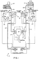
- the two-component mixing and dispensing system 10 comprises two hot-melt applicators 12 and 14, two metering pumps 16 and 18, and a dispenser 20. Additionally, there is associated with each metering pump 16 and 18 a back pressure control means 22, 24, respectively.
- the hot-melt applicators 12 and 14 are two different types of applicators because of the different volumes of material which each is required to melt and pump to the metering pumps 16 and 18 via the interconnecting conduits 26 and 28, respectively.
- the hot melt applicator 12 is operative to melt and supply under pressure from a pump contained internally of the applicator a first polymeric material which is utilized in less volume than the component supplied from the bulk hot-melt applicator 14.
- One hot-melt applicator 12 suitable for melting and pumping to the system the smaller volume polymeric component of this application is completely disclosed in U.S. Patent No. 3,964,645 issued June 22, 1976 and assigned to the assignee of this application.
- a bulk melter 14 suitable for melting and supplying under pressure the main or high volume polymeric component utilized in this application is completely disclosed in U.S. Patent No. 4,073,409 issued February 14, 1978.
- the metering pumps 16 and 18 may be gear-type, motor-driven pumps operative to supply molten polymeric material via the conduits 26 and 28, respectively, to the dispenser 20.
- the volume at which each component is supplied to the dispenser is controlled by the speed of the variable-speed motors 16a, 18a utilized to drive the gear 16b, 18b of the pumps 16 and 18, respectively.
- the metering pumps are coupled or linked electrically such that the ratio of the volume or mass dispensed from one metering pump is in proportion to the volume or mass dispensed from the other one.
- the gear pump 16 the molten polymeric material derived from the hot-melt applicator 12 is supplied to the dispenser 20 via a conduit 30 through an air-operated solenoid valve 32 of the dispenser 20.
- the main or high-volume polymeric material is supplied via a conduit 34 to another air-operated solenoid valve 36 of the dispenser 20.
- These valves 32 and 36 are individually operable to control the flow of the two different components into a mixing chamber 38 of the dispenser where the two different materials are for the first time combined.
- the two materials flow through a conventional static mixer 40 of the type which is operative to repeatedly divide and recombine the mixture in the course of passage through the mixer such that by the time the two components reach the discharge orifice 42 of the dispenser 20, the two components have been thoroughly mixed.
- the chemical reaction between the two polymeric materials which occurs upon combination of the two is occurring in the course of passage through the mixer and continues after the components are dispensed from the outlet 42 thereof.
- Each back pressure control means 22, 24 includes a bypass flow path 46, 48 around the gear pump 16, 18 with which it is associated.
- This bypass flow path comprises a flow conduit extending from the discharge side of the gear pump and its conduit 30, 34 to the input side of the gear pump and its input conduit 26, 28.
- the adjustable pressure regulator means may take the form of a simple adjustable needle valve forming an adjustable restrictor in the bypass flow path 46, 48 or it may take the form of an adjustable pressure regulator valve.
- the function of this adjustable pressure regulator means 54, 54' is to regulate and control the back pressure in the bypass flow path 46, 48 when the flow control valves 52, 52' are open.
- each bypass flow path 46, 48 includes an overload pressure regulator in the form of a pressure relief valve 56, 56' connected in parallel with the flow control valve 52, 52' and adjustable pressure control means 54, 54'.
- the function of the overload pressure relief valve 56, 56' is to bypass liquid from the discharge side of the metering pump to the inlet side in the event that the pressure on the discharge side of the metering pump exceeds a preset pressure substantially above the operating pressure at which the particular component is to be supplied from the applicator 12 or 14 to the dispenser 20.
- Air pressure is supplied alternatively to the air-pressure-operated solenoids 32, 36 of the dispenser 20 and the pneumatically operated flow control valves 52, 52' of the back pressure control means 22 and 24. That is, when air pressure is supplied to the solenoids 32, 34 of the dispenser so as to cause those valves to open and permit flow of liquid to the mixing chamber 38 of the dispenser, the flow control valves 52, 52' of the manifolds 22 and 24 are closed. Alternatively, when the flow control valves 52, 52' are open such that liquid can flow through the bypass flow paths, the solenoids 32, 36 are closed, and flow of liquid to the mixing chamber 38 is shut off.
- the first or smaller volume component polymeric material is supplied in solid form to the hot-melt applicator 12.
- this component is referred to as the smaller volume component but it could obviously be supplied at the same volume as the second component and still be within the practice of this invention.
- this material is melted and converted from the solid to the liquid state.
- This liquid smaller volume component, or component No. 1 is supplied via a pump contained in the applicator 12 under pressure to the metering pump 16.
- the metering pump is operative to supply the molten liquid component No. 1 at a desired flow rate to the discharge side of the metering pump.
- the output flow from the metering pump 16 is routed via the now open flow control valve 52 and pressure regulator means 54 in the bypass flow path 46, back to the input side of the gear pump 16.
- This bypass flow of component No. 1 will continue until the dispenser flow control valve 32 is opened.
- the high volume or main component, component No. 2 solid material is melted by the bulk hot-melt applicator 14 and is supplied under pressure from a pump contained internally of the bulk melter 14 to the metering pump 18.
- the pressure of the smaller volume component No. 1 at the input side of the dispenser 20 is in the steady state flow condition of the dispenser when the two components are being mixed and dispensed through the dispenser 20.
- the pressure regulator means 54, 54' are adjusted so as to maintain the pressure at the inlet to the dispenser at about the same pressure as was recorded by pressure transducer and/or pressure readout gauges 60, 62 on the input sides of the dispenser 20 in the steady state flow condition, i.e., when the flow control valves 32, 36 of the dispenser were open and the flow control valves 52, 52' were closed.
- the pressure regulator means 54, 54' may be either manually set and operated, or they may be automatically adjusted. If set manually, they will be adjusted so as to maintain a fixed pressure at the inlet side of the dispenser 20 (as read on pressure gauges or pressure transducers 60, 62) when the flow control valves 32, 36 of the dispenser are opened and the flow control valves 52, 52' of the back pressure control means 22, 24 are closed and vice versa.
- the adjustable pressure regulator means 54, 54' may be adjusted by utilizing a closed loop control circuit, including a computer or programmable controller as part of the electrical control 75, to manipulate the adjustment of the pressure regulator means 54, 54' so as to maintain the input pressure to the dispenser at about the same pressure after closing of the dispensing flow control valves 32, 36 as prevailed immediately prior to the closing of the flow control valves 32, 34.
- the steady state pressure is determined for each cycle and the valves 54, 54' adjusted accordingly. This can be accomplished by utilizing pressure transducers for the gauges 60, 62 to provide input signals via lines 66, 68 to the electrical control 75.
- the pressure settings of the pressure regulator means 54, 54' may then be adjusted by the electrical control 75 acting on the pressure control means 54, 54' by signals transmitted via leads 72, 74.
- the pressure reading at the pressure gauge or transducer 60 located at the inlet to the dispenser will be substantially the same pressure in both conditions of the dispenser, i.e., when the dispenser is operated so as to permit the two components to flow through the dispenser and when the flow control valves of the dispenser are closed and there is no material flowing through the dispenser.
- the pressure reading at the pressure transducer or gauge 62 located at the inlet to the dispenser will read substantially the same pressure in both conditions of the dispenser 20, i.e., when the dispenser is operated so as to permit the two components to flow through the dispenser and when the flow control valves of the dispenser are closed and there is no material flowing through the dispenser.
- FIG. 2 there is illustrated a flow vs. time chart which illustrates in solid lines the condition which obtains in the prior art when prior art dispensing systems are operated without the back pressure control means 22, 24 of this invention, and specifically without the bypass flow paths 46, 48, including the flow control valves 52, 52' and adjustable pressure regulator means 54, 54'.
- the flow control valves 32, 36 of the dispenser 20 initially opened at time equal to zero, the flow of component No. 2, immediately climbs to a flow rate 80 substantially above the desired flow rate 82, 82'. This is because the pressure on the input side of the dispenser 20 builds up, with the valves 32, 36 closed, and the metering pumps continuing to run, to a pressure substantially above the steady state flow rate pressure.
- the flow of the main component or high-volume component settles down to the desired flow rate 82.
- the second component No. 1 enters the mixing chamber 38 at a lesser pressure than component No. 2, the entry of that component is partially blocked by the excessive pressure of the other component No. 1. Therefore, the flow 84 of that second component No. 1 is retarded by the excessive pressure of component No. 2 until such time as component No. 2 settles down to its desired steady state flow rate. Only at that time does the component No. 1 flow rate move up to the desired flow rate 82.
- the ratio of component No. 2 to component No. 1 is substantially different from the desired ratio. Assuming component No.
- one pressure regular means 54 may be adjusted to maintain a pressure of, for example, 1.1 times that of the steady state pressure, while the other 54' may be set at, for example, 0.9 times the steady state pressure.
- the optimum settings may be determined empirically and may vary somewhat from one mixer to another and from one material to another.
- a multiplier may be set at 1.1. One hour later, it may be better set at 1.2. After two hours, it may be better set at 1.4. Therefore, a look-up table can be generated empirically for a given material and mixer type, and stored in memory within the control 75, which allows for different or varying multipliers to be applied to the reference or steady state pressure.
- the system can be mathematically modeled to produce a calculated look-up table or to calculate the next pressure setting of each cycle based on on-line measured values, such as input flow, temperature, pressure, or other parameters.
- mass ratio of two components of a two-component mixing and dispensing system in order to have the resulting mixed components have the desired properties.
- this may be a color or a drying time, or in the case of an adhesive, this may be a desired adhesive property and cure time.
- mass is a function of volume and density, and since density is a function of temperature, the volume of materials supplied to the dispenser by the metering pumps 16 and 18 must be varied in accordance with the temperature of the components if a fixed mass ratio between the two-component materials is to be maintained.
- variable speed motor 16a will vary the speed of the metering pump by that same 2.5 percent in order to maintain the same fixed total mass flow rate of materials dispensed from the dispenser 20.
- temperature measuring devices 64, 66 such as for example a thermocouple or a RTD, are provided for utilization in a closed loop control circuit. It is preferred that a temperature measuring device 64, 66 is located within each metering pump to provide an electrical signal indicative of the temperature of the liquid component material contained within the pump. The signals are furnished via leads 69, 71 to the electrical control 75 which may contain a computer or programmable controller.
- the electrical control 75 also includes drive controls 68 and 70, such as SCR drives, for controlling the speed of the motors 16a and 16b. In response to the temperature signals on levels 69, 71, the electrical control 75 provides signals to the respective drive control 68, 70 which, in turn, adjust the speed of the motors 16a, 16b accordingly.
- the computer is programmed to determine the volumetric and/or mass flow rates of a component as a function of the temperature received from one or both of the temperature measuring devices. If the computer determines that the change in temperature has affected the mass ratio or mass flow rate of a component, the computer will provide signals to adjust the speed of the motors 16a and 16b. For example, the total volumetric flow rate (Fv) of material dispensed from the dispenser is equal to the sum of the volumetric flow rate of the first component material (Fv1) plus the volumetric flow rate of the second component material (Fv2).
- the mass flow rate (Fm1, Fm2) of each component material is equal to the respective volumetric flow rate (Fv1, Fv2) times its specific gravity (SG1, SG2). Therefore, the volumetric flow rate of each component material can be determined from the following equations: where Rm is the mass ratio.
- the specific gravity of materials is temperature dependent. Therefore, for a given component material the computer can either calculate or use a look-up table to determine the specific gravity (SG1, SG2) at various temperatures sensed by the temperature sensing devices.
- the mass ratio (Rm) is the desired mass ratio of the components involved for the specific application. This term then is a constant for a given application.
- the total volumetric flow rate (Fv) is the desired volumetric flow rate for a specific application. This term then is also a constant for a given application.
- the variables of the volumetric flow rate (Fv1, Fv2) for each component are the specific gravities (SG1, SG2) which are temperature dependent. If the temperature of the first component increases, the specific gravity (SG1) will decrease requiring the volumetric flow rate of pump 16 to be increased in order to satisfy equation 1, where the mass ratio and the total volumetric flow rate are constant. After the new flow rate (Fv1) has been calculated, the computer will provide signals to the drive control 68 which increases the speed of the motor 16a and, in turn, the pump 16b.
- a change in the specific gravity of one component will require a change in the other components' volumetric flow rate because the specific gravity (SG1, SG2) of both components is found in both volumetric flow rate equations. Therefore, in the above example, if the specific gravity (SG1) of the first component decreases, this will result in a decrease in the volumetric flow rate (Fv2) of the second component.
- the computer will then provide signals to the drive control 70 which decreases the speed of the motor 18a and, in turn, the pump 18b which produces a flow rate equal to the newly calculated (Fv2).
- a variation of the specific gravity of one component does not require a corresponding change in the volumetric flow rate of the other component. Therefore, maintaining a constant total mass output flow rate and a constant mass ratio produces a simplified control because a change in the specific gravity of one component produces a change in speed of only the respective pump for that one component.
Landscapes
- Engineering & Computer Science (AREA)
- Mechanical Engineering (AREA)
- Chemical & Material Sciences (AREA)
- Chemical Kinetics & Catalysis (AREA)
- Physics & Mathematics (AREA)
- General Physics & Mathematics (AREA)
- Automation & Control Theory (AREA)
- Accessories For Mixers (AREA)
- Processing And Handling Of Plastics And Other Materials For Molding In General (AREA)
- Coating Apparatus (AREA)
- Application Of Or Painting With Fluid Materials (AREA)
- Measuring Volume Flow (AREA)
Applications Claiming Priority (2)
| Application Number | Priority Date | Filing Date | Title |
|---|---|---|---|
| US64006091A | 1991-01-11 | 1991-01-11 | |
| US640060 | 1991-01-11 |
Publications (3)
| Publication Number | Publication Date |
|---|---|
| EP0494453A2 true EP0494453A2 (fr) | 1992-07-15 |
| EP0494453A3 EP0494453A3 (en) | 1992-10-21 |
| EP0494453B1 EP0494453B1 (fr) | 1995-10-04 |
Family
ID=24566684
Family Applications (1)
| Application Number | Title | Priority Date | Filing Date |
|---|---|---|---|
| EP91122343A Expired - Lifetime EP0494453B1 (fr) | 1991-01-11 | 1991-12-28 | Méthode et appareil pour mesurer le débit d'un système de distribution à deux composants |
Country Status (9)
| Country | Link |
|---|---|
| US (1) | US5332125A (fr) |
| EP (1) | EP0494453B1 (fr) |
| JP (1) | JP3179543B2 (fr) |
| KR (1) | KR100195775B1 (fr) |
| AU (1) | AU644930B2 (fr) |
| CA (1) | CA2057948A1 (fr) |
| DE (1) | DE69113606T2 (fr) |
| ES (1) | ES2079548T3 (fr) |
| MX (1) | MX9200110A (fr) |
Cited By (11)
| Publication number | Priority date | Publication date | Assignee | Title |
|---|---|---|---|---|
| FR2694507A1 (fr) * | 1992-08-07 | 1994-02-11 | Graco Inc | Procédé de dosage d'un fluide ayant au moins deux constituants. |
| EP0599104A1 (fr) * | 1992-11-23 | 1994-06-01 | Nordson Corporation | Méthode et dispositif pour la compensation en changes de viscosité dans un système d'alimentation à deux composants |
| WO1994025238A1 (fr) * | 1993-05-05 | 1994-11-10 | E.I. Du Pont De Nemours And Company | Dispositif de precision servant a l'apport de liquides |
| WO1999051411A1 (fr) * | 1998-04-04 | 1999-10-14 | Reinhard Düspohl Maschinenbau Gmbh | Procede et dispositif pour produire des adhesifs reactifs a deux composants |
| EP0990198A2 (fr) * | 1996-11-20 | 2000-04-05 | Fluid Research Corporation | Procede et dispositif pour distribuer avec precision des liquides et des solides |
| EP1437210A1 (fr) * | 2003-01-07 | 2004-07-14 | Hennecke GmbH | Procédé pour la fabrication de pièces moulées en polyuréthane |
| WO2008150657A1 (fr) * | 2007-06-04 | 2008-12-11 | Illinois Tool Works Inc. | Système de distribution hybride d'un adhésif thermofusible ou autre matériau thermoplastique |
| CN100588469C (zh) * | 2006-07-31 | 2010-02-10 | 伊利诺斯器械工程公司 | 通过具有通用连接器的较短软管互相连接的远程计量台和喷头 |
| DE19504482B4 (de) * | 1995-02-10 | 2010-04-01 | Martinrea Industries, Inc., Manchester | Verfahren und Einrichtung zum klebenden Verbinden unter Verwendung nicht komprimierbarer Teilchen |
| EP2808144A1 (fr) * | 2013-05-31 | 2014-12-03 | Faurecia Automotive Composites | Dispositif et procédé de mélange d'au moins deux matériaux thermoplastiques présentant un ratio massique régulé |
| EP3511138A1 (fr) * | 2018-01-15 | 2019-07-17 | Afros S.P.A. | Tête de mélange à agitation mécanique pour résines de réactifs et ensemble de mélange relatif |
Families Citing this family (56)
| Publication number | Priority date | Publication date | Assignee | Title |
|---|---|---|---|---|
| US6696147B1 (en) * | 1992-04-16 | 2004-02-24 | Thyssenkrupp Budd Company | Beaded adhesive and flanged part made therefrom |
| US5470416A (en) | 1992-04-16 | 1995-11-28 | The Budd Company | Bonding method using mixture of adhesive and non-compressible beads |
| US5485941A (en) * | 1994-06-30 | 1996-01-23 | Basf Corporation | Recirculation system and method for automated dosing apparatus |
| US5938079A (en) * | 1995-01-27 | 1999-08-17 | Nordson Corporation | Dispensing head for two-component foam with shutoff |
| US5616625A (en) * | 1995-02-17 | 1997-04-01 | National Starch And Chemical Investment Holding Corporation | Reactive hot melt foam |
| US5862946A (en) * | 1996-07-12 | 1999-01-26 | Air Products And Chemicals, Inc. | Gas dissolution under pressure |
| JPH1099756A (ja) * | 1996-10-01 | 1998-04-21 | Fuji Mach Mfg Co Ltd | 接着剤ディスペンサ |
| US6010032A (en) * | 1997-06-19 | 2000-01-04 | Emes N.V. | Continuous dispensing system for liquids |
| US5992686A (en) * | 1998-02-27 | 1999-11-30 | Fluid Research Corporation | Method and apparatus for dispensing liquids and solids |
| US6039217A (en) * | 1998-04-07 | 2000-03-21 | Nordson Corporation | Apparatus and method for thermoplastic material handling |
| US6695589B1 (en) * | 1999-03-26 | 2004-02-24 | General Motors Corporation | Control for an electric motor driven pump |
| US7006896B1 (en) | 1999-10-13 | 2006-02-28 | Graco Minnesota Inc. | Sealant dispensing correction method |
| US6541063B1 (en) | 1999-11-04 | 2003-04-01 | Speedline Technologies, Inc. | Calibration of a dispensing system |
| DE60030773T2 (de) * | 1999-12-03 | 2007-11-08 | Graco Minnesota Inc., Minneapolis | Vorrichtung zum ausgeben mehrerer komponenten |
| US7905653B2 (en) * | 2001-07-31 | 2011-03-15 | Mega Fluid Systems, Inc. | Method and apparatus for blending process materials |
| EP1749565A1 (fr) * | 2000-07-31 | 2007-02-07 | Kinetics Chempure Systems, Inc. | Procédé et appareil pour mélanger des matériaux de traitement |
| EP1305107B1 (fr) * | 2000-07-31 | 2006-09-20 | Kinetics Chempure Systems, Inc. | Procede et dispositif permettant de melanger des matieres de traitement |
| US6704617B2 (en) | 2002-04-11 | 2004-03-09 | Flexible Products Company | Automated system for control and diagnostics for dispensing systems |
| DE20205819U1 (de) | 2002-04-12 | 2003-08-21 | Kinetics Germany Gmbh | Vorrichtung zur Bereitstellung von hochreinen Prozesschemikalien |
| US7344298B2 (en) * | 2002-07-19 | 2008-03-18 | Celerity, Inc. | Method and apparatus for blending process materials |
| WO2004042484A2 (fr) * | 2002-11-04 | 2004-05-21 | Graco Minnesota Inc. | Doseur pour produits durcissant rapidement |
| US20040148763A1 (en) * | 2002-12-11 | 2004-08-05 | Peacock David S. | Dispensing system and method |
| ES2214134B1 (es) * | 2003-02-20 | 2005-11-01 | Asm-Dimatec Ingenieria, S.A. | Sistema mezclador-dosificador bicomponente. |
| US6929153B1 (en) * | 2003-03-19 | 2005-08-16 | Horst Gerich | Fluid dispensing apparatus with check-valve operated mixing ability |
| EP1635937A1 (fr) * | 2003-06-02 | 2006-03-22 | Dow Corning Corporation | Appareil de preparation d'elastomeres de silicone liquide de composition et de tonalite uniformes |
| WO2004111551A2 (fr) * | 2003-06-07 | 2004-12-23 | Rsm Technologies, Inc. | Systeme de pompe a chauffage permettant l'acheminement de constituants multiples selon un rapport predetermine vers un dispositif d'application par pulverisation |
| US20050252547A1 (en) * | 2004-05-11 | 2005-11-17 | Applied Materials, Inc. | Methods and apparatus for liquid chemical delivery |
| US7350672B1 (en) | 2004-09-30 | 2008-04-01 | Horst Gerich | Fluid dispensing apparatus |
| KR100692234B1 (ko) | 2005-12-09 | 2007-03-12 | (주)삼성금속 | 단열재 주입장치 |
| JP4984655B2 (ja) * | 2006-05-31 | 2012-07-25 | 横浜ゴム株式会社 | 二液混合吐出装置 |
| JP5396725B2 (ja) | 2008-03-19 | 2014-01-22 | 富士通株式会社 | 情報処理装置、情報処理方法および履歴情報蓄積部制御プログラム |
| US8740013B2 (en) * | 2008-04-01 | 2014-06-03 | Pfp Control Technologies, Llc | Variable flow air flow controller |
| JP5292037B2 (ja) * | 2008-09-25 | 2013-09-18 | 理想科学工業株式会社 | インクジェット記録装置 |
| EP2198949A1 (fr) * | 2008-12-18 | 2010-06-23 | Sika Technology AG | Outil de distribution pour substances à plusieurs composants |
| JP5253258B2 (ja) * | 2009-03-25 | 2013-07-31 | 富士フイルム株式会社 | 液体吐出装置 |
| UA104306C2 (uk) * | 2009-03-26 | 2014-01-27 | Ґрако Міннесота Інк. | Спосіб розподілення декількох матеріальних компонентів |
| US20130025699A1 (en) * | 2009-12-29 | 2013-01-31 | Kimco Pte Inc. | Resin distributor, reservoir bag to be used therewith, vehicle provided with such a system, kit for assembling the same, and methods of assembling and of operating associated thereto |
| US20160067735A1 (en) | 2009-12-29 | 2016-03-10 | Kimco Pte Inc. | Resin distributor, reservoir bag to be used therewith, vehicle provided with such a system, kit for assembling the same, and methods of assembling and of operating associated thereto |
| WO2011123503A1 (fr) | 2010-04-01 | 2011-10-06 | B & H Manufacturing Company, Inc. | Système d'application d'extrusion |
| MX343727B (es) * | 2010-06-24 | 2016-11-18 | Graco Minnesota Inc | Montaje de valvula de circulacion de fluido para dispensador de fluido. |
| EP2796536B1 (fr) * | 2011-12-22 | 2017-08-09 | Panasonic Healthcare Holdings Co., Ltd. | Dispositif de distribution |
| US9242267B2 (en) | 2013-01-31 | 2016-01-26 | Owens Corning Intellectual Capital, Llc | Method and apparatus for mixing and applying material |
| US10136674B2 (en) | 2014-02-28 | 2018-11-27 | Beyond Twenty Ltd. | Electronic vaporiser system |
| US10219538B2 (en) | 2014-02-28 | 2019-03-05 | Beyond Twenty Ltd. | Electronic vaporiser system |
| US10099916B2 (en) | 2014-02-28 | 2018-10-16 | Beyond Twenty Ltd. | Electronic vaporiser system |
| US11085550B2 (en) | 2014-02-28 | 2021-08-10 | Ayr Ltd. | Electronic vaporiser system |
| GB201413037D0 (en) | 2014-02-28 | 2014-09-03 | Beyond Twenty Ltd | Beyond 10 |
| US10091839B2 (en) | 2014-02-28 | 2018-10-02 | Beyond Twenty Ltd. | Electronic vaporiser system |
| US10588176B2 (en) | 2014-02-28 | 2020-03-10 | Ayr Ltd. | Electronic vaporiser system |
| DE102015109770A1 (de) * | 2015-06-18 | 2016-12-22 | Kraussmaffei Technologies Gmbh | Schmelzvorrichtung zum Schmelzen von schmelzbarem Kunststoffmaterial |
| AU2016313955B2 (en) | 2015-09-01 | 2021-01-28 | Ayr Ltd | Electronic vaporiser system |
| US10035168B1 (en) * | 2015-10-21 | 2018-07-31 | Horst Gerich | Low pressure two component fluid metering, mixing and dispensing system |
| DE102015121535B4 (de) * | 2015-12-10 | 2018-12-06 | Marco Systemanalyse Und Entwicklung Gmbh | Vorrichtung und Verfahren zum Mischen |
| EP3386618A4 (fr) * | 2015-12-11 | 2019-11-27 | Cobbler Technologies | Techniques de fabrication avancées ultravariables |
| US10639669B2 (en) * | 2018-03-16 | 2020-05-05 | Nordson Corporation | Electrically operated pressure control valve |
| US11986780B2 (en) | 2019-03-15 | 2024-05-21 | Nordson Corporation | Hot melt adhesive foam dispensing system |
Citations (5)
| Publication number | Priority date | Publication date | Assignee | Title |
|---|---|---|---|---|
| EP0025871A1 (fr) * | 1979-09-07 | 1981-04-01 | Bayer Ag | Procédé pour produire un mélange de réaction à partir de composants liquides formant une mousse plastique ou une matière plastique dense |
| GB2163360A (en) * | 1984-08-24 | 1986-02-26 | Spuehl Ag | Mixer heads for plastics material components |
| EP0374300A1 (fr) * | 1987-11-10 | 1990-06-27 | Krauss-Maffei Aktiengesellschaft | Dispositif de mélange à jets opposés avec ajustement des buses à pression contrôlée |
| WO1991010551A1 (fr) * | 1990-01-18 | 1991-07-25 | Henderson's Industries Pty. Ltd. | Procedes et appareil de moulage ameliores |
| EP0473424A2 (fr) * | 1990-08-30 | 1992-03-04 | Nordson Corporation | Formation et distribution de peinture mono et polyphasique contenant un diluant fluide |
Family Cites Families (16)
| Publication number | Priority date | Publication date | Assignee | Title |
|---|---|---|---|---|
| US3786990A (en) * | 1972-07-17 | 1974-01-22 | Graco Inc | Plural component gun |
| US3964645A (en) * | 1975-02-12 | 1976-06-22 | Nordson Corporation | Apparatus for melting and dispensing thermoplastic material |
| US4019653A (en) * | 1975-08-22 | 1977-04-26 | Graco Inc. | Automatic proportioning paint spray system |
| US4073409A (en) * | 1977-01-12 | 1978-02-14 | Fluid Kinetics, Inc. | Hot melt dispenser with removeable pump in follower |
| US4200207A (en) * | 1978-02-01 | 1980-04-29 | Nordson Corporation | Hot melt adhesive foam pump system |
| US4341327A (en) * | 1980-02-28 | 1982-07-27 | Vernon Zeitz | Digital proportional metering pumping system |
| GB2123360A (en) * | 1982-07-13 | 1984-02-01 | Dunlop Ltd | Tyre bead reinforcements |
| US4850514A (en) * | 1982-12-16 | 1989-07-25 | Nordson Corporation | Constant pressure intermittent fluid dispenser |
| US4493286A (en) * | 1983-07-25 | 1985-01-15 | Koppers Company, Inc. | Method and apparatus for applying a multi-component adhesive |
| US4548652A (en) * | 1983-09-06 | 1985-10-22 | Graco Inc. | Method of purging a plural component mixing and dispensing system |
| US4522504A (en) * | 1983-12-08 | 1985-06-11 | Pyles Division | Linear in-line mixing system |
| JPS61263665A (ja) * | 1985-05-17 | 1986-11-21 | Toyota Motor Corp | 2液混合型塗装装置 |
| IT1204812B (it) * | 1986-02-19 | 1989-03-10 | Siv Soc Italiana Vetro | Procedimento per la fabbricazione di una vetrata di sicurezza per autoveicoli ed edifici,e prodotto cosi' ottenuto |
| US5005765A (en) * | 1988-01-25 | 1991-04-09 | Specified Equipment Systems Company, Inc. | Method and apparatus for applying multicomponent materials |
| FR2626501B1 (fr) * | 1988-01-29 | 1992-01-03 | Graco France Sa | Procede d'alimentation de moyens d'extrusion ou de pulverisation de produit pateux, dispositif d'alimentation et installation comportant le dispositif |
| US5162121A (en) * | 1988-01-30 | 1992-11-10 | Toyo Seikan Kaisha, Ltd. | Apparatus for extruding multiple synthetic resins |
-
1991
- 1991-12-18 CA CA002057948A patent/CA2057948A1/fr not_active Abandoned
- 1991-12-28 DE DE69113606T patent/DE69113606T2/de not_active Expired - Fee Related
- 1991-12-28 EP EP91122343A patent/EP0494453B1/fr not_active Expired - Lifetime
- 1991-12-28 ES ES91122343T patent/ES2079548T3/es not_active Expired - Lifetime
-
1992
- 1992-01-07 AU AU10100/92A patent/AU644930B2/en not_active Ceased
- 1992-01-10 KR KR1019920000248A patent/KR100195775B1/ko not_active IP Right Cessation
- 1992-01-10 MX MX9200110A patent/MX9200110A/es unknown
- 1992-01-10 JP JP00303692A patent/JP3179543B2/ja not_active Expired - Fee Related
- 1992-09-10 US US07/943,105 patent/US5332125A/en not_active Expired - Fee Related
Patent Citations (5)
| Publication number | Priority date | Publication date | Assignee | Title |
|---|---|---|---|---|
| EP0025871A1 (fr) * | 1979-09-07 | 1981-04-01 | Bayer Ag | Procédé pour produire un mélange de réaction à partir de composants liquides formant une mousse plastique ou une matière plastique dense |
| GB2163360A (en) * | 1984-08-24 | 1986-02-26 | Spuehl Ag | Mixer heads for plastics material components |
| EP0374300A1 (fr) * | 1987-11-10 | 1990-06-27 | Krauss-Maffei Aktiengesellschaft | Dispositif de mélange à jets opposés avec ajustement des buses à pression contrôlée |
| WO1991010551A1 (fr) * | 1990-01-18 | 1991-07-25 | Henderson's Industries Pty. Ltd. | Procedes et appareil de moulage ameliores |
| EP0473424A2 (fr) * | 1990-08-30 | 1992-03-04 | Nordson Corporation | Formation et distribution de peinture mono et polyphasique contenant un diluant fluide |
Non-Patent Citations (1)
| Title |
|---|
| PLASTICS ENGINEERING vol. 39, no. 11, November 1983, MANCHESTER,NEW HAMPSHIRE,USA pages 33 - 35; PEETERS,JR.: 'exacting rim process controls help yield higher-quality plastics parts' * |
Cited By (18)
| Publication number | Priority date | Publication date | Assignee | Title |
|---|---|---|---|---|
| FR2694507A1 (fr) * | 1992-08-07 | 1994-02-11 | Graco Inc | Procédé de dosage d'un fluide ayant au moins deux constituants. |
| EP0599104A1 (fr) * | 1992-11-23 | 1994-06-01 | Nordson Corporation | Méthode et dispositif pour la compensation en changes de viscosité dans un système d'alimentation à deux composants |
| AU668227B2 (en) * | 1992-11-23 | 1996-04-26 | Nordson Corporation | Method and apparatus for compensating for changes in viscosity in a two-component dispensing system |
| WO1994025238A1 (fr) * | 1993-05-05 | 1994-11-10 | E.I. Du Pont De Nemours And Company | Dispositif de precision servant a l'apport de liquides |
| DE19504482B4 (de) * | 1995-02-10 | 2010-04-01 | Martinrea Industries, Inc., Manchester | Verfahren und Einrichtung zum klebenden Verbinden unter Verwendung nicht komprimierbarer Teilchen |
| EP0990198A2 (fr) * | 1996-11-20 | 2000-04-05 | Fluid Research Corporation | Procede et dispositif pour distribuer avec precision des liquides et des solides |
| EP0990198A4 (fr) * | 1996-11-20 | 2001-07-18 | Fluid Res Corp | Procede et dispositif pour distribuer avec precision des liquides et des solides |
| WO1999051411A1 (fr) * | 1998-04-04 | 1999-10-14 | Reinhard Düspohl Maschinenbau Gmbh | Procede et dispositif pour produire des adhesifs reactifs a deux composants |
| US7404916B2 (en) * | 2003-01-07 | 2008-07-29 | Hennecke Gmbh | Process for producing polyurethane moldings |
| EP1437210A1 (fr) * | 2003-01-07 | 2004-07-14 | Hennecke GmbH | Procédé pour la fabrication de pièces moulées en polyuréthane |
| CN100588469C (zh) * | 2006-07-31 | 2010-02-10 | 伊利诺斯器械工程公司 | 通过具有通用连接器的较短软管互相连接的远程计量台和喷头 |
| WO2008150657A1 (fr) * | 2007-06-04 | 2008-12-11 | Illinois Tool Works Inc. | Système de distribution hybride d'un adhésif thermofusible ou autre matériau thermoplastique |
| CN101679812A (zh) * | 2007-06-04 | 2010-03-24 | 伊利诺斯工具制品有限公司 | 混合型热熔性粘合剂或其它热塑性材料分配系统 |
| US7908997B2 (en) | 2007-06-04 | 2011-03-22 | Illinois Tool Works Inc. | Hybrid hot melt adhesive or other thermoplastic material dispensing system |
| CN101679812B (zh) * | 2007-06-04 | 2014-10-15 | 伊利诺斯工具制品有限公司 | 混合型热熔性粘合剂或其它热塑性材料分配系统 |
| EP2808144A1 (fr) * | 2013-05-31 | 2014-12-03 | Faurecia Automotive Composites | Dispositif et procédé de mélange d'au moins deux matériaux thermoplastiques présentant un ratio massique régulé |
| FR3006229A1 (fr) * | 2013-05-31 | 2014-12-05 | Faurecia Automotive Composites | Dispositif et procede de melange d'au moins deux materiaux thermoplastiques presentant un ratio massique regule |
| EP3511138A1 (fr) * | 2018-01-15 | 2019-07-17 | Afros S.P.A. | Tête de mélange à agitation mécanique pour résines de réactifs et ensemble de mélange relatif |
Also Published As
| Publication number | Publication date |
|---|---|
| DE69113606T2 (de) | 1996-03-07 |
| JPH0688741A (ja) | 1994-03-29 |
| CA2057948A1 (fr) | 1992-07-12 |
| US5332125A (en) | 1994-07-26 |
| JP3179543B2 (ja) | 2001-06-25 |
| ES2079548T3 (es) | 1996-01-16 |
| EP0494453A3 (en) | 1992-10-21 |
| AU1010092A (en) | 1992-07-16 |
| AU644930B2 (en) | 1993-12-23 |
| DE69113606D1 (de) | 1995-11-09 |
| EP0494453B1 (fr) | 1995-10-04 |
| KR920014511A (ko) | 1992-08-25 |
| MX9200110A (es) | 1992-07-01 |
| KR100195775B1 (ko) | 1999-06-15 |
Similar Documents
| Publication | Publication Date | Title |
|---|---|---|
| US5332125A (en) | Method & apparatus for metering flow of a two-component dispensing system | |
| EP0599104B1 (fr) | Méthode et dispositif pour la compensation en changes de viscosité dans un système d'alimentation à deux composants | |
| US6220747B1 (en) | Proportional pump system for viscous fluids | |
| US7597931B2 (en) | Device and method for producing a foam material | |
| EP2988879B1 (fr) | Systeme et procede de repartition de constituants multiples | |
| JP3133320B2 (ja) | 発泡材料のガス含量を制御する方法および装置 | |
| WO1999043606A1 (fr) | Procede et appareil de distribution de liquides et de solides | |
| SE508434C2 (sv) | Metod och system vid dosering | |
| US5823388A (en) | Liquid dispenser having flow rate compensation | |
| US6942736B2 (en) | Automatically controlled flow applicator | |
| US8512805B2 (en) | Method for dispensing foam onto substrates of large width | |
| US3107034A (en) | Liquid supply and mixing system | |
| JP2002528251A (ja) | 相異なる成分の配量及び混合方法並びに装置 | |
| CA1267574A (fr) | Methode et dispositif de controle de la teneur en gaz d'une mousse adhesive thermoplastique debitee en fusion | |
| JP7335074B2 (ja) | 流動性物質を断続的に塗布する装置およびこのような物質を塗布する方法 | |
| US5733379A (en) | Method for cleaning a mixer | |
| US20030041903A1 (en) | Method of dispensing adhesive and sealant | |
| JPH0233898Y2 (fr) | ||
| RU2756468C1 (ru) | Система для смешивания материалов, имеющая буферную емкость | |
| JPH08266878A (ja) | 液体連続混合装置 | |
| JP2981389B2 (ja) | 擬塑性流体の定量吐出制御方法 | |
| JPH06134270A (ja) | 液状物質の混合装置 |
Legal Events
| Date | Code | Title | Description |
|---|---|---|---|
| PUAI | Public reference made under article 153(3) epc to a published international application that has entered the european phase |
Free format text: ORIGINAL CODE: 0009012 |
|
| AK | Designated contracting states |
Kind code of ref document: A2 Designated state(s): BE CH DE ES FR GB IT LI SE |
|
| PUAL | Search report despatched |
Free format text: ORIGINAL CODE: 0009013 |
|
| AK | Designated contracting states |
Kind code of ref document: A3 Designated state(s): BE CH DE ES FR GB IT LI SE |
|
| 17P | Request for examination filed |
Effective date: 19921105 |
|
| 17Q | First examination report despatched |
Effective date: 19940808 |
|
| GRAA | (expected) grant |
Free format text: ORIGINAL CODE: 0009210 |
|
| AK | Designated contracting states |
Kind code of ref document: B1 Designated state(s): BE CH DE ES FR GB IT LI SE |
|
| ET | Fr: translation filed | ||
| REF | Corresponds to: |
Ref document number: 69113606 Country of ref document: DE Date of ref document: 19951109 |
|
| ITF | It: translation for a ep patent filed |
Owner name: MODIANO & ASSOCIATI S.R.L. |
|
| REG | Reference to a national code |
Ref country code: ES Ref legal event code: FG2A Ref document number: 2079548 Country of ref document: ES Kind code of ref document: T3 |
|
| PLBE | No opposition filed within time limit |
Free format text: ORIGINAL CODE: 0009261 |
|
| STAA | Information on the status of an ep patent application or granted ep patent |
Free format text: STATUS: NO OPPOSITION FILED WITHIN TIME LIMIT |
|
| 26N | No opposition filed | ||
| PGFP | Annual fee paid to national office [announced via postgrant information from national office to epo] |
Ref country code: SE Payment date: 20011128 Year of fee payment: 11 |
|
| PGFP | Annual fee paid to national office [announced via postgrant information from national office to epo] |
Ref country code: CH Payment date: 20011129 Year of fee payment: 11 |
|
| PGFP | Annual fee paid to national office [announced via postgrant information from national office to epo] |
Ref country code: GB Payment date: 20011130 Year of fee payment: 11 Ref country code: FR Payment date: 20011130 Year of fee payment: 11 |
|
| PGFP | Annual fee paid to national office [announced via postgrant information from national office to epo] |
Ref country code: DE Payment date: 20011205 Year of fee payment: 11 |
|
| PGFP | Annual fee paid to national office [announced via postgrant information from national office to epo] |
Ref country code: ES Payment date: 20011213 Year of fee payment: 11 |
|
| PGFP | Annual fee paid to national office [announced via postgrant information from national office to epo] |
Ref country code: BE Payment date: 20011217 Year of fee payment: 11 |
|
| REG | Reference to a national code |
Ref country code: GB Ref legal event code: IF02 |
|
| PG25 | Lapsed in a contracting state [announced via postgrant information from national office to epo] |
Ref country code: GB Free format text: LAPSE BECAUSE OF NON-PAYMENT OF DUE FEES Effective date: 20021228 |
|
| PG25 | Lapsed in a contracting state [announced via postgrant information from national office to epo] |
Ref country code: SE Free format text: LAPSE BECAUSE OF NON-PAYMENT OF DUE FEES Effective date: 20021229 |
|
| PG25 | Lapsed in a contracting state [announced via postgrant information from national office to epo] |
Ref country code: ES Free format text: LAPSE BECAUSE OF NON-PAYMENT OF DUE FEES Effective date: 20021230 |
|
| PG25 | Lapsed in a contracting state [announced via postgrant information from national office to epo] |
Ref country code: LI Free format text: LAPSE BECAUSE OF NON-PAYMENT OF DUE FEES Effective date: 20021231 Ref country code: CH Free format text: LAPSE BECAUSE OF NON-PAYMENT OF DUE FEES Effective date: 20021231 Ref country code: BE Free format text: LAPSE BECAUSE OF NON-PAYMENT OF DUE FEES Effective date: 20021231 |
|
| BERE | Be: lapsed |
Owner name: *NORDSON CORP. Effective date: 20021231 |
|
| PG25 | Lapsed in a contracting state [announced via postgrant information from national office to epo] |
Ref country code: DE Free format text: LAPSE BECAUSE OF NON-PAYMENT OF DUE FEES Effective date: 20030701 |
|
| EUG | Se: european patent has lapsed | ||
| REG | Reference to a national code |
Ref country code: CH Ref legal event code: PL |
|
| GBPC | Gb: european patent ceased through non-payment of renewal fee |
Effective date: 20021228 |
|
| PG25 | Lapsed in a contracting state [announced via postgrant information from national office to epo] |
Ref country code: FR Free format text: LAPSE BECAUSE OF NON-PAYMENT OF DUE FEES Effective date: 20030901 |
|
| REG | Reference to a national code |
Ref country code: FR Ref legal event code: ST |
|
| REG | Reference to a national code |
Ref country code: ES Ref legal event code: FD2A Effective date: 20021230 |
|
| PG25 | Lapsed in a contracting state [announced via postgrant information from national office to epo] |
Ref country code: IT Free format text: LAPSE BECAUSE OF NON-PAYMENT OF DUE FEES;WARNING: LAPSES OF ITALIAN PATENTS WITH EFFECTIVE DATE BEFORE 2007 MAY HAVE OCCURRED AT ANY TIME BEFORE 2007. THE CORRECT EFFECTIVE DATE MAY BE DIFFERENT FROM THE ONE RECORDED. Effective date: 20051228 |