EP0490709A2 - System zur Kraftstoffsverbrauchsmessung - Google Patents
System zur Kraftstoffsverbrauchsmessung Download PDFInfo
- Publication number
- EP0490709A2 EP0490709A2 EP91311657A EP91311657A EP0490709A2 EP 0490709 A2 EP0490709 A2 EP 0490709A2 EP 91311657 A EP91311657 A EP 91311657A EP 91311657 A EP91311657 A EP 91311657A EP 0490709 A2 EP0490709 A2 EP 0490709A2
- Authority
- EP
- European Patent Office
- Prior art keywords
- fuel
- output
- flow
- measuring
- return
- Prior art date
- Legal status (The legal status is an assumption and is not a legal conclusion. Google has not performed a legal analysis and makes no representation as to the accuracy of the status listed.)
- Withdrawn
Links
Images

Classifications
-
- G—PHYSICS
- G01—MEASURING; TESTING
- G01F—MEASURING VOLUME, VOLUME FLOW, MASS FLOW OR LIQUID LEVEL; METERING BY VOLUME
- G01F15/00—Details of, or accessories for, apparatus of groups G01F1/00 - G01F13/00 insofar as such details or appliances are not adapted to particular types of such apparatus
- G01F15/02—Compensating or correcting for variations in pressure, density or temperature
- G01F15/022—Compensating or correcting for variations in pressure, density or temperature using electrical means
- G01F15/024—Compensating or correcting for variations in pressure, density or temperature using electrical means involving digital counting
-
- G—PHYSICS
- G01—MEASURING; TESTING
- G01F—MEASURING VOLUME, VOLUME FLOW, MASS FLOW OR LIQUID LEVEL; METERING BY VOLUME
- G01F9/00—Measuring volume flow relative to another variable, e.g. of liquid fuel for an engine
- G01F9/001—Measuring volume flow relative to another variable, e.g. of liquid fuel for an engine with electric, electro-mechanic or electronic means
Definitions
- This invention relates to new and useful improvements in fuel consumption measurement systems for engines and combustion systems which recirculate unburned fuel.
- the primary objective of this invention relates to a novel method of accurately monitoring and producing a signal related to fuel consumption for engines and combustion systems which recirculate unburned fuel. It features a bi-directional, volumetric fuel measurement system incorporating two magnetically actuated, positive displacement flow meters for the fuel consumption measurement.
- a precision pulse output generating mechanism is coupled with the fuel measurement system described above through a micro-processor type computer.
- the programmed micro-processor computer is designed to produce a designated frequency of the net fuel consumption measurement of two temperature compensated flow meters.
- the entire measurement mechanism is compactly situated in miniature form and is designed for (OEM) original equipment manufacturers, to interface into their display and/or recording equipment.
- OEM original equipment manufacturers
- Many original equipment manufacturers are involved with monitoring, displaying and/or recording a considerable number of engine or combustion device parameters, such as RPM, various pressures and temperatures.
- One parameter OEM's would like to monitor is fuel consumption, if an accurate and reliable fuel measurement instrument was available that was relatively inexpensive, simple to install on the engine or combustion device, and simple to interface into their host equipment.
- the pulse output frequency produced is user selectable, whereby it is possible to select the most desirable rate of flow frequency. For example: one pulse per gallon or liter of consumption; ten pulses per gallon or liter of consumption; 100 pulses per gallon or liter of consumption; 1000 pulses per gallon or liter of consumption; or 10,000 pulses per gallon or liter of consumption.
- a selectable pulse output of frequency, per unit of fuel is extremely desirable from a simplicity of manufacturing standpoint and for each individual (OEM) application to offer the ultimate accuracy resolution for each individual user requirement.
- a second objective of the invention features a miniaturized (OEM) fuel measurement instrument with a simultaneous combination of outputs. Namely, totalized consumption (Gallons or Liters) in one electrical conductor of a multi-conductor wiring harness, rate of consumption (Gallons or Liters per hour) in a second conductor and RPM in a third conductor, all in selectable pulse outputs and/or ASCI formats.
- OEM may require a fuel measurement instrument with a rate of flow frequency output in 10,000 pulses per liter increments, the totalizer output in single liter increments and a third output of RPM measurement.
- many OEM's require only the rate of flow output, as their host device is capable of integrating the fuel rate measurement into both rate of flow and totalized fuel flow measurements.
- a third objective of the invention involves the smoothness of the flow rate output frequency.
- a novel rate averaging mechanism is designed into the micro-processor software whereby the flow rate output frequency (tachometer output) tracks the engine RPM. This is counter to the flow rate output produced by conventional positive displacement flow meters utilized in a dual flow meter (rate of flow instrument.)
- a forth objective of the present invention features a precision fuel consumption measurement instrument, for combustion systems which return unburned fuel, which is miniature and portable, simple to install and operate, and which is relatively inexpensive to manufacture compared to prior precision devices.
- the entire fuel consumption measurement system is contained within the two fuel meters themselves.
- a fifth objective of the present invention features a user programmable multiplying output of net consumption relating to one, two or more engines being monitored.
- a second feature of this objective features a user programmable output of average generator flow rate wherin the generator fuel consumption is additive to the engine fuel consumption.
- a sixth objective of the present invention features an electronic digital readout display, indicating the compensated flow rate and / or totalized flow, as an integral part of the instrument.
- the entire, temperature compensated measurement system together with electronic digital readout display is physically contained within the two fuel meters themselves.
- the electronic instrumentation, located in the supply meter, is cooled via conduction by fuel being supplied to the engine.
- a final objective of the present invention features frequency outputs which are distinctly separate and individual in order to offer the OEM user an opportunity to analyze the individual flow rates for diagnostic purposes. (The OEM user then subtracts the two flow rates in his host equipment to obtain net fuel consumption.)
- the supply fuel flow rate frequency is output in one electrical conductor while the return flow rate frequency is output in a second electrical conductor.
- the supply fuel flow rate frequency is output in one wave length format while the return fuel flow rate frequency is output with a second wave length format.
- Fig. 1 is a diagrammatic view of the primary fuel measurement system of the invention and which particularly relates to an engine or combustion system which recirculates unburned fuel back to the fuel supply tank.
- Fig. 2 is a fragnentary diagramatic sectional view of the fuel supply and return meters and the RPM sensor assembly used therewith.
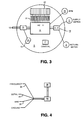
- Fig. 3 is a diagrammatic view of the fuel measurement systems primary printed circuit board together with the principal components located thereon.
- Fig. 4 is a plan view of an optical couplar assembly together with the output conduit and signal connectors.
- Fig. 5 is a frontal view of the supply meter together with an electronic readout display with rate and / or totalizing capability, mechanically and electronically attached and interfaced to the metering device and electronic instrumentation.
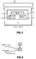
- Fig. 6 is a diagramatic view of an optical couplar assembly together with the electrical wiring necessary for individual and separate frequency outputs of supply and return fuel frequency.
- an engine or combustion device of the type which recirculates unburned fuel back to the fuel supply tank, incorporates a fuel meter measuring fuel supplied to the combustion device and a fuel meter measuring fuel returning to the fuel supply tank.
- the supply meter is designated by the numeral 1 and the return meter by the numeral 2.
- the fuel supply tank supplying fuel to the combustion system is designated by the numeral 3 and the combustion device by the numeral 4.
- piston 6 of fuel meter 1 is driven rotationally by the force of fuel flowing to the combustion device 4, by a conventional fuel pump.
- Magnet 7, of fuel meter 1 is mechanically connected to piston 6.
- Pickup sensor 8 is electrically connected to the measurement system computer circuit board 5 which is located in a separate compartment, enclosed by cover cap 10, of the fuel supply meter, fluidically sealed from the piston and magnet assembly.
- Temperature sensor 9 is capable of sensing fuel temperature of meter 1, and and is also electrically connected to the computer circuit board 5.
- the fuel flow rate signal and fuel temperature measurement of fuel flowing from the combustion device back to the fuel supply through return fuel meter 2 is electrically connected to the computer circuit board 5 via the electrical conduit and connector 14 which separates the the two meters.
- the fuel sensor 8a and temperature sensor 9a of return meter 2 are also fluidically sealed from the measurement chamber and enclosed by return meter cover cap 11. External power is supplied to the computer circuit board 5, located in the supply meter 1, through electrical conduit 13.
- a fuel flow signal, related to net fuel consumption, has the capability of being transmitted from the supply meter 1 through an opto-coupled device, later to be described, through conduit 12.
- a signal measuring the RPM of the engine or combustion device is obtained from the RPM sensor pickup assembly 15 which is connected to return meter 2 thru electrical conduit and connector 14a.
- a high powered fuel measurement system computer housed and entirely contained within the fuel measuring devices themselves, is designed and programmed to interface with the supply and return fuel meters described in Fig 1 and and Fig 2.
- the computer circuit board 5 is minaturized and designed to be located in a separate compartment of the fuel supply meter 1, isolated from the fluidic measurement portion of the meter.
- Computer circuit board 5 incorporates a micro-processor computer chip, of Motorola Corporation's Model HC 11 design family, which is the principle electronic component of the invention and is designated by the numeral 16. Power is supplied to circuit board 5, from an external source through electrical conduit 13, to the power regulation circuity 20 located on circuit board 5, then to the micro-processor chip 16 and supporting hardware.
- Forming a part of the invention is an electrical connection from the fuel flow sensor 8 of a meter 1 to the processor chip 16 furnishing the computer micro-processor with data related to flow rate of fuel supplied to the engine or combustion device. Additionally, an electrical connection from sensor 8a of return meter 2 to the processor chip 16 furnishes the computer chip 16 flow rate data related to fuel returning from the combustion device back to the fuel supply tank. Fuel temperature information from the temperature sensor 9 of the fuel supply meter 1 is transmitted to an analog to digital converter 19, of standard electronic manufacture, located on circuit board 5, for conversion of the data from an analog format to a digital format.
- Fuel temperature information from the temperature sensor 9a of the fuel return meter 2 is transmitted thru a second channel of the analog to digital convertor 19 located on circuit board 5, for conversion of the data from an analog format to digital format.
- Digital fuel temperature data relating to both supply meter 1 and return meter 2 is then transmittted from the analog to digital convertor 19 to separate channels of the micro-processor chip 16 for temperature compensation of fuel flowing thru fuel supply meter 1 and fuel return meter 2.
- a precision eight mega-hertz crystal for example manufactured by the Saronix Corporation, designated by the numeral 17, is interfaced to the processor computing chip 16 which allows the processor access to a substantial quantity of precision logic pulses for mathematical computations related to fuel flow rate.
- a twelve position rocker type dip switch 22, of standard electronic manufacture which is interfaced to the micro-processor computing chip 16 through a series of resistors 21, allowing for an independent combination of switch selections.
- Micro-processor chip 16 with data received from crystal 17 and fuel flow sensors 8 and 9 of meter 1 and flow sensors 8a and 9a of meter 2, has been designed and programmed to determine and produce a digital data stream output of the net temperature compensated measurement of both fuel flow meters. More simply stated, the data stream output produced is a digital resultant of the temperature compensated measurement of return meter 2 subtracted from the temperature compensated measurement of supply meter 1.
- Fuel measurement equipment producing a digital output of net fuel consumption has had limited use in past OEM applications because the monitoring equipment has been bulky, separate and remote from the measuring devices themselves, and the data generally unacceptable, from an accuracy and reliability standpoint, for the average OEM user. In addition, the equipment has been excessively costly for OEM applications.
- the present invention is contained completely within the flow meters themselves, with the flow rate data transmitted in a sensible frequency format. It is simple to interface by OEM engineers, and operates with a minimum degree of external hardware and/or electronics.
- Micro-processor 16 of the present invention interfaced to the fuel flow and temperature data from meters 1 and 2 and crystal 17, has been designed and programmed to produce an output of the net resultant of fuel consumption ina combination of precise frequencies related to flow rate.
- volumetric positive displacment flow meters are manufactured to some obscure calibration value, such as 427.67 revolutions per gallon, the electronic interface obstacles associated with these obscure values has been overcome by the present invention.
- the interface obstacles are compounded even more so, when two positive displacement flow meters are combined in a dual meter measurement system application.
- the described invention presents the OEM user with a usuable digital measurement of fuel consumption in an output frequency format, generally many times in excess of the capability of the measuring equipment.
- the operator may, at his election, select a frequency of his choice.
- the selections available are in quantities of ten, for example: 1, 10, 100, 1000 and 10,000 pulses per gallon.
- Other switch selections of dip switch means 22, convert the output frequency, described above, from gallons to liters or to any other units of measurement calibration.
- a novel pulse averaging technique has been employed and programmed into the measurement system, whereby the flow rate tracks the engine RPM and the fluxuations or jitter has been substantially reduced or eliminated from the frequency output measurement.
- This type of mathematical averaging is labeled "fixed time averaging" whereby the pulse averaging is employed to the greatest degree when the flow rate is maximum and reduces proportionately to zero when flow rate becomes a minimum.
- the fixed time frame of averaging presently being employed is 1.8 seconds, however other time frames may be employed.
- an optical couplar device 18 is furnished the output frequency and other measurements related to fuel consumption from micro-processor chip 16.
- the purpose of the opto-couplar device is to give the OEM user a measurement device which is optically protected from direct electrical connection, thereby ensuring the user against electrical malfunctions caused by improper installation.
- Outputs of frequency, from opto-couplar device 18 through electrical conduit 12 are designated by the numeral 23, total consumption by the numeral 24, and RPM by the numeral 25.
- Ground is designated by the numeral 26. Power is input to the opto couplar device from the power regulation device 20.
- the OEM user merely connects his host equipment to connector 23 and ground 26 of conduit 12 if he desires an output of fuel consumption frequency, connector 24 and ground 26 of conduit 12 for a desired output of totalization consumption, and connector 25 and ground of conduit 12 for an output of RPM. Combinations of any of the three outputs, rate, total and RPM, through their respective connectors from micro-processor 16 can also be opto-coupled for any given OEM application.
- Certain OEM's may prefer an alternate form of the invention. They may wish to examine the supply fuel flow rate as well as return fuel flow rate prior to the mathematical computation of net fuel consumption in order to analyze certain engine diagnostics. Net fuel consumption is obtained latter by mathematical computation by the host device.
- This objective can be accomplished by supplying the OEM a separate designated, temperature compensated frequency, related to the fuel supplied to the combustion means, and a separate designated, temperatue compensated frequency related to return fuel.
- One technique to accomplish this result is with separate clectrical conductors as illustrated in Fig 6, whereby conductor 23 is the supply frequency and conductor 23′ is the return frequency, both from the opto-couplar device 18.
- a second alternative will accomplish this objective in the same electrical conductor 23, by outputting the supply fuel frequency in one wave length format and the return fuel frequency in a second wave length format, both wave length formats of conventional electronic design.
- an electronic readout device 28 is physically attached and electronically interfaced to the fuel supply meter, designated numeral 1.
- the preferred example shown is a backlite LCD display 28, located in enclosure 27 integrally connected to and part of the meter housing.
- the display 28, is of conventional electronic construction consisting of an eight digit liquid crystal type display.
- the electronic drivers of the LCD display are interfaced directly, through select switch 28, to appropriate conductors of the opto-couplar device 18, to produce either rate of flow or totalized flow measurement, and / or rate of flow only to selectively produce rate of flow and totalized flow indication.
- select switch 29 located adjacent to the display 28, on the face of the display enclosure 27, the operator can toggle the readout back and forth between rate of flow in one mode and totalized flow in a second mode.
- a third mode, indicating RPM, may be employed, if desired, utilizing select switch 29.
- a lithium battery is connected into the electronic measurement circuitry, via conventional battery backup electronic construction, to prevent loss of totalized data.
- a reset switch 30 is located on the display face to allow the totalizer to be reset to zero.
- the switiching device 29 may have other select positions than those indicated.
- the model described here is the preferred example only and it is understood other combinations may be employed without departing from the scope of this invention.
- Engines and engine rooms are generally very hot (sometimes in excess of 150 degrees F. when the engine is loaded.) Because of these hostile temperature conditions, electronic instrumentation and electronic readouts, associated with fuel measurement systems, have previously been installed remote of the fuel metering device, in order to prevent failure, due to use of the equipment beyond temperature related specifications. However, the present system has been designed to overcome these adverse conditions.
- the computerized electronic instrumentation together with the digital electronic readout has been miniturized and designed for installation in a separate cavity within the fuel supply meter, in order to utilize the fuel itself (flowing through the meter) as a conductive cooling agent to cool the electronic measurement package. Because of the uinique design miniturization and utilization of the fuel as a conductive cooling agent, the electronic measurement system, together with electronic readout, can be integrated into one separate and complete package without worry of potentional failure.
- micro-processor 16 and opto-coupler device 18 is in a frequency format, however, other digital formats may also be utilized, one of which is a digital ASCI output of flow rate and/or totalized consumption, and/or RPM.
- digital output produced from programmed micro-processor chip 16 can interface directly with a Digital to Analog convertor, of standard electronic manufacture, permitting the fuel consumption output produced to be in an analog format.
Landscapes
- Physics & Mathematics (AREA)
- Fluid Mechanics (AREA)
- General Physics & Mathematics (AREA)
- Measuring Volume Flow (AREA)
- Details Of Flowmeters (AREA)
Applications Claiming Priority (4)
| Application Number | Priority Date | Filing Date | Title |
|---|---|---|---|
| US62723390A | 1990-12-14 | 1990-12-14 | |
| US627233 | 1990-12-14 | ||
| US698152 | 1991-05-10 | ||
| US07/698,152 US5205161A (en) | 1990-12-14 | 1991-05-10 | Fuel consumption measurement system |
Publications (2)
| Publication Number | Publication Date |
|---|---|
| EP0490709A2 true EP0490709A2 (de) | 1992-06-17 |
| EP0490709A3 EP0490709A3 (en) | 1993-10-13 |
Family
ID=27090378
Family Applications (1)
| Application Number | Title | Priority Date | Filing Date |
|---|---|---|---|
| EP19910311657 Withdrawn EP0490709A3 (en) | 1990-12-14 | 1991-12-16 | Fuel comsumption measurement system |
Country Status (2)
| Country | Link |
|---|---|
| US (1) | US5205161A (de) |
| EP (1) | EP0490709A3 (de) |
Cited By (8)
| Publication number | Priority date | Publication date | Assignee | Title |
|---|---|---|---|---|
| US5906188A (en) * | 1995-09-21 | 1999-05-25 | Mitsubishi Jidosha Kogyo Kabushiki Kaisha | Accumulator type fuel injection control system and the method thereof |
| EP0962750A1 (de) * | 1998-06-05 | 1999-12-08 | Kräutler G.m.b.H. & Co | Verfahren zum Ermitteln des Treibstoffverbrauches bzw. des Betriebszustandes von Verbrennungskraftmaschinen |
| WO2000034749A1 (en) * | 1998-12-11 | 2000-06-15 | Wilhelm Eugene Ekermans | Monitoring the performance of a vehicle |
| RU2199091C2 (ru) * | 2000-12-06 | 2003-02-20 | Государственное унитарное предприятие Всероссийский научно-исследовательский институт тепловозов и путевых машин | Способ учета расхода топлива двигателем внутреннего сгорания транспортного средства |
| RU2205371C2 (ru) * | 2001-02-05 | 2003-05-27 | Мордовский государственный университет им. Н.П. Огарева | Термостабильный электронный расходомер топлива |
| RU2225596C2 (ru) * | 2001-12-20 | 2004-03-10 | Закрытое акционерное общество "МЦ-Восток" | Устройство для измерения расхода топлива в дизельных двигателях внутреннего сгорания с замкнутой топливной системой |
| RU2259541C2 (ru) * | 2002-08-16 | 2005-08-27 | Военный автомобильный институт | Устройство для измерения расхода топлива двигателем внутреннего сгорания |
| RU2274835C2 (ru) * | 2001-08-29 | 2006-04-20 | Военный автомобильный институт | Устройство для измерения расхода топлива двигателем внутреннего сгорания |
Families Citing this family (17)
| Publication number | Priority date | Publication date | Assignee | Title |
|---|---|---|---|---|
| US5469747A (en) * | 1994-01-21 | 1995-11-28 | Detroit Diesel Corporation | System and method of using Coriolis mass flow rate meter |
| US5557084A (en) * | 1994-07-22 | 1996-09-17 | Gilbarco Inc. | Temperature compensating fuel dispenser |
| US5742922A (en) * | 1996-02-12 | 1998-04-21 | Hyundai Motor Company | Vehicle navigation system and method for selecting a route according to fuel consumption |
| US6397686B1 (en) | 1999-08-09 | 2002-06-04 | Tokheim Corporation | Hall-effect sensor placed in flowmeter to measure fuel flow rate |
| DE10153520A1 (de) * | 2001-10-30 | 2003-05-22 | Bosch Gmbh Robert | Verfahren und Vorrichtung zum Auslesen von Daten eines Kraftstoffzumesssystems |
| RU2222785C1 (ru) * | 2002-10-29 | 2004-01-27 | Государственное научное учреждение Всероссийский научно-исследовательский технологический институт ремонта и эксплуатации машинно-тракторного парка | Способ определения часового расхода топлива в дизельном двигателе |
| CA2434707A1 (en) * | 2003-07-07 | 2004-03-18 | Sean D. Hannigan | Method and apparatus for generating data to support fuel tax rebates |
| DE10353689A1 (de) * | 2003-11-17 | 2005-06-16 | Audi Ag | Verfahren zur Ermittlung von Kraftstoffmehrverbrauch in einem Kraftfahrzeug und Verfahren zur Anzeige des Kraftstoffmehrverbrauchs |
| US20080133120A1 (en) * | 2006-11-30 | 2008-06-05 | Romanick Ian D | Method for determining and outputting travel instructions for most fuel-efficient route |
| WO2008083738A1 (en) * | 2007-01-10 | 2008-07-17 | Tomtom International B.V. | Navigation device and method for displaying navigation information |
| US10380511B2 (en) | 2012-03-08 | 2019-08-13 | Husqvarna Ab | Outdoor power equipment fleet management system with operator performance monitoring |
| US9777637B2 (en) | 2012-03-08 | 2017-10-03 | General Electric Company | Gas turbine fuel flow measurement using inert gas |
| WO2013134721A1 (en) | 2012-03-08 | 2013-09-12 | Husqvarna Ab | Equipment data sensor and sensing for fleet management |
| US20140123743A1 (en) * | 2012-11-08 | 2014-05-08 | James P. Shoen | Fuel Usage Meter |
| WO2016164091A1 (en) * | 2015-03-17 | 2016-10-13 | Sikorsky Aircraft Corporation | Fuel system smart node |
| CN109489753B (zh) * | 2019-01-02 | 2023-09-22 | 长沙楠车电气设备有限公司 | 一种机车能耗测量装置 |
| CN112629607B (zh) * | 2019-09-24 | 2023-08-25 | 宇通客车股份有限公司 | 一种车辆平均油耗计算方法及装置 |
Family Cites Families (9)
| Publication number | Priority date | Publication date | Assignee | Title |
|---|---|---|---|---|
| US2713272A (en) * | 1953-11-16 | 1955-07-19 | Albert J Granberg | Temperature compensating coupling for liquid meters |
| US3224273A (en) * | 1962-02-26 | 1965-12-21 | Cal Meter Co | Basic liquid meter and interchangeable compensating means therefor |
| US3425274A (en) * | 1966-03-30 | 1969-02-04 | Halliburton Co | Flowmeter measuring system |
| US3549868A (en) * | 1966-06-23 | 1970-12-22 | Shell Oil Co | Fuel-mileage computer |
| US4092850A (en) * | 1974-03-29 | 1978-06-06 | Erwin Jr Curtis L | Fuel measuring and recording systems for combustion devices and method for monitoring fuel flow |
| US4134301A (en) * | 1976-08-11 | 1979-01-16 | Erwin Jr Curtis L | Compensating fuel measuring system for engines |
| US4073186A (en) * | 1976-11-01 | 1978-02-14 | Erwin Jr Curtis L | Flow meter and metering systems |
| US4479465A (en) * | 1983-05-02 | 1984-10-30 | Flynn Robert E | Fuel-measuring flow system for diesel engines |
| US4798092A (en) * | 1987-05-28 | 1989-01-17 | Pandel Instruments, Inc. | Flowmeter for use in a flow monitoring system |
-
1991
- 1991-05-10 US US07/698,152 patent/US5205161A/en not_active Expired - Fee Related
- 1991-12-16 EP EP19910311657 patent/EP0490709A3/en not_active Withdrawn
Cited By (9)
| Publication number | Priority date | Publication date | Assignee | Title |
|---|---|---|---|---|
| US5906188A (en) * | 1995-09-21 | 1999-05-25 | Mitsubishi Jidosha Kogyo Kabushiki Kaisha | Accumulator type fuel injection control system and the method thereof |
| EP0962750A1 (de) * | 1998-06-05 | 1999-12-08 | Kräutler G.m.b.H. & Co | Verfahren zum Ermitteln des Treibstoffverbrauches bzw. des Betriebszustandes von Verbrennungskraftmaschinen |
| AT406615B (de) * | 1998-06-05 | 2000-07-25 | Kraeutler G M B H & Co | Verfahren zum ermitteln des treibstoffverbrauches bzw. des betriebszustandes von verbrennungskraftmaschinen |
| WO2000034749A1 (en) * | 1998-12-11 | 2000-06-15 | Wilhelm Eugene Ekermans | Monitoring the performance of a vehicle |
| RU2199091C2 (ru) * | 2000-12-06 | 2003-02-20 | Государственное унитарное предприятие Всероссийский научно-исследовательский институт тепловозов и путевых машин | Способ учета расхода топлива двигателем внутреннего сгорания транспортного средства |
| RU2205371C2 (ru) * | 2001-02-05 | 2003-05-27 | Мордовский государственный университет им. Н.П. Огарева | Термостабильный электронный расходомер топлива |
| RU2274835C2 (ru) * | 2001-08-29 | 2006-04-20 | Военный автомобильный институт | Устройство для измерения расхода топлива двигателем внутреннего сгорания |
| RU2225596C2 (ru) * | 2001-12-20 | 2004-03-10 | Закрытое акционерное общество "МЦ-Восток" | Устройство для измерения расхода топлива в дизельных двигателях внутреннего сгорания с замкнутой топливной системой |
| RU2259541C2 (ru) * | 2002-08-16 | 2005-08-27 | Военный автомобильный институт | Устройство для измерения расхода топлива двигателем внутреннего сгорания |
Also Published As
| Publication number | Publication date |
|---|---|
| US5205161A (en) | 1993-04-27 |
| EP0490709A3 (en) | 1993-10-13 |
Similar Documents
| Publication | Publication Date | Title |
|---|---|---|
| EP0490709A2 (de) | System zur Kraftstoffsverbrauchsmessung | |
| US4593357A (en) | Motor vehicle performance monitoring system | |
| US4638314A (en) | Meter transponder hybrid | |
| US4253341A (en) | Water meter comprising a ferromagnetic magnetoresistor coupled to a rotatable permanent magnet | |
| US6796173B1 (en) | Fuel flowmeter | |
| US5936156A (en) | Liquid metering | |
| US4061024A (en) | Fuel measuring system for engines and method of monitoring fuel flow | |
| RU2337320C1 (ru) | Счетчик для учета воды | |
| CN106679983A (zh) | 一种用于飞机涡扇发动机参数标定方法 | |
| US5046369A (en) | Compensated turbine flowmeter | |
| US7171852B2 (en) | Gas meter operation tracking assembly | |
| US4581708A (en) | Motor vehicle performance monitoring system | |
| GB2050660A (en) | Flowmeters | |
| US4531843A (en) | Calorimeter | |
| US2697348A (en) | Fuel indicating system | |
| CA1213672A (en) | Apparatus for detecting a temperature by means of at least one temperature-responsive sensing resistor | |
| GB2050617A (en) | Compensating for a Parameter of a Transducer | |
| US4596216A (en) | Fuel meter | |
| EP0145280B1 (de) | Kraftstoffsparsamkeitsanzeige | |
| US4570234A (en) | Oilfield monitor and recorder | |
| CA1178089A (en) | Fuel meter | |
| US6907779B1 (en) | Continuous flow measurement recorder and recording method | |
| RU24555U1 (ru) | Система учета расхода топлива двигателя внутреннего сгорания транспортного средства | |
| RU220926U1 (ru) | Ротационный счетчик газа | |
| RU2411459C2 (ru) | Счетчик-расходомер |
Legal Events
| Date | Code | Title | Description |
|---|---|---|---|
| PUAI | Public reference made under article 153(3) epc to a published international application that has entered the european phase |
Free format text: ORIGINAL CODE: 0009012 |
|
| AK | Designated contracting states |
Kind code of ref document: A2 Designated state(s): DE DK FR GB IT NL SE |
|
| PUAL | Search report despatched |
Free format text: ORIGINAL CODE: 0009013 |
|
| AK | Designated contracting states |
Kind code of ref document: A3 Designated state(s): DE DK FR GB IT NL SE |
|
| STAA | Information on the status of an ep patent application or granted ep patent |
Free format text: STATUS: THE APPLICATION IS DEEMED TO BE WITHDRAWN |
|
| 18D | Application deemed to be withdrawn |
Effective date: 19940414 |