EP0489824B1 - Abgestufter kabelblock - Google Patents
Abgestufter kabelblock Download PDFInfo
- Publication number
- EP0489824B1 EP0489824B1 EP90913374A EP90913374A EP0489824B1 EP 0489824 B1 EP0489824 B1 EP 0489824B1 EP 90913374 A EP90913374 A EP 90913374A EP 90913374 A EP90913374 A EP 90913374A EP 0489824 B1 EP0489824 B1 EP 0489824B1
- Authority
- EP
- European Patent Office
- Prior art keywords
- cable
- channel
- members
- disposed
- section
- Prior art date
- Legal status (The legal status is an assumption and is not a legal conclusion. Google has not performed a legal analysis and makes no representation as to the accuracy of the status listed.)
- Expired - Lifetime
Links
- 239000013307 optical fiber Substances 0.000 claims description 56
- 238000010276 construction Methods 0.000 claims description 11
- 230000013011 mating Effects 0.000 claims description 6
- 238000007789 sealing Methods 0.000 claims description 4
- 230000035515 penetration Effects 0.000 claims description 3
- 230000005611 electricity Effects 0.000 claims 2
- 230000001681 protective effect Effects 0.000 claims 1
- 239000002184 metal Substances 0.000 abstract description 2
- 230000000750 progressive effect Effects 0.000 abstract 1
- 230000007613 environmental effect Effects 0.000 description 9
- 239000000499 gel Substances 0.000 description 9
- 239000000835 fiber Substances 0.000 description 8
- XLYOFNOQVPJJNP-UHFFFAOYSA-N water Substances O XLYOFNOQVPJJNP-UHFFFAOYSA-N 0.000 description 6
- 238000004891 communication Methods 0.000 description 3
- WABPQHHGFIMREM-UHFFFAOYSA-N lead(0) Chemical compound [Pb] WABPQHHGFIMREM-UHFFFAOYSA-N 0.000 description 2
- 230000004888 barrier function Effects 0.000 description 1
- 230000000903 blocking effect Effects 0.000 description 1
- 230000000295 complement effect Effects 0.000 description 1
- 239000000356 contaminant Substances 0.000 description 1
- 230000008878 coupling Effects 0.000 description 1
- 238000010168 coupling process Methods 0.000 description 1
- 238000005859 coupling reaction Methods 0.000 description 1
- 230000000694 effects Effects 0.000 description 1
- 230000036039 immunity Effects 0.000 description 1
Images


Classifications
-
- G—PHYSICS
- G02—OPTICS
- G02B—OPTICAL ELEMENTS, SYSTEMS OR APPARATUS
- G02B6/00—Light guides; Structural details of arrangements comprising light guides and other optical elements, e.g. couplings
- G02B6/44—Mechanical structures for providing tensile strength and external protection for fibres, e.g. optical transmission cables
- G02B6/4401—Optical cables
- G02B6/4415—Cables for special applications
- G02B6/4427—Pressure resistant cables, e.g. undersea cables
- G02B6/4428—Penetrator systems in pressure-resistant devices
-
- G—PHYSICS
- G02—OPTICS
- G02B—OPTICAL ELEMENTS, SYSTEMS OR APPARATUS
- G02B6/00—Light guides; Structural details of arrangements comprising light guides and other optical elements, e.g. couplings
- G02B6/44—Mechanical structures for providing tensile strength and external protection for fibres, e.g. optical transmission cables
- G02B6/4439—Auxiliary devices
- G02B6/4471—Terminating devices ; Cable clamps
- G02B6/44775—Cable seals e.g. feed-through
-
- H—ELECTRICITY
- H02—GENERATION; CONVERSION OR DISTRIBUTION OF ELECTRIC POWER
- H02G—INSTALLATION OF ELECTRIC CABLES OR LINES, OR OF COMBINED OPTICAL AND ELECTRIC CABLES OR LINES
- H02G15/00—Cable fittings
- H02G15/08—Cable junctions
- H02G15/10—Cable junctions protected by boxes, e.g. by distribution, connection or junction boxes
- H02G15/117—Cable junctions protected by boxes, e.g. by distribution, connection or junction boxes for multiconductor cables
Definitions
- the present invention relates to a cable block optimally designed for providing an environmental block for communication cable, e.g. optical fiber cable or electrical cable, having an intermediate section or end section thereof stripped away so as to be accessible to optical fibers or electrical wires therewithin.
- an environmental block for communication cable e.g. optical fiber cable or electrical cable
- Optical fiber networks are widely preferred over networks utilizing electrical conduction medium due to the increased bandwidth of optical fibers and the immunity of optical fiber to EMI and RFI effects.
- problems exist in accessing optical fibers within optical fiber cables in an environmentally safe manner so as to preclude environmental contaminants, such as water, from contaminating inner portions of the optical fiber cable including the optical fibers contained therewithin as well as various electrooptical components and circuitry associated with the fiber. Similar problems exist for electrical cable.
- FR-A- 2 494 856 discloses an environmental seal for a communication cable having a corrugated envelope. Two half-shell members, each having an inner concave profile matching the corrugation, are compressingly urged together about the cable.
- EP-A- 0 305 832 discloses a connector for optical fibre cables, in which the cable has a stepwise reduced cross-section and the connector body is crimped on to the cable at sections of different cross-section.
- a telecommunications cable block for a telecommunications cable comprising: a telecommunications cable having a first portion thereof stripped of its outer and inner sheathes so as to expose an intermediate section of the inner sheath along the cable and so as to expose a length of telecommunication transporting media protected by the cable; first and second engageable and disengageable members, the members when engaged forming at least a first stepped substantially cylindrical channel having first and second longitudinal portions with at least one step therebetween, the section of the inner sheath being disposed in the first channel portion, a section of the outer sheath being disposed in the second channel portion; and means for compressingly urging the first and second members together so as to sealingly engage the inner and outer sheathes in the first and second channel portions, respectively.
- An embodiment of the invention specifically related to optical fibre cables is defined in claim 12.
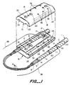
- FIG 1 illustrates a first preferred embodiment of the invention for providing an environmental block for a cable, preferably a loose tube or slotted core optical fiber cable, a slotted core cable 1 being shown in this figure.
- the optical fiber cable 1 has an outer sheath 2 surrounding a metal grounding shield 3 which in turn surrounds an inner sheath 4 which surrounds a slotted core 5 having helical grooves 9 on an outer surface thereof which guide a plurality of optical fibers 8 in the grooves.
- FIG 7 illustrates a similar optical fiber cable 11 having a similar outer sheath, metallic shield, inner sheath construction except that the cable 11 in FIG 7 is of the loose tube type wherein instead of the slotted core 5 the cable surrounds a plurality of loose tubes 10, with a plurality of optical fibers optimally being contained within each individual tube 10. Accordingly, it is tubes, rather than optical fibers, which are exposed when the various cable layers are stripped away and individually sealed as explained below.
- the cable 1, 11 is blocked by utilizing first and second half shell members 15, 16 which are engageable by aligning alignment pins 17 with alignment holes 18 and interengaging same.
- the half shell members are secured together utilizing bolts and nuts, or screws, which interengage the members through mating holes 20, 21.
- Each half shell member preferably has two longitudinally oriented stepped semicylindrical channels 24 therein which extend from a substantially planar face 25. The faces 25 mate and sealingly engage with each other and form a seal therebetween as described in more detail below.
- Each channel 24 optimally has a plurality of stepped channel portions, one portion for each cable layer to be successively sealed so as to form a water block regardless of which layer boundary may be contaminated and having a water flow longitudinally down the cable.
- the embodiment of FIG 1 illustrates three stepped substantially semicylindrical channel portions 31, 32, 33, again the precise number of channels being determined by the number of cable layers to which a seal is required.
- a plurality of electrical grounding pins 35 extend into one or more of the channel portions 31-33 radially a depth sufficient so as to make electrical contact with the metallic cable shield 3, and optimally an electrical lead wire (not shown) extends from a surface, e.g. back surface away from an optical fiber breakout portion of the cable, from the half shell members.
- the lead wire is preferably connected to an appropriate grounding medium.
- This construction safely protects the optical fiber cable (or other kinds of cable) from lightening strikes and other types of current surges.
- an environmental sealing tape 37 is helically wound around those portions of an outer surface of the cable which are to be environmentally sealed by the half shell members 15, 16.
- the tape 37 is gel impregnated and has thereon and therein a relatively soft elastic gel whose cone penetration is between 100 and 350 (10 ⁇ 1mm) and has an ultimate elongation of at least 100%, such gels and tapes being more fully described in USP 4,600,261; 4,634,207; 4,643,924; and 4,650,228.
- an intermediate portion of the exposed cable inner sheath is removed along a third section of the optical fiber which is collinear with the first and second sections except again shorter than both the first and second sections so as to result in a short portion of the inner cable sheath 4 being exposed and thus forming a third step 41 from which extends the slotted core 5 of the cable.
- an intermediate section of the exposed slotted core is removed which again is collinear with but shorter than the third section thus leaving the optical fibers 8 free and accessible along a substantial intermediate length thereof.
- the exact length of the exposed metallic shield 3 and inner sheath 4 is matched to the extent practical to a length of its corresponding channel portion 33, 32 respectively.
- the entire length of the various layered cable sections thus exposed and to be seated in the channel portions 31-33 is wrapped with the gel impregnated tape 37 in a helical fashion, as illustrated in FIG 1, and the layered and stripped cable at opposite sides of the fiber breakout portion is inserted into the semicylindrical channels 24 in the first and second half shell members as illustrated in FIG 1, and the half shell members are assembled using the alignment pins 17 and holes 18 and then secured together by utilizing bolts or other similar means in mating holes 20, 21.
- an inside diameter of each stepped channel portion 31, 32, 33 is only slightly larger than an outside diameter of each stepped cable portion 2, 3, 4 such that subsequent to wrapping the stepped cable portion with the gel impregnated tape the overall diameter of the cable plus tape is slightly larger than the insider diameter of the channel portions. Accordingly, when the half shell members are assembled as described, the gel is placed under a compressive load and is elastically resiliently urged around and within surfaces it contacts with a small amount of gel and/or gel tape being compressively urged and displaced between the mating faces 25 of the half shell members 15, 16 so as to form an excellent environmental cable barrier.
- FIG 7 The construction of FIG 7 is quite similar to that of FIG 1 except that in FIG 7 the optical fiber cable 1 has been replaced with an optical fiber cable 11 which is of the loose tube type wherein the major difference in the cable construction is the lack of a slotted core. Hence subsequent to removing the inner sheath 4 one or more plurality of loose tubes are finally exposed from an innermost cable core 29, with individual optical fibers 8 being contained within the hollow tubes 10. Portions of intermediate sections of the tubes 10 can then be removed as necessary to access individual optical fibers 8.
- the cable block of FIG 7 is functionally and operationally the same as that of FIG 1.
- the cable block as described by reference to FIGs 1 and 4 forms an excellent water block for an optical fiber cable having an intermediate section thereof which is to be entered so as to access optical fibers in the cable, preferably for optically coupling therewith using passive noninvasive couplers of the type described in any of USP 4,728,169; 4,741,585; 4,824,199; and U.S. application serial no. 252,915 filed September 30, 1988 and U.S. application serial no. 383,828 filed July 21, 1989.
- any type of conventional closure such as that disclosed in U.S. application serial no. 262,067 filed October 24, 1988, can be utilized for forming environmental seals around an exterior portion of the half shells 15, 16 and any electrical and/or power cables which are also required to enter the housing or exit therefrom.
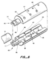
- the invention is further useful for environmentally blocking and protecting an end segment of an optical fiber cable such as can occur at an end termination, such as at an office interface unit where termination of optical fibers ultimately is to be made at a fiber distribution panel 45 as illustrated in FIG 5.
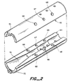
- a further preferred embodiment of the invention utilizes a member which again comprises mating first and second half shell members 64, 65 but which together form only one interior stepped longitudinal channel since it is only an end of the cable which is to be sealed, as shown in FIG 2.
- Each half shell member 64, 65 contains a pin 66 which engages a mating hole 67 on the other member so as to correctly seat the half shell members 64, 65 together, and they are secured thereto, like in the embodiment of FIG 1, with bolts or screws which extend through securing holes 68 with a substantially cylindrical shaped stepped channel being formed therebetween which tightly engages a gel wrapped stripped stepped cable (not shown in FIG 2).
- a pin 66 which engages a mating hole 67 on the other member so as to correctly seat the half shell members 64, 65 together, and they are secured thereto, like in the embodiment of FIG 1, with bolts or screws which extend through securing holes 68 with a substantially cylindrical shaped stepped channel being formed therebetween which tightly engages a gel wrapped stripped stepped cable (not shown in FIG 2).
- member 51 in FIG 3 has a central longitudinal and substantially cylindrical channel 52 which extends longitudinally part way through the member 51 and which receives an end portion of the exposed cable slotted core 5 and is securely attached thereto by set screws (not shown) which radially are inserted through the member 51 in holes 53 illustrated in FIG 3b.
- the member 51 is useable with first and second half shell members 64, 65 which have a similar construction to that of half shell members 15, 16 except that together the half shell members 64, 65 form only a single longitudinal stepped substantially cylindrical bore, as previously explained.
- An end of the half shell members 64, 65 preferably has extensions, e.g. pins 70, protruding therefrom longitudinally which align with and mate with corresponding holes 71 at an end of the member 51.
- a side 75 of the members 64, 65 where the exposed slotted core and fibers of the cable exit has an enlarging conical design as illustrated.
- the member 51 can easily be attached to the half shell members 64, 65, as illustrated in FIG 4 (which shows only part of the terminated cable), and the entire assembly, e.g. the members 51, 64, 65, and a portion of an unstripped cable entering into the half shell 64, 65 can be environmentally surrounded and protected by a heat shrinkable recoverable sleeve 72.
- FIG 3b further shows a cylindrical bore extending partially from an end face of the member 51 from a side opposite that of the bore 52 which accommodates the exposed portion of the slotted core, this element being identified by reference numeral 73.
- FIG 6 illustrates a preferred construction whereby first and second half shell members having a structure similar to that illustrated in FIG 2 is shown except that one end 85 of the half shells has a substantially reduced diameter section 77 through which loose tubes of the cable extend.
- a ridge 86 also extends upward from an outside surface of the reduced diameter section 77.
- the loose tubes containing optical fibers simply extend through the reduced diameter section 77, and to provide further environmental protection optionally a further tube 91 can be disposed over an exterior portion of the reduced section 77 and held thereon by the ridge 86 so as to further protect the loose tubes and the fibers contained therewithin.
- the tube 91 has a longitudinal channel therein and can optimally be slid over the exterior part of the one end 85 of the half shells and be secured thereto by the ridge 86 by a resilient tight fit. More specifically, the tube 91 can be made of a resilient rubber having a diameter substantially similar to that of the one end 85 so as to have to be stretched over the ridge 86 so as to form a friction fit therebetween.
Landscapes
- Physics & Mathematics (AREA)
- General Physics & Mathematics (AREA)
- Optics & Photonics (AREA)
- Cable Accessories (AREA)
- Laying Of Electric Cables Or Lines Outside (AREA)
- Communication Cables (AREA)
- Light Guides In General And Applications Therefor (AREA)
Claims (15)
- Telekommunikationskabelblock für ein Telekommunikationskabel, der aufweist:
ein Telekommunikationskabel (1, 11), das einen ersten Bereich hat, von dem ein Außen- und ein Innenmantel (2, 4) abisoliert sind, um einen Zwischenabschnitt des Innenmantels (4) entlang dem Kabel freizulegen und um eine Länge von Telekommunikationstransportmedien (8, 10), die von dem Kabel geschützt sind, freizulegen;
ein erstes und ein zweites in und außer Eingriff bringbares Element (15, 16, 64, 65), wobei die Elemente, wenn sie in Eingriff sind, mindestens einen ersten abgestuften, im wesentlichen zylindrischen Kanal bilden, der einen ersten und einen zweiten Längsbereich (32, 31) mit mindestens einer Stufe dazwischen hat, wobei der Abschnitt des Innenmantels (4) in dem ersten Kanalbereich (32) angeordnet ist und ein Abschnitt des Außenmantels (2) in dem zweiten Kanalbereich (31) angeordnet ist; und
eine Einrichtung, um das erste und das zweite Element zusammenzudrücken, um mit dem Innen- bzw. dem Außenmantel in dem ersten bzw. dem zweiten Kanalbereich abdichtend in Eingriff zu gelangen. - Kabelblock nach Anspruch 1, der ferner ein relativ weiches elastisches Gelband (37) aufweist, wobei das Band mit einem Gel imprägniert ist, das eine Konuspenetration zwischen 100 und 350 (10⁻¹ mm) und eine Bruchdehnung größer als mindestens 100 % hat, wobei das Gelband um das Kabel herumgewickelt ist, um sowohl mit einer Innenfläche des zylindrischen Kanals als auch mit einer Außenfläche des Kabels um einen Umfang von 360° herum in Kontakt zu sein.
- Kabelblock nach Anspruch 1 oder 2, wobei der Kabelbereich abisoliert ist, um einen Abschnitt einer metallischen Kabelabschirmung (3) zwischen einem Ende eines nichtabisolierten Teils des Außenmantels (2) und dem freigelegten Abschnitt des Innenmantels (4) freizulegen, wobei die freigelegte metallische Abschirmung in einem dritten Kanalbereich (33) angeordnet ist, der zwischen dem und angrenzend an den ersten und zweiten Kanalbereich liegt und durch Stufen davon getrennt ist, wobei eine Länge des dritten Kanalbereichs einer Länge der freigelegten metallischen Abschirmung im wesentlichen gleich ist, wobei der erste bzw. der zweite Kanalbereich entlang einer Länge davon von dem freigelegten Innenmantel bzw. dem Außenmantel im wesentlichen eingenommen ist, wobei bevorzugt ein Gel (37) in sämtlichen drei Kanalbereichen angeordnet ist und wobei das Kabel ein Lichtwellenleiterkabel mit geschlitztem Kern oder ein Losrohr-Lichtwellenleiterkabel aufweist.
- Kabelblock nach Anspruch 3, der ferner eine Einrichtung (35) aufweist, um die metallische Abschirmung (3) elektrisch zu verbinden, wobei die Verbindungseinrichtung in dem dritten Kanalbereich (33) angeordnet ist, um fähig zu sein, Elektrizität daraus und weg von dem ersten und dem zweiten Element zu einer elektrischen Masse zu leiten.
- Kabelblock nach Anspruch 4, wobei das erste und das zweite Element Halbschalenelemente aufweisen, die jeweils einen halbzylindrischen, abgestuften Längskanal darin haben, die gemeinsam den abgestuften, im wesentlichen zylindrischen Kanal bilden, wenn das erste und das zweite Element in Eingriff sind, wobei die Elemente zusammenpassende Ausfluchtungsstifte und -löcher aufweisen, die die Elemente miteinander ausfluchten, um ihren Eingriff zu erleichtern.
- Kabelblock nach Anspruch 5, der ferner ein drittes Element (51) aufweist, das ein Ende hat, das mit einem Ende des ersten und des zweiten Elements (64, 65) zusammenfügbar ist, wobei das erste, das zweite und das dritte Element Einrichtungen (70, 71) haben, um ihre jeweiligen Enden miteinander auszufluchten, wobei das dritte Element einen ersten Längskanal (52) hat, der es nur teilweise in Längsrichtung durchsetzt, wobei der erste Längskanal des dritten Elements einen kurzen Abschnitt eines freigelegten geschlitzten Kerns eines Lichtwellenleiterkabels aufnimmt, der sich von einem Ende des freigelegten Kabelinnenmantels erstreckt, wobei das dritte Element mindestens einen zweiten Längskanal (80) enthält, der sich im wesentlichen parallel zu seinem ersten Längskanal erstreckt, um Lichtwellenleiter aufzunehmen, die von einer Außenfläche des geschlitzten Kerns ausgehen.
- Kabelblock nach Anspruch 6, wobei das dritte Element mindestens einen in Radialrichtung verlaufenden Kanal (53) darin hat, der sich in eine Zwischenlänge des ersten Kanals des dritten Elements erstreckt, und ferner eine Einrichtung aufweist, die in dem in Radialrichtung verlaufenden Kanal angeordnet ist, um das dritte Element an dem geschlitzten Kern zu befestigen.
- Kabelblock nach Anspruch 6, der ferner eine Schutzhülle aufweist, die über einer Außenfläche mindestens eines Teils des dritten Elements, über einer vollständigen Außenfläche des ersten und des zweiten Elements und über einem Teil eines nichtabisolierten Teils des Kabelaußenmantels angeordnet ist.
- Kabelblock nach Anspruch 4, wobei das erste und das zweite Element gemeinsam einen Auslaßkanal (77) für eine Vielzahl von in dem Kabel enthaltenen losen Rohren aufweist, die freigelegt sind, nachdem das Kabel abisoliert ist, wobei eine Außenumfangsfläche des Auslaßkanals eine Umfangsrippe (86) darum herum hat, um ein rohrförmiges Element (91) auf einer Außenfläche des Auslaßkanals zu halten.
- Kabelblock nach Anspruch 1, wobei die Elemente, wenn sie in Eingriff sind, einen zweiten abgestuften Längskanal bilden, der eine Konstruktion hat, die der des ersten Kanals im wesentlichen gleich ist, um einen zweiten abisolierten Kabelbereich aufzunehmen und abzudichten, der eine Konstruktion hat, die der des ersten abisolierten Kabelbereichs im wesentlichen gleich, jedoch in Längsrichtung entlang dem Kabel davon verlagert ist, wobei die Telekommunikationsleitmedien zum leichten Zugang zwischen dem ersten und dem zweiten abisolierten Kabelbereich freigelegt sind.
- Kabelblock nach Anspruch 4, wobei die Elemente, wenn sie in Eingriff sind, einen zweiten abgestuften Längskanal bilden, der eine Konstruktion hat, die der des ersten Kanals im wesentlichen gleich ist, um einen zweiten abisolierten Kabelbereich aufzunehmen und abzudichten, der eine Konstruktion hat, die dem ersten abisolierten Kabelbereich im wesentlichen gleich, jedoch in Längsrichtung entlang dem Kabel davon verlagert ist, wobei die Telekommunikationsleitmedien zum leichten Zugang zwischen dem ersten und dem zweiten abisolierten Kabelbereich freigelegt sind.
- Lichtwellenleiterkabelblock für ein Lichtwellenleiterkabel, das Lichtwellenleiter darin enthält, wobei der Kabelblock aufweist:
ein Lichtwellenleiterkabel (1, 11), das mindestens einen Außenmantel (2) und einen Innenmantel (4) hat und in dem mindestens ein Lichtwellenleiter angeordnet ist, wobei von einem ersten Abschnitt des Kabels eine längs verlaufende Länge des Außenmantels (2) entfernt ist, um mindestens einen Kabelinnenmantel (4) darunter entlang einem zweiten Kabelabschnitt freizulegen, der kürzer als der erste Kabelabschnitt und damit kollinear ist;
ein erstes und ein zweites in und außer Eingriff bringbares Halbschalenelement (15, 16, 64, 65), wobei jedes Halbschalenelement mindestens einen längs verlaufenden, abgestuften, halbzylindrischen Kanal (24) darin enthält, der angeordnet ist, um sich von einer Oberfläche (25) jedes der Elemente, die miteinander in Eingriff bringbar sind, zu erstrecken, wobei die Elemente, wenn sie in Eingriff sind, mindestens einen längs verlaufenden, abgestuften, zylindrischen Kanal darin bilden, wobei ein erster (32) bzw. ein zweiter (31) Längsbereich des Kanals einen Stufendurchmesser hat, dessen Größe der des Kabelinnenmantels (4) bzw. des Kabelaußenmantels (2) gleich ist, wobei das erste und das zweite Halbschalenelement um das Kabel herum derart angeordnet sind, daß eine erste Länge des freigelegten Innenmantels in dem ersten Kanalbereich (32) angeordnet ist und ein nichtabisolierter Bereich des Kabels in dem zweiten Kanalbereich (31) angeordnet ist, wobei die erste Länge des Innenmantels kürzer als der zweite Kabelabschnitt ist;
eine Einrichtung, um das erste und das zweite Halbschalenelement zusammenzudrücken, um mit dem Innen- bzw. dem Außenmantel in dem ersten bzw. dem zweiten Kanalbereich abdichtend in Eingriff zu gelangen. - Kabelblock nach Anspruch 12, wobei eine Zwischenlänge des Kabelinnenmantels (4) entlang einem dritten Kabelabschnitt, der mit dem zweiten Kabelabschnitt kollinear, aber kürzer als dieser ist, entfernt ist, wobei der erste (32) und der zweite (31) Kabelbereich bevorzugt an entgegengesetzten Enden der Halbschalenelemente angeordnet sind, wobei der Kabelblock bevorzugt ferner ein relativ weiches elastisches Gelband aufweist, wobei das Band mit einem Gel imprägniert ist, das eine Konuspenetration zwischen 100 und 350 (10⁻¹ mm) und eine Bruchdehnung größer als mindestens 100 % hat, wobei das Gelband um das Kabel herumgewickelt ist, um sowohl mit einer Innenfläche des zylindrischen Kanals als auch mit einer Außenfläche des Kabels um einen Umfang von 360° herum in Kontakt zu sein.
- Kabelblock nach Anspruch 13, wobei das Kabel eine metallische Abschirmung (3) zwischen dem Innenmantel (4) und dem Außenmantel (2) aufweist, wobei eine Zwischenlänge der metallischen Abschirmung entlang einem vierten Kabelabschnitt, der mit dem ersten Kabelabschnitt kollinear, aber kürzer als dieser und länger als der zweite Kabelabschnitt ist, entfernt ist, wobei der längs verlaufende abgestufte Kanal einen dritten Längsbereich (33) hat, der zwischen dem ersten (32) und dem zweiten (31) Kanalbereich angeordnet ist, wobei eine Zwischenlänge der Abschirmung, die freigelegt ist, in dem dritten Kanallängsbereich angeordnet ist.
- Kabelblock nach Anspruch 14, der ferner eine Einrichtung (35) aufweist, um die metallische Abschirmung (3) elektrisch zu verbinden, wobei die Verbindungseinrichtung in dem dritten Kanalbereich (33) angeordnet ist, um fähig zu sein, Elektrizität daraus und weg von dem ersten und dem zweiten Halbschalenelement zu leiten, wobei die elektrische Verbindungseinrichtung eine Vielzahl von dünnen langgestreckten Elementen aufweist, die sich in Radialrichtung durch mindestens einen Teil eines der Halbschalenelemente erstrecken, um eine Ende zu haben, das in dem dritten Kanalbereich endet, um mit der metallischen Abschirmung in elektrischem Kontakt zu sein, wobei ein entgegengesetztes Ende der langgestreckten Elemente mit einer elektrischen Masse elektrisch verbunden ist.
Applications Claiming Priority (3)
| Application Number | Priority Date | Filing Date | Title |
|---|---|---|---|
| US399689 | 1989-08-28 | ||
| US07/399,689 US4978194A (en) | 1989-08-28 | 1989-08-28 | Stepped cable block |
| PCT/US1990/004656 WO1991003853A1 (en) | 1989-08-28 | 1990-08-17 | Stepped cable block |
Publications (2)
| Publication Number | Publication Date |
|---|---|
| EP0489824A1 EP0489824A1 (de) | 1992-06-17 |
| EP0489824B1 true EP0489824B1 (de) | 1995-01-25 |
Family
ID=23580588
Family Applications (1)
| Application Number | Title | Priority Date | Filing Date |
|---|---|---|---|
| EP90913374A Expired - Lifetime EP0489824B1 (de) | 1989-08-28 | 1990-08-17 | Abgestufter kabelblock |
Country Status (9)
| Country | Link |
|---|---|
| US (1) | US4978194A (de) |
| EP (1) | EP0489824B1 (de) |
| JP (1) | JPH04507489A (de) |
| KR (1) | KR920704391A (de) |
| AT (1) | ATE117852T1 (de) |
| AU (1) | AU642161B2 (de) |
| CA (1) | CA2065241A1 (de) |
| DE (1) | DE69016443T2 (de) |
| WO (1) | WO1991003853A1 (de) |
Families Citing this family (12)
| Publication number | Priority date | Publication date | Assignee | Title |
|---|---|---|---|---|
| US5048918A (en) * | 1990-02-07 | 1991-09-17 | Raychem Corporation | Optical fiber cable termination |
| US5073044A (en) * | 1990-10-31 | 1991-12-17 | Amp Incorporated | Right angle strain relief for optical fiber connector |
| US5187764A (en) * | 1991-04-25 | 1993-02-16 | Cablelite Corporation | Conduit for fiber optical cables |
| DE4226368A1 (de) * | 1992-08-09 | 1994-02-10 | Suhner Elektronik Gmbh | Übertragungsstrecke für mit Lichtwellenleitern bestückte Anlagen |
| US5305405A (en) * | 1993-02-25 | 1994-04-19 | Adc Telecommunications, Inc. | Patch cord |
| ES2100801B1 (es) * | 1994-05-05 | 1998-02-16 | Garcia Maurino De Vigo Luis | Mejoras introducidas en canalizaciones electricas modulares prefabricadas. |
| US5666453A (en) * | 1994-07-15 | 1997-09-09 | Roy Witte | Fiber optic jumper cables and tracing method using same |
| US5710851A (en) * | 1995-11-06 | 1998-01-20 | Amphenol Corporation | Strain relief system for a fiber optic connector |
| GB2352110A (en) * | 1999-07-14 | 2001-01-17 | Taiko Denki Co Ltd | Plastic optical fibre cables in a telecommunication exchange |
| US6743044B2 (en) * | 2002-08-14 | 2004-06-01 | Adc Telecommunications, Inc. | Cross-connect jumper assembly having tracer lamp |
| ES2435424T3 (es) * | 2009-02-10 | 2013-12-19 | Tyco Electronics Raychem Bvba | Dispositivo de protección de empalme para empalmes ópticos y conjunto de cables de fibras ópticas que lo incorpora |
| CN214041821U (zh) * | 2020-12-31 | 2021-08-24 | 惠州市飞博康实业有限公司 | 一种gh分支器 |
Family Cites Families (12)
| Publication number | Priority date | Publication date | Assignee | Title |
|---|---|---|---|---|
| FR2494856A1 (fr) * | 1980-11-27 | 1982-05-28 | Lignes Telegraph Telephon | Dispositif d'etancheite pour boitier de raccordement d'un cable sous enveloppe ondulee |
| US4744629A (en) * | 1985-08-16 | 1988-05-17 | Augat Inc. | Multifiber optical cable connector |
| JPS6270805A (ja) * | 1985-09-25 | 1987-04-01 | Furukawa Electric Co Ltd:The | 光・メタル複合ケ−ブル端末部 |
| US4746187A (en) * | 1985-10-07 | 1988-05-24 | The United States Of America As Represented By The Secretary Of The Navy | Kink-free fiber optic cable connector |
| FR2588670B1 (fr) * | 1985-10-16 | 1987-12-11 | Lignes Telegraph Telephon | Tete d'eclatement d'un cable a fibres optiques |
| JPS6276303U (de) * | 1985-10-31 | 1987-05-15 | ||
| JPH077139B2 (ja) * | 1985-12-24 | 1995-01-30 | 日本電信電話株式会社 | 浮動ホルダ型光コネクタ |
| FR2597616B1 (fr) * | 1986-04-17 | 1988-08-05 | Telecommunications Sa | Dispositif et procede d'epanouissement de fibres optiques sortant d'un cable a raccorder |
| US4772081A (en) * | 1986-09-15 | 1988-09-20 | Tsi Incorporated | Fiber optic connector assembly |
| US4834479A (en) * | 1986-12-11 | 1989-05-30 | American Telephone And Telegraph Company | High and low pressure fluidblock assembly |
| US4900118A (en) * | 1987-05-22 | 1990-02-13 | Furukawa Electric Co., Ltd. | Multiple-fiber optical component and method for manufacturing of the same |
| DE3729075A1 (de) * | 1987-09-01 | 1989-03-16 | Schmidt Feinmech | Steckverbindung fuer lichtleiter |
-
1989
- 1989-08-28 US US07/399,689 patent/US4978194A/en not_active Expired - Lifetime
-
1990
- 1990-08-17 AT AT90913374T patent/ATE117852T1/de not_active IP Right Cessation
- 1990-08-17 CA CA002065241A patent/CA2065241A1/en not_active Abandoned
- 1990-08-17 AU AU63349/90A patent/AU642161B2/en not_active Ceased
- 1990-08-17 WO PCT/US1990/004656 patent/WO1991003853A1/en not_active Ceased
- 1990-08-17 EP EP90913374A patent/EP0489824B1/de not_active Expired - Lifetime
- 1990-08-17 KR KR1019920700449A patent/KR920704391A/ko not_active Withdrawn
- 1990-08-17 JP JP2512513A patent/JPH04507489A/ja active Pending
- 1990-08-17 DE DE69016443T patent/DE69016443T2/de not_active Expired - Fee Related
Also Published As
| Publication number | Publication date |
|---|---|
| US4978194A (en) | 1990-12-18 |
| DE69016443T2 (de) | 1995-09-21 |
| WO1991003853A1 (en) | 1991-03-21 |
| KR920704391A (ko) | 1992-12-19 |
| ATE117852T1 (de) | 1995-02-15 |
| CA2065241A1 (en) | 1991-03-01 |
| EP0489824A1 (de) | 1992-06-17 |
| AU642161B2 (en) | 1993-10-14 |
| JPH04507489A (ja) | 1992-12-24 |
| DE69016443D1 (de) | 1995-03-09 |
| AU6334990A (en) | 1991-04-08 |
Similar Documents
| Publication | Publication Date | Title |
|---|---|---|
| US10036859B2 (en) | Cable termination assembly and method for connectors | |
| EP0489824B1 (de) | Abgestufter kabelblock | |
| US7280725B2 (en) | Fiber optic furcation tube and method | |
| EP1775610B1 (de) | Stecker für optische Fasern | |
| US4110550A (en) | Electrical connector with adaptor for paper-insulated, lead-jacketed electrical cables and method | |
| IE832036L (en) | Optic fibre connection system | |
| CA1133996A (en) | Adaptor for paper-insulated, lead-jacketed electrical cables | |
| US4314094A (en) | Cable seal splice enclosure | |
| CA1267009A (en) | Composite overhead stranded conductor having a filler between optical fibers and a protective tube | |
| JPS5939970B2 (ja) | 内部伝熱ジヤケツトを持つたスプライス・コネクタ | |
| JPS582816A (ja) | 架空電気伝送システム | |
| KR101245365B1 (ko) | 광전복합 팬아웃 케이블 | |
| EP2706635B1 (de) | Endkappe, Anordnung und Kit zum Abschließen eines Übertragungskabels | |
| WO1998028822A1 (en) | Mass shield termination connector | |
| CN121394026B (zh) | 一种分支器及复合缆结构 | |
| GB2075770A (en) | Improvements in or relating to cable glands | |
| US6621963B1 (en) | Submarine casing for a submarine optical cable | |
| JPH0253762B2 (de) | ||
| WO2016126480A1 (en) | Universal remote radio unit bird armored fiber optic cable assembly | |
| CN121394026A (zh) | 一种分支器及复合缆结构 | |
| JPS63143514A (ja) | 電力・光複合ケ−ブルの光ケ−ブル接続方法 | |
| JPS59116704A (ja) | 光フアイバ−ケ−ブルおよびその用途 | |
| HK29194A (en) | Fiber optic connection system | |
| HK1201330B (en) | Fiber optic plug | |
| JPS63292104A (ja) | 電力・光複合ケ−ルの光ケ−ブル接続部 |
Legal Events
| Date | Code | Title | Description |
|---|---|---|---|
| PUAI | Public reference made under article 153(3) epc to a published international application that has entered the european phase |
Free format text: ORIGINAL CODE: 0009012 |
|
| 17P | Request for examination filed |
Effective date: 19920226 |
|
| AK | Designated contracting states |
Kind code of ref document: A1 Designated state(s): AT BE CH DE DK ES FR GB IT LI NL SE |
|
| 17Q | First examination report despatched |
Effective date: 19940214 |
|
| GRAA | (expected) grant |
Free format text: ORIGINAL CODE: 0009210 |
|
| AK | Designated contracting states |
Kind code of ref document: B1 Designated state(s): AT BE CH DE DK ES FR GB IT LI NL SE |
|
| PG25 | Lapsed in a contracting state [announced via postgrant information from national office to epo] |
Ref country code: IT Free format text: LAPSE BECAUSE OF FAILURE TO SUBMIT A TRANSLATION OF THE DESCRIPTION OR TO PAY THE FEE WITHIN THE PRE;WARNING: LAPSES OF ITALIAN PATENTS WITH EFFECTIVE DATE BEFORE 2007 MAY HAVE OCCURRED AT ANY TIME BEFORE 2007. THE CORRECT EFFECTIVE DATE MAY BE DIFFERENT FROM THE ONE RECORDED.SCRIBED TIME-LIMIT Effective date: 19950125 Ref country code: BE Effective date: 19950125 Ref country code: CH Effective date: 19950125 Ref country code: NL Effective date: 19950125 Ref country code: LI Effective date: 19950125 Ref country code: AT Effective date: 19950125 Ref country code: ES Free format text: THE PATENT HAS BEEN ANNULLED BY A DECISION OF A NATIONAL AUTHORITY Effective date: 19950125 Ref country code: DK Effective date: 19950125 |
|
| REF | Corresponds to: |
Ref document number: 117852 Country of ref document: AT Date of ref document: 19950215 Kind code of ref document: T |
|
| REF | Corresponds to: |
Ref document number: 69016443 Country of ref document: DE Date of ref document: 19950309 |
|
| ET | Fr: translation filed | ||
| PG25 | Lapsed in a contracting state [announced via postgrant information from national office to epo] |
Ref country code: SE Effective date: 19950425 |
|
| REG | Reference to a national code |
Ref country code: CH Ref legal event code: PL |
|
| NLV1 | Nl: lapsed or annulled due to failure to fulfill the requirements of art. 29p and 29m of the patents act | ||
| PLBE | No opposition filed within time limit |
Free format text: ORIGINAL CODE: 0009261 |
|
| STAA | Information on the status of an ep patent application or granted ep patent |
Free format text: STATUS: NO OPPOSITION FILED WITHIN TIME LIMIT |
|
| 26N | No opposition filed | ||
| PGFP | Annual fee paid to national office [announced via postgrant information from national office to epo] |
Ref country code: GB Payment date: 19960808 Year of fee payment: 7 |
|
| PGFP | Annual fee paid to national office [announced via postgrant information from national office to epo] |
Ref country code: FR Payment date: 19960809 Year of fee payment: 7 |
|
| PG25 | Lapsed in a contracting state [announced via postgrant information from national office to epo] |
Ref country code: GB Free format text: LAPSE BECAUSE OF NON-PAYMENT OF DUE FEES Effective date: 19970817 |
|
| GBPC | Gb: european patent ceased through non-payment of renewal fee |
Effective date: 19970817 |
|
| PG25 | Lapsed in a contracting state [announced via postgrant information from national office to epo] |
Ref country code: FR Free format text: LAPSE BECAUSE OF NON-PAYMENT OF DUE FEES Effective date: 19980430 |
|
| REG | Reference to a national code |
Ref country code: FR Ref legal event code: ST |
|
| PGFP | Annual fee paid to national office [announced via postgrant information from national office to epo] |
Ref country code: DE Payment date: 20050930 Year of fee payment: 16 |
|
| PG25 | Lapsed in a contracting state [announced via postgrant information from national office to epo] |
Ref country code: DE Free format text: LAPSE BECAUSE OF NON-PAYMENT OF DUE FEES Effective date: 20070301 |