EP0489800B1 - Material handling apparatus - Google Patents
Material handling apparatus Download PDFInfo
- Publication number
- EP0489800B1 EP0489800B1 EP90912984A EP90912984A EP0489800B1 EP 0489800 B1 EP0489800 B1 EP 0489800B1 EP 90912984 A EP90912984 A EP 90912984A EP 90912984 A EP90912984 A EP 90912984A EP 0489800 B1 EP0489800 B1 EP 0489800B1
- Authority
- EP
- European Patent Office
- Prior art keywords
- opening
- work head
- control member
- charging hopper
- guide surface
- Prior art date
- Legal status (The legal status is an assumption and is not a legal conclusion. Google has not performed a legal analysis and makes no representation as to the accuracy of the status listed.)
- Expired - Lifetime
Links
Images


Classifications
-
- B—PERFORMING OPERATIONS; TRANSPORTING
- B65—CONVEYING; PACKING; STORING; HANDLING THIN OR FILAMENTARY MATERIAL
- B65F—GATHERING OR REMOVAL OF DOMESTIC OR LIKE REFUSE
- B65F3/00—Vehicles particularly adapted for collecting refuse
- B65F3/14—Vehicles particularly adapted for collecting refuse with devices for charging, distributing or compressing refuse in the interior of the tank of a refuse vehicle
- B65F3/20—Vehicles particularly adapted for collecting refuse with devices for charging, distributing or compressing refuse in the interior of the tank of a refuse vehicle with charging pistons, plates, or the like
- B65F3/208—Vehicles particularly adapted for collecting refuse with devices for charging, distributing or compressing refuse in the interior of the tank of a refuse vehicle with charging pistons, plates, or the like the charging pistons, plates or the like oscillating about a horizontal axis
Definitions
- This invention relates generally to material handling apparatus and more particularly, though not exclusively, to apparatus suitable for handling refuse.
- One type of known refuse handling apparatus includes a loading mechanism which feeds refuse to a holding receptacle whenever the refuse is compressed or compacted by a ram or press which forms part of the loading mechanism.
- Such apparatus is usually on a truck or like vehicle and can be used in the collection of domestic refuse. Examples of such devices are described in United States patent specification numbers 3874529, 3881613, 4050594, 4298306, 4637306 and 4786228. Devices of this type suffer from the disadvantage that they are generally complicated and, as a result, expensive and difficult to maintain.
- US-Patent No. 3 370 525 discloses a material handling apparatus according to the preamble of claim 1.
- This known apparatus comprises a baffle plate which is sloping from the forward to the rearward wall of the loading compartment of the apparatus the lower edge of the baffle plate being disposed in close proximity to the top surface of the control member throughout its moving path. If some rubbish is carried under the lower edge of the baffle plate or underneath the lower edge of the control member it is difficult to get out of the refuse collector.
- a material handling apparatus which is suitable for use with a holding receptacle the apparatus comprising a charging hopper having a first opening through which material can be loaded into the charging hopper and a second opening through which material can be discharged from the charging hopper said second opening being disposed below said first opening when the apparatus is in use, further including a control member having a work head which is mounted for movement within said charging hopper about a pivot axis which extends generally laterally with respect to the normal upright operative position of the apparatus, the control member being pivotally movable about the pivot axis between a first position in which the work head is spaced from and disposed above the second opening, and a second position in which the work head is adjacent or within the second opening and wherein said charging hopper comprises a curved guide surface therein which extends between said first and second opening so as to define a slide for directing material towards said second opening said curved guide surface being generally complementary to the arc of movement of the lower most part of the work head between said first and second
- the work head of the apparatus of the invention operates in a simple pendulum fashion and this in conjunction with the positioning of the openings enables material to pass under the influence of gravity from the first opening towards the second opening.
- the arrangement is such that pivotal movement of the work head from the first to the second position causes material within the hopper to be pushed by the work head through the second opening.
- the material discharged through the second opening from the hopper is arranged to enter the holding receptacle and is capable of being compacted within the holding receptacle by the work head.
- the arrangement greatly assists in ensuring that material which is fed to the apparatus via the first opening is efficiently transferred to the second opening.
- the hopper may take any suitable form and in one advantageous arrangement comprises a side wall and a base wall with the first opening being in a top portion of the charging hopper and the second opening being disposed in the side wall in a region adjacent the base wall at a lower section thereof.
- the base wall may have the curved guide surface thereon.
- the control member may be arranged to pivot about the pivot axis which in one form is disposed above the second opening and generally in the same vertical plane.
- the control member may further include mounting arms which have the work head operatively connected to one thereof the other ends being mounted for pivotal movement about the pivot axis the mounting arms being arranged so that in said first position the first opening can be accessed. This can be as a result of the tapering of the work head towards its trailing edge which permits the first opening to be substantially clear of the work head even when the work head is in the first position.
- the top well is displaced in such a manner that it is adjacent one of the side walls of the hopper.
- the top wall of the work head may form a cover above the second opening when the control member is in the second position so that material being loaded into the charging hopper will not interfere with the material being discharged through the second opening and when the work head is in the first position, the top wall is displaced in such a manner that it is adjacent one of the side walls of the hopper.
- Drive means may be provided for causing movement of the control member between the first and second positions.
- Such drive means may be in the form of one or more hydraulic pistons/cylinder assemblies operatively interconnected between the mounting arms and the hopper.
- the piston/cylinder assemblies may be mounted on suitable pivot pins on the hopper and the mounting arms.
- the apparatus according to the present invention end the holding receptacle with which it may be associated when in use, are in one form, mounted on a vehicle such as a truck or the like. In another arrangement the apparatus of the present invention may be used with a static holding receptacle.
- Material such as refuse can be loaded into the hopper through the first opening thereof. With the control member in the first or raised position the material falls onto the guide surface on the base of the hopper and is directed towards the second opening from where it passes into the holding receptacle.
- Activation of the drive means causes the control member to move from the first position where the work head is raised to the second position where it is disposed adjacent the second opening and thereby forcing the material into the holding receptacle and when necessary compacting or compressing the material.
- the top wall of the work head forms a barrier between the major interior of the hopper and the second opening thereby ensuring that any material deposited in the hopper with the control member in the second position does not interfere with the compressing action of the work head.
- the apparatus of the present invention provides a relatively simple and efficient mechanism which because of its simplicity has relatively low maintenance.
- gravity therefor assists in moving the material towards the second opening for compacting the material within the holding receptacle when the work head is lowered.
- the apparatus generally indicated at 1 is shown mounted adjacent a collecting receptacle 50 in the form of a reinforced tank.
- the apparatus and receptacle may be mounted on a vehicle such as a truck 55.
- a loading arm 56 is arranged to pick up refuse bins and discharge the contents through chute 57 to the apparatus of the present invention.
- the receptacle is mounted onto a vehicle but may simply be disposed in a suitable location.
- the apparatus 1 includes a charging hopper 3 having a side wall 5 with a first opening 6 in its top and a second opening 7 in a lower region of the side wall 5.
- the hopper further includes a base wall 8 having a curved surface 9, which forms a slide directed from the first opening 6 towards the second opening 7.
- material from chute 57 is directed through the first opening 6 of the apparatus and material is passed through the second opening 7 into receptacle 50.
- the apparatus 1 further includes a control member 10 having a work head 12 disposed within the charging hopper 3 the control member 10 being mounted for movement about a pivot axis 20 which extends generally horizontally as shown.
- the work head 12 moves in an arc about the pivot axis 20 between a first or raised position in which the work head 12 is spaced from the second opening 7 and a second or lowered position in which the work head 12 is adjacent or within the second opening.
- the work head 12, as shown is in the form of a block having a front wall 14 a top wall 15 and side walls 16.
- the front wall 14 is arranged to push the material in the charging hopper 3 through the second opening 7 and where necessary compact the material within the receptacle 50.
- the side walls 16 of the work head each have a curved lower edge 17 which is complementary to the curved guide surface 9 of the charging hopper 3 the curved lower edges 17 of the side wall of the work head being adjacent the curved guide surface of the charging hopper.
- the top wall 15 and side walls 16 converge towards one another in the direction of the trailing edge of work head 12.
- the work head does not interfere with opening 6 of the charging hopper 3.
- the control member 10 further includes a pair of mounting arms 18 which have the work head 12 operatively connected to one thereof the other ends being mounted for pivotal movement about the pivot axis 20 in suitable bearings 19.
- the mounting arms 18 are disposed at the sides of the work head so as to ensure a minimum of interference at the first opening 6.
- the top wall 15 of the work head 12 forms a cover above the second opening 7 when the control member is in the lowered or second position so that material being loaded into the hopper through opening 6 will not interfere with the material being discharged through the second opening.
- the top wall when the work head 12 is in the first or raised position, the top wall positioned such that it is adjacent the side wall of the charging hopper 3. This is achieved because of the tapering configuration of side walls 16.
- Drive means 25 causes movement of the control member 10 between the first and second positions.
- the drive means 25 is in the form of hydraulic pistons/cylinder assemblies 27 operatively interconnected between the mounting arms 18 and the charging hopper 3.
- the piston/cylinder assemblies 27 are mounted on pivot pins 28 and 29 on the charging hopper 3 and the mounting arms 18 respectively.
- material such as refuse can be loaded into the charging hopper 3 through the first opening 6 thereof.
- the control member 10 With the control member 10 in the first or raised position the material falls onto the curved guide surface on the base of the charging hopper 3 and under the influence of gravity is directed towards the second opening 7 from where it passes into the holding receptacle 50.
- Activation of the drive means 25 causes the control member 10 to move from the first position where the work head 12 is raised to the second position where it is disposed adjacent the second opening 7 and thereby forcing the material into the holding receptacle and when necessary compacting or compressing the material.
- the top wall 15 of the work head 12 forms a barrier over the second opening 7 thereby ensuring that any material deposited in the charging hopper 3 with the control member in the second position does not interfere with the compressing action of the work head.
- the apparatus of the present invention provides a relatively simple and efficient mechanism which because of its simplicity has relatively low maintenance.
- gravity therefor assists in moving the material through the second opening and compacting the material within the receptacle.
Landscapes
- Engineering & Computer Science (AREA)
- Mechanical Engineering (AREA)
- Filling Or Emptying Of Bunkers, Hoppers, And Tanks (AREA)
- Control And Other Processes For Unpacking Of Materials (AREA)
- Manipulator (AREA)
- Non-Silver Salt Photosensitive Materials And Non-Silver Salt Photography (AREA)
- Feeding Of Articles To Conveyors (AREA)
Abstract
Description
- This invention relates generally to material handling apparatus and more particularly, though not exclusively, to apparatus suitable for handling refuse.
- One type of known refuse handling apparatus includes a loading mechanism which feeds refuse to a holding receptacle whenever the refuse is compressed or compacted by a ram or press which forms part of the loading mechanism. Such apparatus is usually on a truck or like vehicle and can be used in the collection of domestic refuse. Examples of such devices are described in United States patent specification numbers 3874529, 3881613, 4050594, 4298306, 4637306 and 4786228. Devices of this type suffer from the disadvantage that they are generally complicated and, as a result, expensive and difficult to maintain.
- US-Patent No. 3 370 525 discloses a material handling apparatus according to the preamble of claim 1. This known apparatus comprises a baffle plate which is sloping from the forward to the rearward wall of the loading compartment of the apparatus the lower edge of the baffle plate being disposed in close proximity to the top surface of the control member throughout its moving path. If some rubbish is carried under the lower edge of the baffle plate or underneath the lower edge of the control member it is difficult to get out of the refuse collector.
- It is an object of the present invention to provide an improved material handling appartus which is relatively simple in construction and has relatively low maintenance.
- According to the present invention there is provided a material handling apparatus which is suitable for use with a holding receptacle the apparatus comprising a charging hopper having a first opening through which material can be loaded into the charging hopper and a second opening through which material can be discharged from the charging hopper said second opening being disposed below said first opening when the apparatus is in use, further including a control member having a work head which is mounted for movement within said charging hopper about a pivot axis which extends generally laterally with respect to the normal upright operative position of the apparatus, the control member being pivotally movable about the pivot axis between a first position in which the work head is spaced from and disposed above the second opening, and a second position in which the work head is adjacent or within the second opening and wherein said charging hopper comprises a curved guide surface therein which extends between said first and second opening so as to define a slide for directing material towards said second opening said curved guide surface being generally complementary to the arc of movement of the lower most part of the work head between said first and second positions, said work head being disposed adjacent said guide surface and in close proximity thereto during movement between said first and second positions characterized in that the work head comprises a top surface and a lower surface, which taper towards one another to form a rear edge section of a reduced height wherein the lower surface is curved to substantially the same arc as said guide surface and wherein the top surface is shaped to act as a sloping surface when said work head is in said first position to guide material towards the second opening and that said work head is in the form of a block having a front wall, said top surface, said lower surface and side walls, said front wall being arranged to push the material through the second opening and where necessary compact the material within the receptacle, said side walls having a curved lower edge which is curved complementary to the curved guide surface, the curved lower edges of the side walls and said lower surface of the control member being adjacent the curved guide surface of the charging hopper whereby when the control member moves from the second position to the first position the leading rear edge section of the control member defined by the end of said top surface most remote from the front wall and said lower surface will tend to scrape material off said guide surface into said top surface.
- Thus the work head of the apparatus of the invention operates in a simple pendulum fashion and this in conjunction with the positioning of the openings enables material to pass under the influence of gravity from the first opening towards the second opening.
- The arrangement is such that pivotal movement of the work head from the first to the second position causes material within the hopper to be pushed by the work head through the second opening. When the apparatus is in use with a holding receptacle the material discharged through the second opening from the hopper is arranged to enter the holding receptacle and is capable of being compacted within the holding receptacle by the work head.
- The arrangement greatly assists in ensuring that material which is fed to the apparatus via the first opening is efficiently transferred to the second opening.
- The hopper may take any suitable form and in one advantageous arrangement comprises a side wall and a base wall with the first opening being in a top portion of the charging hopper and the second opening being disposed in the side wall in a region adjacent the base wall at a lower section thereof. The base wall may have the curved guide surface thereon. The control member may be arranged to pivot about the pivot axis which in one form is disposed above the second opening and generally in the same vertical plane.
- The control member may further include mounting arms which have the work head operatively connected to one thereof the other ends being mounted for pivotal movement about the pivot axis the mounting arms being arranged so that in said first position the first opening can be accessed. This can be as a result of the tapering of the work head towards its trailing edge which permits the first opening to be substantially clear of the work head even when the work head is in the first position. When the work head is in the first or raised position, the top well is displaced in such a manner that it is adjacent one of the side walls of the hopper.
- The top wall of the work head may form a cover above the second opening when the control member is in the second position so that material being loaded into the charging hopper will not interfere with the material being discharged through the second opening and when the work head is in the first position, the top wall is displaced in such a manner that it is adjacent one of the side walls of the hopper.
- Drive means may be provided for causing movement of the control member between the first and second positions. Such drive means may be in the form of one or more hydraulic pistons/cylinder assemblies operatively interconnected between the mounting arms and the hopper. The piston/cylinder assemblies may be mounted on suitable pivot pins on the hopper and the mounting arms.
- The apparatus according to the present invention end the holding receptacle with which it may be associated when in use, are in one form, mounted on a vehicle such as a truck or the like. In another arrangement the apparatus of the present invention may be used with a static holding receptacle.
- The operation of the apparatus in its preferred form will hereinafter be described.
- Material such as refuse can be loaded into the hopper through the first opening thereof. With the control member in the first or raised position the material falls onto the guide surface on the base of the hopper and is directed towards the second opening from where it passes into the holding receptacle.
- Activation of the drive means causes the control member to move from the first position where the work head is raised to the second position where it is disposed adjacent the second opening and thereby forcing the material into the holding receptacle and when necessary compacting or compressing the material.
- In the second or lowered position the top wall of the work head forms a barrier between the major interior of the hopper and the second opening thereby ensuring that any material deposited in the hopper with the control member in the second position does not interfere with the compressing action of the work head.
- Further activation of the drive means causes the control member to return to the first position where the operation can be repeated.
- It will be appreciated from the foregoing that the apparatus of the present invention provides a relatively simple and efficient mechanism which because of its simplicity has relatively low maintenance. In a preferred form because the work head moves between a raised and lowered position gravity therefor assists in moving the material towards the second opening for compacting the material within the holding receptacle when the work head is lowered.
- Preferred embodiments of the invention will hereinafter be described with reference to the accompanying drawings in which:-
- Figure 1 is a schematic view of a refuse collecting vehicle incorporating apparatus according to the present invention;
- Figure 2 is a side elevation of apparatus according to the present invention;
- Figure 3 is a plan view of the apparatus as shown in Figure 2;
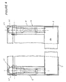
- Figure 4 is an end elevation of the apparatus shown in Figures 2 and 3; and
- Figure 5 is a schematic perspective view of a control member which forms part of the apparatus shown in figures 2 to 4.
- Referring to the drawings the apparatus generally indicated at 1 is shown mounted adjacent a collecting
receptacle 50 in the form of a reinforced tank. The apparatus and receptacle may be mounted on a vehicle such as atruck 55. Aloading arm 56 is arranged to pick up refuse bins and discharge the contents through chute 57 to the apparatus of the present invention. As mentioned earlier it is not necessary that the receptacle is mounted onto a vehicle but may simply be disposed in a suitable location. - As best seen in figures 2 to 5, the apparatus 1 includes a
charging hopper 3 having aside wall 5 with a first opening 6 in its top and a second opening 7 in a lower region of theside wall 5. The hopper further includes abase wall 8 having a curved surface 9, which forms a slide directed from the first opening 6 towards thesecond opening 7. In the particular application shown in figure 1, material from chute 57 is directed through the first opening 6 of the apparatus and material is passed through thesecond opening 7 intoreceptacle 50. - The apparatus 1 further includes a
control member 10 having awork head 12 disposed within thecharging hopper 3 thecontrol member 10 being mounted for movement about apivot axis 20 which extends generally horizontally as shown. Thework head 12 moves in an arc about thepivot axis 20 between a first or raised position in which thework head 12 is spaced from the second opening 7 and a second or lowered position in which thework head 12 is adjacent or within the second opening. - The
work head 12, as shown is in the form of a block having a front wall 14 atop wall 15 andside walls 16. In operation thefront wall 14 is arranged to push the material in thecharging hopper 3 through thesecond opening 7 and where necessary compact the material within thereceptacle 50. - The
side walls 16 of the work head each have a curvedlower edge 17 which is complementary to the curved guide surface 9 of the charging hopper 3 the curvedlower edges 17 of the side wall of the work head being adjacent the curved guide surface of the charging hopper. As best seen in figure 2 thetop wall 15 andside walls 16 converge towards one another in the direction of the trailing edge ofwork head 12. Thus when in the raised position as shown in figure 2, the work head does not interfere with opening 6 of thecharging hopper 3. - The
control member 10 further includes a pair of mountingarms 18 which have thework head 12 operatively connected to one thereof the other ends being mounted for pivotal movement about thepivot axis 20 in suitable bearings 19. The mountingarms 18 are disposed at the sides of the work head so as to ensure a minimum of interference at the first opening 6. - The
top wall 15 of thework head 12 forms a cover above the second opening 7 when the control member is in the lowered or second position so that material being loaded into the hopper through opening 6 will not interfere with the material being discharged through the second opening. As best seen in figure 2, when thework head 12 is in the first or raised position, the top wall positioned such that it is adjacent the side wall of thecharging hopper 3. This is achieved because of the tapering configuration ofside walls 16. - Drive means 25 causes movement of the
control member 10 between the first and second positions. As shown, the drive means 25 is in the form of hydraulic pistons/cylinder assemblies 27 operatively interconnected between the mountingarms 18 and thecharging hopper 3. The piston/cylinder assemblies 27 are mounted onpivot pins charging hopper 3 and the mountingarms 18 respectively. - In operation material such as refuse can be loaded into the
charging hopper 3 through the first opening 6 thereof. With thecontrol member 10 in the first or raised position the material falls onto the curved guide surface on the base of thecharging hopper 3 and under the influence of gravity is directed towards thesecond opening 7 from where it passes into theholding receptacle 50. - Activation of the drive means 25 causes the
control member 10 to move from the first position where thework head 12 is raised to the second position where it is disposed adjacent thesecond opening 7 and thereby forcing the material into the holding receptacle and when necessary compacting or compressing the material. - In the second or lowered position the
top wall 15 of thework head 12 forms a barrier over thesecond opening 7 thereby ensuring that any material deposited in thecharging hopper 3 with the control member in the second position does not interfere with the compressing action of the work head. - Further activation of the drive means causes the control member to return to the first position where the operation can be repeated.
- It will be appreciated from the foregoing that the apparatus of the present invention provides a relatively simple and efficient mechanism which because of its simplicity has relatively low maintenance. In a preferred form because the work head moves between a raised and lowered position gravity therefor assists in moving the material through the second opening and compacting the material within the receptacle.
Claims (6)
- Material handling apparatus which is suitable for use with a holding receptacle the apparatus comprising a charging hopper (3) having a first opening (6) through which material can be loaded into the charging hopper (3) and a second opening (7) through which material can be discharged from the charging hopper (3), said second opening (7) being disposed below said first opening (6) when the apparatus is in use, further including a control member (10) having a work head (12) which is mounted for movement within said charging hopper (3) about a pivot axis (20) which extends generally laterally with respect to the normal upright operative position of the apparatus, the control member (10) being pivotally movable about the pivot axis (20) between a first position in which the work head (12) is spaced from and disposed above the second opening (7), and a second position in which the work head is adjacent or within the second opening (7) and wherein said charging hopper (3) comprises a curved guide surface (9) therein which extends between said first and second opening (6, 7) so as to define a slide for directing material towards said second opening (7) said curved guide surface (9) being generally complementary to the arc of movement of the lower most part of the work head (12) between said first and second positions, said work head (12) being disposed adjacent said guide surface (9) and in close proximity thereto during movement between said first and second positions characterised in that the work head (12) comprises a top surface (15) of said work head, and a lower surface, which taper towards one another to form a rear edge section of a reduced height wherein the lower surface is curved to substantially the same arc as said guide surface and wherein the top surface is shaped to act as a sloping surface when said work head (12) is in said first position to guide material towards the second opening (7) and that said work head is in the form of a block having a front wall (14), said top surface (15), said lower surface and side walls (16), said front wall (14) being arranged to push the material through the second opening (7) and where necessary compact the material within the receptacle, said side walls (16) having a curved lower edge (17) which is curved complementary to the curved guide surface (9), the curved lower edges (17) of the side walls (16) and said lower surface of the control member being adjacent the curved guide surface (9) of the charging hopper (3) whereby when the control member (10) moves from the second position to the first position the leading rear edge section of the control member defined by the end of said top surface most remote from the front wall (14) and said lower surface will tend to scrape material off said guide surface (9) onto said top surface (15).
- Material handling apparatus according to Claim 1, wherein said charging hopper (3) comprises a side wall (5) and a base wall (8) with the first opening (6) being in a top portion of the charging hopper (3) and the second opening (7) being disposed in the side wall (5) in a region adjacent the base wall (8), said base wall having said curved guide surface (9) thereon.
- Material handling apparatus according to Claim 1, wherein said control member (10) further includes mounting arms (18) which have the work head (12) operatively connected to one end thereof, the other ends of said mounting arms being mounted for pivotal movement about the pivot axis (20), said mounting arms (18) being arranged so that in said first position the first opening can be accessed.
- Material handling apparatus according to Claim 3, wherein the top surface (15) of the work head (12) forms a cover above the second opening (7) when the control member (10) is in the second position so that material being loaded into the charging hopper (3) through the first opening (6) will not interfere with the material being discharged through the second opening (7), and when the work head is in the first position, the top surface (15) is displaced in such a manner that it is adjacent one of the side walls of the hopper.
- Material handling apparatus according to Claim 3, further including drive means (25) for causing movement of the control member (10) and comprising one or more hydraulic piston and cylinder (27) assemblies operatively interconnected between the mounting arms (18) and the charging hopper (3).
- Material handling apparatus as claimed in Claim 1, wherein the arcuate length of the control member (10) adjacent said guide surface (9) is less than half the arcuate swing of the control member (10) between the first position and the second position whereby all parts of the guide surface (9) between the first position and the second position can be exposed for cleaning.
Applications Claiming Priority (3)
| Application Number | Priority Date | Filing Date | Title |
|---|---|---|---|
| AU6097/89 | 1989-09-01 | ||
| AUPJ609789 | 1989-09-01 | ||
| PCT/AU1990/000386 WO1991003412A1 (en) | 1989-09-01 | 1990-08-30 | Material handling apparatus |
Publications (3)
| Publication Number | Publication Date |
|---|---|
| EP0489800A1 EP0489800A1 (en) | 1992-06-17 |
| EP0489800A4 EP0489800A4 (en) | 1992-08-19 |
| EP0489800B1 true EP0489800B1 (en) | 1995-01-18 |
Family
ID=3774155
Family Applications (1)
| Application Number | Title | Priority Date | Filing Date |
|---|---|---|---|
| EP90912984A Expired - Lifetime EP0489800B1 (en) | 1989-09-01 | 1990-08-30 | Material handling apparatus |
Country Status (7)
| Country | Link |
|---|---|
| US (1) | US5324161A (en) |
| EP (1) | EP0489800B1 (en) |
| AT (1) | ATE117268T1 (en) |
| AU (1) | AU649408B2 (en) |
| DE (1) | DE69016207T2 (en) |
| DK (1) | DK0489800T3 (en) |
| WO (1) | WO1991003412A1 (en) |
Families Citing this family (19)
| Publication number | Priority date | Publication date | Assignee | Title |
|---|---|---|---|---|
| CA2143852C (en) * | 1992-09-04 | 2004-06-15 | Ralph H. Ratledge, Jr. | Apparatus for packing separated recyclable materials |
| CA2170215C (en) * | 1995-03-28 | 2001-12-04 | Ronald E. Christenson | Tilting bin handler |
| US6095744A (en) * | 1997-01-15 | 2000-08-01 | Harrison; Ralph | Refuse container handling system |
| US6158336A (en) * | 1999-02-22 | 2000-12-12 | Cambiano; Angelo M. | Trash compacting container including guide plate |
| US6854949B2 (en) | 2002-04-30 | 2005-02-15 | Wittke Inc. | Refuse collection vehicle with pendular packing device and refuse ejection system |
| CA2413470A1 (en) * | 2002-12-03 | 2004-06-03 | Gabe Tomassoni | Side loading refuse vehicle with combined compactor |
| US6776570B1 (en) * | 2003-05-06 | 2004-08-17 | Michael Thobe | Refuse receptacle having a charging hopper and moving floor and method therefor |
| CA2439861A1 (en) * | 2003-09-05 | 2005-03-05 | Fanotech Enviro Inc. | Non-linear reciprocating packing mechanism for refuse collection vehicle |
| US20080035176A1 (en) * | 2004-08-25 | 2008-02-14 | Byers Ernest F | Automated Cart and Container Cleaning System |
| US20080105474A1 (en) * | 2004-08-25 | 2008-05-08 | Blast N Clean Llc | Cart and container cleaning system with heated fluid |
| US20080105761A1 (en) * | 2004-08-25 | 2008-05-08 | Blast N Clean Llc | Interior and exterior cleaning of waste carts and containers |
| US20080110476A1 (en) * | 2004-08-25 | 2008-05-15 | Blast N Clean Llc | Container cleaning system using nozzles |
| US7588408B2 (en) * | 2005-11-30 | 2009-09-15 | Fanotech Enviro Inc. | Waste packing apparatus and waste collection vehicle |
| DE102010039297A1 (en) * | 2010-08-13 | 2012-02-16 | Sib Strautmann Ingenieurbüro Gmbh | Pressing device of a collecting container |
| CN102259742A (en) * | 2011-05-16 | 2011-11-30 | 东莞市达成机械设备制造有限公司 | Swing-arm type garbage compression plant |
| US9555964B2 (en) * | 2014-04-24 | 2017-01-31 | Mytmule, Llc | Material handling system |
| CN104890279B (en) * | 2015-04-30 | 2017-10-13 | 海门市创豪工业设计有限公司 | A kind of pendulum compressed movable refuse compaction equipment |
| US9764894B2 (en) | 2015-08-25 | 2017-09-19 | Wayne Industrial Holdings, Llc | Refuse collection vehicle body with pendulum packer |
| CN111924388A (en) * | 2020-09-07 | 2020-11-13 | 山西明德环境科技有限公司 | Garbage compression, collection and transfer device |
Family Cites Families (22)
| Publication number | Priority date | Publication date | Assignee | Title |
|---|---|---|---|---|
| FR1064242A (en) * | 1952-10-09 | 1954-05-12 | Sovel Soc | Device for packing materials in a box |
| US2836316A (en) * | 1955-05-12 | 1958-05-27 | Edwin A Schonrock | Bulk material compactor for refuse trucks |
| US2879906A (en) * | 1957-01-22 | 1959-03-31 | Gar Wood Ind Inc | Refuse loader |
| US2914205A (en) * | 1957-10-07 | 1959-11-24 | Edward J Trubinski | Compartmented dump truck |
| US3130845A (en) * | 1961-05-19 | 1964-04-28 | Dempster Brothers Inc | Front end loaders |
| US3220586A (en) * | 1963-08-26 | 1965-11-30 | Leach Corp | Refuse collecting and transporting vehicle |
| US3370525A (en) * | 1965-09-24 | 1968-02-27 | Samuel V. Bowles | Interchangeable refuse truck body with self-loading mechanism |
| FR2045137A5 (en) * | 1969-06-06 | 1971-02-26 | Sovel | |
| JPS5243289B2 (en) * | 1973-02-19 | 1977-10-29 | ||
| US3881407A (en) * | 1973-07-16 | 1975-05-06 | James D Goar | Waste reduction equipment |
| US3874529A (en) * | 1974-05-31 | 1975-04-01 | Leach Corp | Refuse loading apparatus |
| US4042133A (en) * | 1975-06-06 | 1977-08-16 | Sargent Industries, Inc. | Refuse compactor |
| US4050594A (en) * | 1975-10-20 | 1977-09-27 | Leach Company | Refuse loading apparatus |
| FR2373462A1 (en) * | 1976-12-10 | 1978-07-07 | Konstruktiewerkhuizen Vandeker | IMPROVEMENTS AT THE DUMP TRUCKS |
| FR2436092A1 (en) * | 1978-09-18 | 1980-04-11 | Ctia | IMPROVEMENT IN SOLID LOAD COLDING SYSTEMS IN A RECEPTACLE |
| US4876228A (en) * | 1981-11-21 | 1989-10-24 | Mobil Oil Corporation | Zeolite modifications |
| DE3212209A1 (en) * | 1982-04-01 | 1983-10-06 | Abt Vertriebsgesellschaft Fuer | Press part for waste materials |
| DE3345758C2 (en) * | 1983-12-17 | 1985-10-10 | Schörling GmbH & Co Waggonbau, 3000 Hannover | Garbage truck |
| FR2576292B2 (en) * | 1984-05-23 | 1988-01-29 | Bricaud Jean Paul | SKIPPER IMPROVEMENT FOR COMPACTABLE PRODUCTS |
| FR2591203B1 (en) * | 1985-12-11 | 1990-08-31 | Nettoiement Ste Normande | DUMP FOR COLLECTION OF GARBAGE AND SIMILAR PRODUCTS. |
| EP0336003A3 (en) * | 1988-04-08 | 1990-06-20 | SCHÖRLING GMBH & CO. WAGGONBAU | Refuse vehicle |
| US4954020A (en) * | 1989-03-13 | 1990-09-04 | The Heil Co. | Apparatus for loading materials into a storage compartment |
-
1990
- 1990-08-30 AU AU62838/90A patent/AU649408B2/en not_active Expired
- 1990-08-30 DK DK90912984.3T patent/DK0489800T3/en not_active Application Discontinuation
- 1990-08-30 WO PCT/AU1990/000386 patent/WO1991003412A1/en active IP Right Grant
- 1990-08-30 AT AT90912984T patent/ATE117268T1/en not_active IP Right Cessation
- 1990-08-30 US US07/836,300 patent/US5324161A/en not_active Expired - Lifetime
- 1990-08-30 DE DE69016207T patent/DE69016207T2/en not_active Expired - Lifetime
- 1990-08-30 EP EP90912984A patent/EP0489800B1/en not_active Expired - Lifetime
Also Published As
| Publication number | Publication date |
|---|---|
| US5324161A (en) | 1994-06-28 |
| DE69016207T2 (en) | 1995-07-27 |
| EP0489800A4 (en) | 1992-08-19 |
| EP0489800A1 (en) | 1992-06-17 |
| DK0489800T3 (en) | 1995-06-19 |
| AU649408B2 (en) | 1994-05-26 |
| AU6283890A (en) | 1991-04-08 |
| WO1991003412A1 (en) | 1991-03-21 |
| DE69016207D1 (en) | 1995-03-02 |
| ATE117268T1 (en) | 1995-02-15 |
Similar Documents
| Publication | Publication Date | Title |
|---|---|---|
| EP0489800B1 (en) | Material handling apparatus | |
| US6146079A (en) | Dual blade packer system for refuse collection vehicle | |
| CA2143852C (en) | Apparatus for packing separated recyclable materials | |
| US5484246A (en) | Collecting, hauling and delivering apparatus for recyclable materials | |
| DE3537546C2 (en) | ||
| WO1994005570A9 (en) | Apparatus for packing separated recyclable materials | |
| US6776570B1 (en) | Refuse receptacle having a charging hopper and moving floor and method therefor | |
| US4316695A (en) | Garbage compaction truck | |
| US3815765A (en) | Material transport | |
| US3767068A (en) | Packer blade for a rear loader refuse vehicle | |
| JPS5943702A (en) | Garbage tamping device for garbage wagon | |
| GB1582698A (en) | Refuse collection vehicles | |
| US3966096A (en) | Satellite refuse packer | |
| US5352084A (en) | Refuse carrier for recyclable and non-recyclable material | |
| US3662908A (en) | Vehicle loader | |
| EP0295574B1 (en) | Refuse collection vehicle | |
| CA1046015A (en) | Mechanism for truck bodies | |
| US3779409A (en) | Container dumping mechanism for a rear loader refuse vehicle | |
| EP0583922A1 (en) | Refuse collector/compactor | |
| CN214358188U (en) | Garbage bin clamping device and sanitation equipment | |
| US3908848A (en) | Refuse collecting and dispensing vehicle | |
| WO1997006031A1 (en) | Channeling mechanism for multi-compartmentalized refuse collection vehicle body | |
| CZ174995A3 (en) | Lifting, tilting or tilting device for emptying rubbish containers | |
| US5443355A (en) | Trash collection vehicle | |
| NL1012562C2 (en) | Refuse collection vehicle with crane to collect refuse from temporary container, has crane which empties temporary container and compressor system which moves refuse to rear of main container |
Legal Events
| Date | Code | Title | Description |
|---|---|---|---|
| PUAI | Public reference made under article 153(3) epc to a published international application that has entered the european phase |
Free format text: ORIGINAL CODE: 0009012 |
|
| 17P | Request for examination filed |
Effective date: 19920326 |
|
| AK | Designated contracting states |
Kind code of ref document: A1 Designated state(s): AT BE CH DE DK ES FR GB IT LI LU NL SE |
|
| A4 | Supplementary search report drawn up and despatched |
Effective date: 19920702 |
|
| AK | Designated contracting states |
Kind code of ref document: A4 Designated state(s): AT BE CH DE DK ES FR GB IT LI LU NL SE |
|
| 17Q | First examination report despatched |
Effective date: 19930528 |
|
| GRAA | (expected) grant |
Free format text: ORIGINAL CODE: 0009210 |
|
| AK | Designated contracting states |
Kind code of ref document: B1 Designated state(s): AT BE CH DE DK ES FR GB IT LI LU NL SE |
|
| PG25 | Lapsed in a contracting state [announced via postgrant information from national office to epo] |
Ref country code: IT Free format text: LAPSE BECAUSE OF FAILURE TO SUBMIT A TRANSLATION OF THE DESCRIPTION OR TO PAY THE FEE WITHIN THE PRESCRIBED TIME-LIMIT;WARNING: LAPSES OF ITALIAN PATENTS WITH EFFECTIVE DATE BEFORE 2007 MAY HAVE OCCURRED AT ANY TIME BEFORE 2007. THE CORRECT EFFECTIVE DATE MAY BE DIFFERENT FROM THE ONE RECORDED. Effective date: 19950118 Ref country code: BE Effective date: 19950118 Ref country code: LI Effective date: 19950118 Ref country code: CH Effective date: 19950118 Ref country code: ES Free format text: THE PATENT HAS BEEN ANNULLED BY A DECISION OF A NATIONAL AUTHORITY Effective date: 19950118 |
|
| REF | Corresponds to: |
Ref document number: 117268 Country of ref document: AT Date of ref document: 19950215 Kind code of ref document: T |
|
| REF | Corresponds to: |
Ref document number: 69016207 Country of ref document: DE Date of ref document: 19950302 |
|
| REG | Reference to a national code |
Ref country code: CH Ref legal event code: PL |
|
| ET | Fr: translation filed | ||
| REG | Reference to a national code |
Ref country code: DK Ref legal event code: T3 |
|
| PG25 | Lapsed in a contracting state [announced via postgrant information from national office to epo] |
Ref country code: LU Free format text: LAPSE BECAUSE OF NON-PAYMENT OF DUE FEES Effective date: 19950831 |
|
| PLBE | No opposition filed within time limit |
Free format text: ORIGINAL CODE: 0009261 |
|
| STAA | Information on the status of an ep patent application or granted ep patent |
Free format text: STATUS: NO OPPOSITION FILED WITHIN TIME LIMIT |
|
| 26N | No opposition filed | ||
| REG | Reference to a national code |
Ref country code: GB Ref legal event code: IF02 |
|
| PGFP | Annual fee paid to national office [announced via postgrant information from national office to epo] |
Ref country code: DK Payment date: 20090826 Year of fee payment: 20 |
|
| PGFP | Annual fee paid to national office [announced via postgrant information from national office to epo] |
Ref country code: AT Payment date: 20090828 Year of fee payment: 20 Ref country code: GB Payment date: 20090828 Year of fee payment: 20 Ref country code: SE Payment date: 20090826 Year of fee payment: 20 Ref country code: NL Payment date: 20090827 Year of fee payment: 20 Ref country code: DE Payment date: 20090827 Year of fee payment: 20 |
|
| REG | Reference to a national code |
Ref country code: NL Ref legal event code: V4 Effective date: 20100830 |
|
| REG | Reference to a national code |
Ref country code: DK Ref legal event code: EUP |
|
| REG | Reference to a national code |
Ref country code: GB Ref legal event code: PE20 Expiry date: 20100829 |
|
| EUG | Se: european patent has lapsed | ||
| PG25 | Lapsed in a contracting state [announced via postgrant information from national office to epo] |
Ref country code: NL Free format text: LAPSE BECAUSE OF EXPIRATION OF PROTECTION Effective date: 20100830 |
|
| PG25 | Lapsed in a contracting state [announced via postgrant information from national office to epo] |
Ref country code: GB Free format text: LAPSE BECAUSE OF EXPIRATION OF PROTECTION Effective date: 20100829 |
|
| PGFP | Annual fee paid to national office [announced via postgrant information from national office to epo] |
Ref country code: FR Payment date: 20090916 Year of fee payment: 20 |
|
| PG25 | Lapsed in a contracting state [announced via postgrant information from national office to epo] |
Ref country code: DE Free format text: LAPSE BECAUSE OF EXPIRATION OF PROTECTION Effective date: 20100830 |