EP0489754B1 - Integral retainer, heat shield and assembly - Google Patents
Integral retainer, heat shield and assembly Download PDFInfo
- Publication number
- EP0489754B1 EP0489754B1 EP90911785A EP90911785A EP0489754B1 EP 0489754 B1 EP0489754 B1 EP 0489754B1 EP 90911785 A EP90911785 A EP 90911785A EP 90911785 A EP90911785 A EP 90911785A EP 0489754 B1 EP0489754 B1 EP 0489754B1
- Authority
- EP
- European Patent Office
- Prior art keywords
- sheet
- cylinder
- gas generator
- portions
- air bag
- Prior art date
- Legal status (The legal status is an assumption and is not a legal conclusion. Google has not performed a legal analysis and makes no representation as to the accuracy of the status listed.)
- Expired - Lifetime
Links
- 229910052751 metal Inorganic materials 0.000 claims abstract description 8
- 239000002184 metal Substances 0.000 claims abstract description 8
- 230000015572 biosynthetic process Effects 0.000 claims 1
- 239000007789 gas Substances 0.000 description 48
- 239000000463 material Substances 0.000 description 15
- 230000000712 assembly Effects 0.000 description 3
- 238000000429 assembly Methods 0.000 description 3
- 238000000034 method Methods 0.000 description 3
- 238000009958 sewing Methods 0.000 description 3
- 238000007373 indentation Methods 0.000 description 2
- 238000005096 rolling process Methods 0.000 description 2
- 239000004677 Nylon Substances 0.000 description 1
- 239000004775 Tyvek Substances 0.000 description 1
- 229920000690 Tyvek Polymers 0.000 description 1
- 150000001336 alkenes Chemical class 0.000 description 1
- 229910052782 aluminium Inorganic materials 0.000 description 1
- XAGFODPZIPBFFR-UHFFFAOYSA-N aluminium Chemical compound [Al] XAGFODPZIPBFFR-UHFFFAOYSA-N 0.000 description 1
- 238000004891 communication Methods 0.000 description 1
- 230000005489 elastic deformation Effects 0.000 description 1
- 239000004744 fabric Substances 0.000 description 1
- 238000003780 insertion Methods 0.000 description 1
- 230000037431 insertion Effects 0.000 description 1
- 239000003562 lightweight material Substances 0.000 description 1
- 230000014759 maintenance of location Effects 0.000 description 1
- 230000013011 mating Effects 0.000 description 1
- 238000002844 melting Methods 0.000 description 1
- 230000008018 melting Effects 0.000 description 1
- 238000012986 modification Methods 0.000 description 1
- 230000004048 modification Effects 0.000 description 1
- 229920001778 nylon Polymers 0.000 description 1
- JRZJOMJEPLMPRA-UHFFFAOYSA-N olefin Natural products CCCCCCCC=C JRZJOMJEPLMPRA-UHFFFAOYSA-N 0.000 description 1
- 239000004033 plastic Substances 0.000 description 1
- 239000002985 plastic film Substances 0.000 description 1
- 229920006255 plastic film Polymers 0.000 description 1
- 239000003380 propellant Substances 0.000 description 1
Images


Classifications
-
- B—PERFORMING OPERATIONS; TRANSPORTING
- B60—VEHICLES IN GENERAL
- B60R—VEHICLES, VEHICLE FITTINGS, OR VEHICLE PARTS, NOT OTHERWISE PROVIDED FOR
- B60R21/00—Arrangements or fittings on vehicles for protecting or preventing injuries to occupants or pedestrians in case of accidents or other traffic risks
- B60R21/02—Occupant safety arrangements or fittings, e.g. crash pads
- B60R21/16—Inflatable occupant restraints or confinements designed to inflate upon impact or impending impact, e.g. air bags
- B60R21/20—Arrangements for storing inflatable members in their non-use or deflated condition; Arrangement or mounting of air bag modules or components
- B60R21/217—Inflation fluid source retainers, e.g. reaction canisters; Connection of bags, covers, diffusers or inflation fluid sources therewith or together
- B60R21/2171—Inflation fluid source retainers, e.g. reaction canisters; Connection of bags, covers, diffusers or inflation fluid sources therewith or together specially adapted for elongated cylindrical or bottle-like inflators with a symmetry axis perpendicular to the main direction of bag deployment, e.g. extruded reaction canisters
-
- B—PERFORMING OPERATIONS; TRANSPORTING
- B60—VEHICLES IN GENERAL
- B60R—VEHICLES, VEHICLE FITTINGS, OR VEHICLE PARTS, NOT OTHERWISE PROVIDED FOR
- B60R21/00—Arrangements or fittings on vehicles for protecting or preventing injuries to occupants or pedestrians in case of accidents or other traffic risks
- B60R21/02—Occupant safety arrangements or fittings, e.g. crash pads
- B60R21/16—Inflatable occupant restraints or confinements designed to inflate upon impact or impending impact, e.g. air bags
- B60R21/20—Arrangements for storing inflatable members in their non-use or deflated condition; Arrangement or mounting of air bag modules or components
- B60R21/201—Packaging straps or envelopes for inflatable members
-
- B—PERFORMING OPERATIONS; TRANSPORTING
- B60—VEHICLES IN GENERAL
- B60R—VEHICLES, VEHICLE FITTINGS, OR VEHICLE PARTS, NOT OTHERWISE PROVIDED FOR
- B60R21/00—Arrangements or fittings on vehicles for protecting or preventing injuries to occupants or pedestrians in case of accidents or other traffic risks
- B60R21/02—Occupant safety arrangements or fittings, e.g. crash pads
- B60R21/16—Inflatable occupant restraints or confinements designed to inflate upon impact or impending impact, e.g. air bags
- B60R21/26—Inflatable occupant restraints or confinements designed to inflate upon impact or impending impact, e.g. air bags characterised by the inflation fluid source or means to control inflation fluid flow
- B60R21/261—Inflatable occupant restraints or confinements designed to inflate upon impact or impending impact, e.g. air bags characterised by the inflation fluid source or means to control inflation fluid flow with means other than bag structure to diffuse or guide inflation fluid
Definitions
- the present invention relates to assemblies useful in inflatable restraint (air bag) systems and particularly relates to a retention device for supporting a gas generator retaining an air bag and for shielding the air bag from the heated gases produced by the gas generator.
- Air bag systems of this type are described in US-A-4191392 and US-A-4332398.
- a rudimentary system comprises of a crash sensor mounted to the vehicle frame and an air bag assembly positioned within the passenger compartment. Differing types of assemblies are used for driver side restraint systems and passenger side restraint systems.
- the present invention finds specific application with a passenger side air bag restraint system.
- These assemblies will often include an outer reaction can into which is received a gas generator. This can is a structurally sound member which absorbs and retransmits the air bag deployment forces to the vehicle.
- the reaction can is typically mounted to or near the dash board or instrument panel of the vehicle. Because the reaction can directly supports the weight of the gas generator and air bag and since it is used to transmit the deployment forces it weights is high adding to the overall vehicle weight.
- the object of the present invention is to provide an integral air bag/gas inflator/heat shield member.
- a further object of the present invention is to form a one piece housing defining the retainer and heat shield that is subsequently formed into a cylindrical shape.
- Another object of the present invention is to provide means for securing a gas generator within the housing.
- Another object of the present invention is to provide such a device wherein the deployment reaction forces can be transmitted directly to the vehicle as opposed to a reaction can.
- An additional object is to use the retainer as a securement for the air bag and if the air bag includes tethers to secure the tethers to the retainer.
- the invention comprises: a retainer for use in an air bag restraint system of the type using an air bag and gas generator.
- the retainer comprising a planar metal sheet having formed thereon at least a first set of opposing, generally U-shaped slots such that upon forming the sheet as an open ended cylinder the portions of the sheet, originally within the slots, extend away from the surface of the formed cylinder and form in conjunction with other surfaces of the metal sheet, a plurality of first apertures, and define heat shield means, such as wing-like projections, for shielding a portion of an air bag adapted to be secured thereabout from the hot gas generated, by a gas generator adapted to be secured therein.
- the invention includes securement means, interacting with a rearward portion of the formed cylinder to urge a gas generator into forward portions of the cylinder, proximate the apertures, thereby securing same in place.
- the securement means including a plurality of bolts threadably received within a holding member for guiding same into engagement with a preferrably deformable wall of the gas generator.
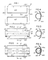
- FIGURE 1 illustrates a planar view of a sheet in accordance with the present invention prior to its being formed into a cylindrical shape.
- FIGURE 2 illustrates a front plan view of a formed retainer.
- FIGURE 3 is a plan end view of the device shown in FIGURE 2.
- FIGURE 4 is a cross-sectional view through section 4-4 of FIGURE 2.
- FIGURE 5 is a front sectional view of the device shown in FIGURE 2 and also illustrates the placement of a gas generator therein.
- FIGURE 6 is a cross-sectional view through section 6-6 of FIGURE 5.
- FIGURE 7 illustrates a planar view of another embodiment of the present invention.
- FIGURE 8 illustrates a front plan view of a retainer obtained with this alternate embodiment.
- FIGURE 9 illustrates a cross-sectional view of the invention in its fully assembled configuration.
- FIGURE 10 is an enlarged view of a portion of FIGURE 9.
- FIGURE 11 is an alternate embodiment of some of the elements of FIGURE 10.
- FIGURE 12 illustrates a projected view of an outer can.
- FIGURE 13 diagramatically illustrates an air bag usable in the present invention.
- FIGURE 14 illustrates a further embodiment of the invention.
- FIG. 1 With reference to the FIGUREs, and in particular FIGURE 1, there is shown a planar view of an integral air bag/inflater/heat shield 20, hereinafter called retainer 20 in an early stage of assembly.
- the retainer 20 comprises a substantially planar metal sheet 21 having formed therein two opposing U-shaped slots 22a and 22b. Such slots may be sharp cornered as illustrated, curved, etc. Positioned above slot 22a are a plurality of openings 24a and positioned below slot 22b are another plurality of slots 24b.
- the sets of openings 24a and b are fabricated in sides 26a and b of the sheet 21.
- the openings 24a and 24b are aligned and spaced relative to one another such that when the planar sheet 21 is rolled about itself and the sides are placed in overlapping engagement as shown in FIGUREs 2-4 the sets of holes 24a and b will be registered one to the other.
- a bolt shown diagramatically in FIGUREs 3 and 4 will extend through the registered holes 24.
- the two opposing U-shaped slots 22a and b define therebetween a center member 40 and ends 42a and b within the sheet 21.
- the distance between the holes 24a and b is chosen such that when the sheet 21 is in its rolled over configuration its diameter is slightly larger than the diameter of an associated gas generator 50 (see FIGUREs 5 and 6).
- the bolt shown in FIGURE 6 is a diagramatic representation.
- FIGURE 2 such figure illustrates a formed retainer 20, i.e., cylinder 28, with the sides 26a and b in overlapping, registered alignment.
- the ends 42a and b have been formed into cylindrical end bands 52a and b joined at a forwardly extending location by the center member 40 which forms a partially enclosed axially extending side 54 of the cylinder 28, the overlapping sides 24a and 24b forming a rear side 56 thereof.
- FIGUREs 7 and 8 illustrate an alternate embodiment of the present invention.
- the retainer 20' also is formed from planar metal sheet having formed therein plurality of sets of opposing and spaced U-shaped slots 22a-c.
- the sides 26a and b include the plurality of aligned openings 24a and b.
- the planar sheet similarly defines the ends 42 and center member 40.
- the sets of slots are axially spaced at 44 and b.
- a substantially cylindrical retainer 20' Upon rolling over the planar sheet 21', a substantially cylindrical retainer 20' is formed.
- the members 60a-f of the planar sheet 21' form a plurality of wing-like structures extending from the general cylindrical shape of the retainer 20'.
- the members 60a-f form a plurality of openings 70a-f about the periphery of the retainer 20' and the spaces 44 form middle bands 52c and d.
- FIGURE 9 illustrates a cross-sectional view of a completed assembly showing a gas generator 50 positioned within a retainer such as retainer 20.
- FIGURE 5 would also represent a cross-sectional view of the embodiment of FIGUREs 7 and 8.
- a bolt 80 having external threads 82 is received through each of the registered openings 24a and b and urges the gas generator 50 forwardly against the inner walls of the bands 52 and center member 40, i.e., side 54.
- the bolt 80 may be secured to the retainer by a threaded nut 84 shown in greater detail in FIGURE 11.
- a threaded nut 84 one for each opening such as 24a-b, is secured to the inner wall of side 26a.
- each bolt 80 will create a respective indentation 88 shown in exaggerated scale, within the wall 86 of the gas generator and to positively secure the gas generator to the retainer 20.
- the extension of the bolt 80 into the gas generator 50 secures it in a general radial compressive manner.
- the cooperation of each of the bolts 80 and their respective indentations 88 prevent the gas generator from moving laterally within the retainer 20.
- Each bolt 80 may include a slot or recess to facilitate turning.
- the openings 90 (see FIGURE 9) of the gas generator will be positioned in direct communication with the openings 62 (or 70) to permit the unimpeded transport of the gases to vacilitate an efficient expansion of an air bag 100.
- the propellant within the gas generator 50 is not shown.
- the various bands 52 provide for the primary mode of securement of the gas generator 50within the formed cylinder 28 and the front facing side 54 a secondary mode of securement.
- the front side 54 also adds a degree of structural rigidity to the cylinder 28 (retainer 20;20'). It is within the scope of the present invention that the front side 54 may be eliminated since once the gas generator 50 is in place there is no particular need for a rigid front side 54. In this situation the side 54 may be replaced by any number of bands 52 (2,3,4, etc.) forming a plurality of wing-like members (projections) 62. As an example, and with reference to FIGURE 7, the various slots 22 would extend into the middle of the sheet 21'.
- the various projections 62 could be cut to a length corresponding to that illustrated in FIGURE 17.
- such retainer would iclude the rear side 56, a plurality of bands 52 and projections extending therefrom.
- By eliminating the "side" material between the bands 52 would now expose a greater frontal area of the gas generator 50 yielding a greater option in the placement of its opening 90.
- the various wing-like members 60 of the various embodiments of the retainer 20 and 20' extend substantially tangentially outward from the rear of the rolled over retainer 20. In this configuration the various portions 60 provide a heat shield for the air bag 100 and also direct the hot gases, shown as arrows 92, forwardly into the air bag.
- the air bag 100 in FIGURE 9 is shown in its folded orientation secured to a retainer such as 20.
- a retainer such as 20.
- This air bag comprises a nylon - pillow enclosed at one end and having an open end that includes flaps 102a and 102b.
- the flaps include a plurality of registered openings 106a and 106b, see FIGUREs 9,13,14, which when in overlapping configuration about the retainer 20 are aligned to the openings 24 which are positioned about the bolt 80 so that it passes therethrough.
- the air bag is maintained in its folded orientation relative to ther retainer 20 by a band or material such as 110 received thereabout.
- the material (sack, band, etc.) 110 is chosen of a material having a tensile stress sufficient to maintain the bag 100 its pre-deployed, folded condition. The strength of the material is such that during initial deployment of the air bag 100 the deployment forces are sufficient to rupture it, thereby permitting the bag 100 to expand with negligible restriction.
- the material used may be a plastic film, cloth or spun bonded olefin material such as that manufactured under the name of TYVEK manufactured by E. I. DuPont.
- a further advantage of the present invention is that the air bag 100 and securing material 110 can be mounted to the retainer 20 prior to insertion of the gas generator. This permits the partial assembly of the retainer/air bag/securing material independent of the gas generator such that the subassembly can be stored in an environment that might be considered hostile to the gas generator.
- FIGURE 10 illustrates an enlarged view of a portion of FIGURE 9 but with an alternate means of securing the ends 26 of the sheet 21 and for supporting the bolt 80.
- the set of openings 24a are made slightly wider than the corresponding set of openings 24b.
- a clinch nut or rivet 140 having internal threads 142 is inserted within the openings 24a and b.
- the clinch nut 140 includes a clinching end 144 which when formed secures the ends 26a and b in place thereabout.
- the bolt 80 is thereafter threaded through the clinch nut 140 and into engagement with the gas generator 50.
- the planar sheet 21 is formed into a general cylindrical shape as shown in FIGURE 2. While a circular cylinder is shown other shapes are within the scope of the invention.
- the bolts 80 would be threaded into corresponding nuts 82, cinch nuts 140 etc., by a screwdriver or other means by virtue of the slot or recess 90 at the end of the bolts 80.
- the air bag 100 with its overlapping flaps 102 are placed about the retainer and the associated openings 106 fitted over each of the bolts 80 in overlapping configuration.
- the securement material 110 is then placed about the retainer 20, air bag 100 and bolts 80, forming a configuration similar to that shown in FIGURE 9 and 12.
- Such assembly may be placed within a partial shroud such as 124 or within an outer can 130 such as that shown in FIGURE 8.
- the shroud 124 or can 130 can be formed as an integral portion of the vehicle's instrument panel or as a separate element. If a partial shroud is used the retainer 20 with air bag, etc. is positioned therein with bolts 80 received in aligned openings 126. The gas generator is thereafter received within the open end 122 of the retainer 20. If a can such as 130 is used upon placement of the retainer 20, air bag 100, etc., within the can, the bolts 80 will extend through cooperating openings 134 in a rear wall thereof.
- the gas generator may then be slid through an opening 136 in a side wall 138 and into the retainer 20. Thereafter, the bolts would be moved to engage the gas generator in its secured configuration and a nut 140 positoned about each bolt 80 to secure the gas generator 50, retainer, etc. within the can 130 or shroud 124.
- the can 130 or shroud 120 may be attached to structurally sound members, shown diagramatically as 138, of the vehicle proximate the instrument panel for proper mounting of the above-described device. A portion of the instrument panel or separate cover (not shown) is placed over the air bag.
- the retainers 20 or 20' secure the gas generator 50 and provide heat shielding functions to protect and inflate the air bag.
- the shroud 124 or can 130 By attaching the retainer to the vehicle structure via the bolts 80 or other means, permits the shroud 124 or can 130 to be fabricated of an extremely light weight material such as plastic since the reaction forces generated upon ignition of the gas generator are transferred directly to the vehicle support members 138.
- the shroud 124 and/or can 130 can, of course, be themselves structural members designed to absorb a portion of the reaction force, however, in this case such elements, i.e., the shroud and can, would be fabricated of metal or the like.
- FIGURE 14 illustrates the air bag 100 in its inflated position.
- the retainer is shown schematically at 20 and is placed in a known manner within an upper top portion of the vehicle's dashboard (not shown) such that upon inflation the air bag expands and impacts a windshield 150. Thereafter, the air bag is deflected forwardly and downwardly toward the occupant.
- many air bags include tethers such as 152a and b. These tethers as is known in the art comprise reinforced material portions that are typically sewn to selected portions within the interior of the air bag 100.
- tether As an example of one type of tether used in the art, is a reinforced narrow band of material similar to seat belt webbing. This tether is typically sewn across the face 154 of the air bag at locations 156a and/or b. The tether extends toward the narrowed neck portion 158 of the air bag and had typically been sewn together at location 160.
- Another type of tether is that formed by a trapozoidal piece of material having its wider end sewn to the air bag 100 at location 156 and its narrower end, i.e., approximate the neck 158 of the air bag sewn at location 160. The process of sewing the tether at the forward location 156 of the air bag is a relatively straightforward operation.
- the process of sewing the tether at location 160 is considerably more difficult. If two tethers 152a and b are used, the sewing operation typically requires that both tethers be sewn together and to the air bag at location 160. This problem can be obviated by the present invention. It is envisioned that the tethers 152 would be sewn to the air bag at location(s) 156 in the normal manner. The tethers would as known in the art be loosely received relative to the sides of the air bag and extend toward the narrowed neck 158 of the air bag. The tethers, however, in the present invention would include an additional length of material generally shown as 162 which would be brought into engagement with the rear side of the retainer 22.
- This additional material 162 would aslo include openings 164 to permit the receipt of the bolts 80.
- the tethers can now be fixed to a permanent and definite reference point to more precisely define the trajectory of the air bag and any tether reaction loading supported by the retainer 22 as opposed to being absorbed by other portions of the air bag.
Landscapes
- Engineering & Computer Science (AREA)
- Mechanical Engineering (AREA)
- Physics & Mathematics (AREA)
- Fluid Mechanics (AREA)
- Air Bags (AREA)
Applications Claiming Priority (2)
| Application Number | Priority Date | Filing Date | Title |
|---|---|---|---|
| US401216 | 1989-08-31 | ||
| US07/401,216 US4944527A (en) | 1989-08-31 | 1989-08-31 | Integral retainer, heat shield and assembly |
Publications (2)
| Publication Number | Publication Date |
|---|---|
| EP0489754A1 EP0489754A1 (en) | 1992-06-17 |
| EP0489754B1 true EP0489754B1 (en) | 1993-08-18 |
Family
ID=23586849
Family Applications (1)
| Application Number | Title | Priority Date | Filing Date |
|---|---|---|---|
| EP90911785A Expired - Lifetime EP0489754B1 (en) | 1989-08-31 | 1990-06-26 | Integral retainer, heat shield and assembly |
Country Status (7)
| Country | Link |
|---|---|
| US (1) | US4944527A (https=) |
| EP (1) | EP0489754B1 (https=) |
| JP (1) | JPH0694269B2 (https=) |
| CA (1) | CA2012200A1 (https=) |
| DE (1) | DE69002834T2 (https=) |
| MX (1) | MX166601B (https=) |
| WO (1) | WO1991003391A1 (https=) |
Cited By (1)
| Publication number | Priority date | Publication date | Assignee | Title |
|---|---|---|---|---|
| WO2008061679A1 (de) * | 2006-11-25 | 2008-05-29 | Autoliv Development Ab | Airbaganordnung mit einem innenseitig des gassackes befestigten gasgenerator |
Families Citing this family (55)
| Publication number | Priority date | Publication date | Assignee | Title |
|---|---|---|---|---|
| US5205583A (en) * | 1990-04-04 | 1993-04-27 | Mercedes-Benz Ag | Inflatable airbag |
| US5692768A (en) * | 1991-10-21 | 1997-12-02 | Trw Vehicle Safety Systems Inc. | Airbag assembly |
| DE4137691A1 (de) * | 1991-11-15 | 1992-11-12 | Daimler Benz Ag | Gassack-einheit mit einer gasgeneratoraufnahme |
| JPH05139234A (ja) * | 1991-11-25 | 1993-06-08 | Tokai Rika Co Ltd | エアバツグケース |
| US5340147A (en) * | 1991-12-19 | 1994-08-23 | Alliedsignal Inc. | Air bag inflator assembly |
| US5332256A (en) * | 1992-02-24 | 1994-07-26 | Morton International, Inc. | Continuous circumference diffuser reaction canister |
| DE4220499C2 (de) * | 1992-06-23 | 1998-06-04 | Daimler Benz Ag | Aufprallschutzsystem mit Gassack (Airbag) |
| US5542701A (en) * | 1992-10-26 | 1996-08-06 | Alliedsignal Inc. | Wire track with integral sealing mechanism and inflator |
| US5308108A (en) * | 1992-10-26 | 1994-05-03 | Allied-Signal Inc. | Manifold or retainer for a gas generator |
| US5263739A (en) * | 1992-12-28 | 1993-11-23 | General Motors Corporation | Air bag module |
| US5398958A (en) | 1994-04-15 | 1995-03-21 | Trw Vehicle Safety Systems Inc. | Tethered attachment for an air bag |
| US5441299A (en) * | 1994-04-25 | 1995-08-15 | Morton International, Inc. | Air bag inflator subassembly for installation onto the dashboard substrate of a motor vehicle |
| US5460400A (en) * | 1994-05-20 | 1995-10-24 | Takata, Inc. | Passenger-side air bag module with improved assembly features |
| JP3017382U (ja) * | 1994-05-26 | 1995-10-24 | モートン インターナショナル,インコーポレイティド | 自動車エアバッグクッション部材用頭布状熱遮蔽具 |
| US5503429A (en) * | 1994-09-01 | 1996-04-02 | Trw Vehicle Safety Systems Inc. | Vehicle occupant restraint apparatus and method of assembly |
| US5547214A (en) * | 1995-01-23 | 1996-08-20 | Alliedsignal Inc. | Side impact soft pack air bag module |
| US5498030A (en) * | 1995-03-28 | 1996-03-12 | General Motors Corporation | Air bag module |
| US5544911A (en) * | 1995-07-05 | 1996-08-13 | Morton International, Inc. | Airbag module diffuser with flange extensions |
| US5547217A (en) * | 1995-07-06 | 1996-08-20 | Automotive Systems Laboratory, Inc. | Air bag inflator and method of manufacture thereof |
| DE19536603A1 (de) * | 1995-09-30 | 1997-04-03 | Bayerische Motoren Werke Ag | Rückhalteeinrichtung mit einem Luftsack |
| US5568936A (en) * | 1995-11-08 | 1996-10-29 | Morton International, Inc. | Airbag module case for side impact airbag module |
| JP2973912B2 (ja) * | 1996-02-09 | 1999-11-08 | トヨタ自動車株式会社 | 助手席用エアバッグ装置及びこれに適用されるバッグ折り畳み方法 |
| US5645295A (en) * | 1996-04-02 | 1997-07-08 | Trw Vehicle Safety Systems Inc. | Seat mounted air bag module |
| JP3016746B2 (ja) * | 1996-04-24 | 2000-03-06 | ペトリ・アーゲー | ガスバッグ |
| DE29608055U1 (de) * | 1996-04-24 | 1996-07-18 | Daimler Benz Ag | Gassack, insbesondere für ein Seitenairbagmodul |
| US5632506A (en) * | 1996-06-14 | 1997-05-27 | Trw Vehicle Safety Systems Inc. | Vehicle occupant protection apparatus |
| DE19626463B4 (de) * | 1996-06-21 | 2005-07-07 | Takata-Petri Ag | Vorrichtung zur Beeinflussung des Einströmens des Gases in einen Gassack eines Airbagmoduls |
| DE29612777U1 (de) * | 1996-07-23 | 1996-11-21 | Trw Repa Gmbh | Gassack-Modul für ein Fahrzeuginsassen-Rückhaltesystem |
| US5788266A (en) * | 1996-09-16 | 1998-08-04 | Autoliv Asp, Inc. | Simplified airbag module housing |
| US6095561A (en) * | 1997-03-07 | 2000-08-01 | Automotive Systems Laboratory, Inc. | Multi-chamber inflator |
| DE19710063B4 (de) * | 1997-03-12 | 2005-09-01 | Trw Automotive Safety Systems Gmbh & Co. Kg | Airbag mit Gaserzeuger |
| DE19736065C2 (de) * | 1997-08-20 | 2001-05-10 | Porsche Ag | Verfahren zum Falten eines Gassackes |
| DE19909426B4 (de) * | 1998-11-13 | 2004-12-30 | Takata-Petri Ag | Airbageinheit |
| US6422601B1 (en) | 1999-05-11 | 2002-07-23 | Automotive Systems Laboratory, Inc. | Dual chamber inflator |
| US6543803B1 (en) * | 1999-07-16 | 2003-04-08 | Ts Tech Co., Ltd. | Air bag apparatus |
| US6364341B1 (en) * | 1999-11-30 | 2002-04-02 | Breed Automotive Technology, Inc. | Air bag and module |
| US6659500B2 (en) | 2000-05-11 | 2003-12-09 | Automotive Systems Laboratory, Inc. | Multi-chamber inflator |
| US6846013B2 (en) | 2001-11-19 | 2005-01-25 | Autoliv Asp, Inc. | Airbag inflator diffuser system and method of manufacture |
| JP3922073B2 (ja) * | 2002-04-02 | 2007-05-30 | タカタ株式会社 | 外面展開型エアバッグ装置 |
| EP1497162B1 (en) * | 2002-04-19 | 2010-05-05 | Automotive Systems Laboratory Inc. | Inflator |
| EP1508486B1 (de) * | 2003-08-19 | 2009-06-17 | Delphi Technologies, Inc. | Airbagmodul |
| DE10339523B4 (de) * | 2003-08-21 | 2017-10-19 | TAKATA Aktiengesellschaft | Airbagmodul mit Gasgenerator und mit mindestens einem hülsenförmigen Massenstromverteiler |
| DE202004000801U1 (de) * | 2004-01-20 | 2004-05-27 | Trw Airbag Systems Gmbh | Vorrichtung zum Betätigen eines Fahrzeugsicherheitssystems |
| US7370884B2 (en) * | 2004-03-02 | 2008-05-13 | Autoliv Asp, Inc. | Expanding airbag inflator housing |
| DE102004038459B4 (de) * | 2004-08-07 | 2008-03-20 | Autoliv Development Ab | Airbagmodul zum Schutz eines Kraftfahrzeuginsassen |
| US7618060B2 (en) * | 2006-03-22 | 2009-11-17 | Trw Vehicle Safety Systems Inc. | Air bag module with an integral shield |
| US7731234B2 (en) * | 2007-03-06 | 2010-06-08 | Trw Vehicle Safety Systems Inc. | Air bag module with diffuser |
| FR2918583B1 (fr) * | 2007-07-13 | 2011-06-10 | Commissariat Energie Atomique | Dispositif generateur de gaz portable et alimentation electrique a pile a combustible comportant un tel dispositif |
| US8408582B2 (en) | 2010-06-23 | 2013-04-02 | Autoliv Asp, Inc. | Inflatable airbag assemblies with heat shields |
| US8820784B1 (en) * | 2010-09-23 | 2014-09-02 | Tk Holdings Inc. | Gas deflector for gas generating system |
| DE102011116447A1 (de) * | 2011-10-20 | 2013-04-25 | Gm Global Technology Operations, Llc | Sicherheitseinrichtung mit elastischer Membran |
| JP5933236B2 (ja) * | 2011-11-29 | 2016-06-08 | オートリブ ディベロップメント エービー | ガス供給装置およびエアバッグ装置 |
| US9475255B2 (en) * | 2012-08-27 | 2016-10-25 | Airbag Technologies Llc | Heat resistant coating for use in airbags and methods of their manufacture |
| DE102012019872A1 (de) * | 2012-10-10 | 2014-04-10 | Trw Airbag Systems Gmbh | Gasgeneratorbefestigung |
| HUE038268T2 (hu) * | 2013-01-03 | 2018-10-29 | Key Safety Systems Inc | Légzsákmodul hõellenzõvel |
Family Cites Families (7)
| Publication number | Priority date | Publication date | Assignee | Title |
|---|---|---|---|---|
| US3853332A (en) * | 1972-03-31 | 1974-12-10 | Specialty Prod Dev Corp | Porous diffuser for gas supply to passenger restraint |
| US4068862A (en) * | 1974-11-20 | 1978-01-17 | Nissan Motor Co., Ltd. | Safety bag inflation apparatus with extendible guard member against contact of bag with heated gas generator |
| US4153273A (en) * | 1978-04-14 | 1979-05-08 | General Motors Corporation | Occupant restraint cushion system |
| US4191392A (en) * | 1978-08-24 | 1980-03-04 | General Motors Corporation | Occupant restraint cushion system |
| US4332398A (en) * | 1980-07-11 | 1982-06-01 | General Motors Corporation | Inflatable restraint system |
| US4414902A (en) * | 1980-12-29 | 1983-11-15 | Ford Motor Company | Container for gas generating propellant |
| US4842300A (en) * | 1988-04-01 | 1989-06-27 | Trw Vehicle Safety Systems Inc. | Vehicle air bag module with internal reinforcing structure |
-
1989
- 1989-08-31 US US07/401,216 patent/US4944527A/en not_active Expired - Lifetime
-
1990
- 1990-03-14 CA CA002012200A patent/CA2012200A1/en not_active Abandoned
- 1990-06-26 WO PCT/US1990/003604 patent/WO1991003391A1/en not_active Ceased
- 1990-06-26 EP EP90911785A patent/EP0489754B1/en not_active Expired - Lifetime
- 1990-06-26 DE DE90911785T patent/DE69002834T2/de not_active Expired - Fee Related
- 1990-06-26 JP JP2-510983A patent/JPH0694269B2/ja not_active Expired - Lifetime
- 1990-07-16 MX MX021585A patent/MX166601B/es unknown
Cited By (1)
| Publication number | Priority date | Publication date | Assignee | Title |
|---|---|---|---|---|
| WO2008061679A1 (de) * | 2006-11-25 | 2008-05-29 | Autoliv Development Ab | Airbaganordnung mit einem innenseitig des gassackes befestigten gasgenerator |
Also Published As
| Publication number | Publication date |
|---|---|
| US4944527A (en) | 1990-07-31 |
| JPH0694269B1 (https=) | 1994-11-24 |
| MX166601B (es) | 1993-01-20 |
| EP0489754A1 (en) | 1992-06-17 |
| CA2012200A1 (en) | 1991-02-28 |
| WO1991003391A1 (en) | 1991-03-21 |
| DE69002834T2 (de) | 1994-04-07 |
| JPH0694269B2 (ja) | 1994-11-24 |
| DE69002834D1 (de) | 1993-09-23 |
Similar Documents
| Publication | Publication Date | Title |
|---|---|---|
| EP0489754B1 (en) | Integral retainer, heat shield and assembly | |
| JPH04503489A (ja) | エヤーバックのガス発生器取付装置 | |
| US5564739A (en) | Side impact airbag module with soft cover | |
| US5078423A (en) | Air bag with overlapping suspension strings | |
| US5407226A (en) | Inflatable restraint system reaction canister | |
| US4964654A (en) | Air bag assembly | |
| US6161865A (en) | Interlocking airbag attachment and module assembly | |
| US5470105A (en) | Diffuser device and incorporation thereof in an inflatable restraint system | |
| US5533750A (en) | Simplified inflatable restraint module | |
| US6042147A (en) | Air-bag device | |
| US5605347A (en) | Airbag module with simplified cushion attachment | |
| US6565113B2 (en) | Air bag module | |
| JP2548872B2 (ja) | エアバッグ保持用クランプ装置 | |
| EP0620140A1 (en) | Inflatable restraint system reaction canister | |
| US20010035632A1 (en) | Airbag apparatus | |
| US5443284A (en) | Air bag cushion rivetless retainer ring, axial pin method | |
| JPH08230596A (ja) | 同乗者用エアバック拘束装置 | |
| JP2002521257A (ja) | 車両用膝拘束装置 | |
| JP2501416B2 (ja) | 搭乗者制止装置におけるカバ―保持方法 | |
| US5498024A (en) | Inflatable restraint assembly | |
| US5779261A (en) | Vehicle air bag retaining arrangement | |
| JP3020086U (ja) | 膨張可能な拘束式エアバッグモジュール | |
| AU660120B2 (en) | Inflatable restraint system reaction canister | |
| EP0687601A1 (en) | Air bag module assembly | |
| US5449195A (en) | Constant diameter inflator retainer |
Legal Events
| Date | Code | Title | Description |
|---|---|---|---|
| PUAI | Public reference made under article 153(3) epc to a published international application that has entered the european phase |
Free format text: ORIGINAL CODE: 0009012 |
|
| 17P | Request for examination filed |
Effective date: 19920220 |
|
| AK | Designated contracting states |
Kind code of ref document: A1 Designated state(s): DE FR GB IT SE |
|
| 17Q | First examination report despatched |
Effective date: 19920623 |
|
| GRAA | (expected) grant |
Free format text: ORIGINAL CODE: 0009210 |
|
| AK | Designated contracting states |
Kind code of ref document: B1 Designated state(s): DE FR GB IT SE |
|
| ITF | It: translation for a ep patent filed | ||
| REF | Corresponds to: |
Ref document number: 69002834 Country of ref document: DE Date of ref document: 19930923 |
|
| ET | Fr: translation filed | ||
| PLBE | No opposition filed within time limit |
Free format text: ORIGINAL CODE: 0009261 |
|
| STAA | Information on the status of an ep patent application or granted ep patent |
Free format text: STATUS: NO OPPOSITION FILED WITHIN TIME LIMIT |
|
| 26N | No opposition filed | ||
| EAL | Se: european patent in force in sweden |
Ref document number: 90911785.5 |
|
| PGFP | Annual fee paid to national office [announced via postgrant information from national office to epo] |
Ref country code: GB Payment date: 19960509 Year of fee payment: 7 |
|
| PGFP | Annual fee paid to national office [announced via postgrant information from national office to epo] |
Ref country code: SE Payment date: 19960517 Year of fee payment: 7 |
|
| PGFP | Annual fee paid to national office [announced via postgrant information from national office to epo] |
Ref country code: FR Payment date: 19960607 Year of fee payment: 7 |
|
| PGFP | Annual fee paid to national office [announced via postgrant information from national office to epo] |
Ref country code: DE Payment date: 19960625 Year of fee payment: 7 |
|
| PG25 | Lapsed in a contracting state [announced via postgrant information from national office to epo] |
Ref country code: GB Free format text: LAPSE BECAUSE OF NON-PAYMENT OF DUE FEES Effective date: 19970626 |
|
| PG25 | Lapsed in a contracting state [announced via postgrant information from national office to epo] |
Ref country code: SE Effective date: 19970627 |
|
| GBPC | Gb: european patent ceased through non-payment of renewal fee |
Effective date: 19970626 |
|
| PG25 | Lapsed in a contracting state [announced via postgrant information from national office to epo] |
Ref country code: FR Free format text: LAPSE BECAUSE OF NON-PAYMENT OF DUE FEES Effective date: 19980227 |
|
| EUG | Se: european patent has lapsed |
Ref document number: 90911785.5 |
|
| PG25 | Lapsed in a contracting state [announced via postgrant information from national office to epo] |
Ref country code: DE Free format text: LAPSE BECAUSE OF NON-PAYMENT OF DUE FEES Effective date: 19980303 |
|
| REG | Reference to a national code |
Ref country code: FR Ref legal event code: ST |
|
| REG | Reference to a national code |
Ref country code: FR Ref legal event code: ST |
|
| PG25 | Lapsed in a contracting state [announced via postgrant information from national office to epo] |
Ref country code: IT Free format text: LAPSE BECAUSE OF NON-PAYMENT OF DUE FEES;WARNING: LAPSES OF ITALIAN PATENTS WITH EFFECTIVE DATE BEFORE 2007 MAY HAVE OCCURRED AT ANY TIME BEFORE 2007. THE CORRECT EFFECTIVE DATE MAY BE DIFFERENT FROM THE ONE RECORDED. Effective date: 20050626 |