EP0489226A1 - Verfahren und Vorrichtung zum Verbessern des Bettmasse-Ausbrandes bei Wirbelschichtfeuerungen - Google Patents
Verfahren und Vorrichtung zum Verbessern des Bettmasse-Ausbrandes bei Wirbelschichtfeuerungen Download PDFInfo
- Publication number
- EP0489226A1 EP0489226A1 EP91110461A EP91110461A EP0489226A1 EP 0489226 A1 EP0489226 A1 EP 0489226A1 EP 91110461 A EP91110461 A EP 91110461A EP 91110461 A EP91110461 A EP 91110461A EP 0489226 A1 EP0489226 A1 EP 0489226A1
- Authority
- EP
- European Patent Office
- Prior art keywords
- melting chamber
- bed
- fluidized bed
- chamber
- dust
- Prior art date
- Legal status (The legal status is an assumption and is not a legal conclusion. Google has not performed a legal analysis and makes no representation as to the accuracy of the status listed.)
- Withdrawn
Links
Images
Classifications
-
- F—MECHANICAL ENGINEERING; LIGHTING; HEATING; WEAPONS; BLASTING
- F23—COMBUSTION APPARATUS; COMBUSTION PROCESSES
- F23C—METHODS OR APPARATUS FOR COMBUSTION USING FLUID FUEL OR SOLID FUEL SUSPENDED IN A CARRIER GAS OR AIR
- F23C10/00—Fluidised bed combustion apparatus
- F23C10/02—Fluidised bed combustion apparatus with means specially adapted for achieving or promoting a circulating movement of particles within the bed or for a recirculation of particles entrained from the bed
- F23C10/04—Fluidised bed combustion apparatus with means specially adapted for achieving or promoting a circulating movement of particles within the bed or for a recirculation of particles entrained from the bed the particles being circulated to a section, e.g. a heat-exchange section or a return duct, at least partially shielded from the combustion zone, before being reintroduced into the combustion zone
- F23C10/08—Fluidised bed combustion apparatus with means specially adapted for achieving or promoting a circulating movement of particles within the bed or for a recirculation of particles entrained from the bed the particles being circulated to a section, e.g. a heat-exchange section or a return duct, at least partially shielded from the combustion zone, before being reintroduced into the combustion zone characterised by the arrangement of separation apparatus, e.g. cyclones, for separating particles from the flue gases
- F23C10/10—Fluidised bed combustion apparatus with means specially adapted for achieving or promoting a circulating movement of particles within the bed or for a recirculation of particles entrained from the bed the particles being circulated to a section, e.g. a heat-exchange section or a return duct, at least partially shielded from the combustion zone, before being reintroduced into the combustion zone characterised by the arrangement of separation apparatus, e.g. cyclones, for separating particles from the flue gases the separation apparatus being located outside the combustion chamber
-
- F—MECHANICAL ENGINEERING; LIGHTING; HEATING; WEAPONS; BLASTING
- F27—FURNACES; KILNS; OVENS; RETORTS
- F27B—FURNACES, KILNS, OVENS, OR RETORTS IN GENERAL; OPEN SINTERING OR LIKE APPARATUS
- F27B15/00—Fluidised-bed furnaces; Other furnaces using or treating finely-divided materials in dispersion
- F27B15/02—Details, accessories, or equipment peculiar to furnaces of these types
- F27B15/12—Arrangements of dust collectors
-
- F—MECHANICAL ENGINEERING; LIGHTING; HEATING; WEAPONS; BLASTING
- F23—COMBUSTION APPARATUS; COMBUSTION PROCESSES
- F23C—METHODS OR APPARATUS FOR COMBUSTION USING FLUID FUEL OR SOLID FUEL SUSPENDED IN A CARRIER GAS OR AIR
- F23C2206/00—Fluidised bed combustion
- F23C2206/10—Circulating fluidised bed
- F23C2206/101—Entrained or fast fluidised bed
-
- F—MECHANICAL ENGINEERING; LIGHTING; HEATING; WEAPONS; BLASTING
- F23—COMBUSTION APPARATUS; COMBUSTION PROCESSES
- F23G—CREMATION FURNACES; CONSUMING WASTE PRODUCTS BY COMBUSTION
- F23G2202/00—Combustion
- F23G2202/20—Combustion to temperatures melting waste
-
- F—MECHANICAL ENGINEERING; LIGHTING; HEATING; WEAPONS; BLASTING
- F23—COMBUSTION APPARATUS; COMBUSTION PROCESSES
- F23G—CREMATION FURNACES; CONSUMING WASTE PRODUCTS BY COMBUSTION
- F23G2204/00—Supplementary heating arrangements
- F23G2204/10—Supplementary heating arrangements using auxiliary fuel
-
- F—MECHANICAL ENGINEERING; LIGHTING; HEATING; WEAPONS; BLASTING
- F23—COMBUSTION APPARATUS; COMBUSTION PROCESSES
- F23G—CREMATION FURNACES; CONSUMING WASTE PRODUCTS BY COMBUSTION
- F23G2209/00—Specific waste
- F23G2209/30—Solid combustion residues, e.g. bottom or flyash
Definitions
- the invention relates to a method and a device for improving the bed mass burnout in furnaces with a circulating fluidized bed.
- the invention has for its object to provide a method and an apparatus for improving the burnout of the bed mass, which work properly without excessive increase in the recycle ratio, result in solids that can be used in industry or landfill and avoid an increase in the pollutant content of the flue gases.
- the solution to this problem is that in the method mentioned at the beginning, at least part of the flying dust is drawn off according to the invention and fed to at least one furnace furnace.
- the combustible solids of the extracted dust are practically completely burned in the melting chamber firing at high temperature, while the solid (ash) can be drawn off as molten slag and granulated in a wet deslagger.
- the extracted dust can be burned in the melting chamber with the addition of air, preferably preheated air and / or an additional fuel.
- air preferably preheated air and / or an additional fuel.
- the additional fuel can consist of coal dust, fuel gas or heating oil.
- the flue gases from the melting chamber firing can be fed to the fluidized bed firing in a zone with a lack of oxygen.
- the NO X arising in the melting chamber due to the high temperature is then largely reduced to nitrogen and oxygen or CO2 in this zone.
- the SO2 formed during combustion in the melting chamber from the fuel sulfur and the gypsum disintegration and the SO2 from the fuel sulfur of the fluidized bed furnace are bound to the lime or dolomite added to the fluidized bed. This means that there are no other emission products than normal low-temperature combustion in a circulating fluidized bed; Heavy metals contained in the flying dust are incorporated into the liquid slag in the melting chambers.
- the device according to the invention is designed in such a way that at least part of the flying dust is fed to at least one burner in at least one melting chamber, which is preferably a ceiling burner.
- the melting chamber can be connected to a vortex combustion chamber via nozzles or to the wind box under the nozzle floor of the vortex combustion chamber and preferably open into a zone with a lack of oxygen.
- a zone with a lack of oxygen can be located in the lower part of the vortex combustion chamber, so that it is ultimately Excess oxygen required for the burnout only results in the area of the supply of secondary air in the upper area of the swirl combustion chamber.
- a start-up burner can be arranged in the melting chamber, which can be operated with coal dust, fuel gas or heating oil.
- the fluidized bed reactor for the fluidized bed combustion can have a rectangular cross section in the usual way, the lower region of which is tapered. At least one immersion pot, at least one fluid bed cooler for bed mass returned via at least one cyclone separator and at least one melting chamber can then be arranged laterally next to this lower part.
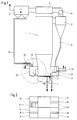
- a vortex combustion chamber 1 can be operated from a large steam generator with fluidized bed combustion, not shown in detail have cooled walls and / or cooling internals.
- the separated bed mass passes through a chute 3 into at least one immersion pot or siphon 8.
- the flue gases and entrained flue dust pass from the return cyclone 2 via a train 4 to secondary heating surfaces 5 and are fed from there via a filter or deduster 6 to a chimney (not shown).
- a bed ash extractor 7 is located on the tapered lower part 11 of the vortex combustion chamber 1.
- the primary air for the vortex combustion chamber 1 is distributed in a wind box 22, which is preferably cooled by tube walls.
- Part of the bed mass fed to the immersion pot 8 is fed to a fluidized bed cooler 9 by means of a control valve 10.
- the bed mass of the immersion pot 8 and the fluidized bed cooler 9 is partly returned to the lower part 11 of the vortex combustion chamber 1 and partly withdrawn.
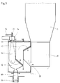
- a melting chamber 12 is arranged in the area of the lower part 11, the immersion pot 8 and the fluidized bed cooler 9.
- a ceiling burner 13 with an air supply 14 and a flight dust supply 15.
- a start-up burner 21 is arranged in the center of the main burner and serves to set an ignition temperature which is so high that the combustible solid components are in a stable flame 16 burn.
- the flight dust supply 15 is connected to the deduster 6.
- the flight dust supply 15 can also be supplied with other solids, for example from the bed ash extractor 7, the immersion pots 8 and the fluid bed cooler 9. Likewise, if the capacity of the melting chamber 12 is sufficient, use further solids, for example ashes from other coal dust furnaces.
- the ceiling burner 13 is set, if necessary by supplying additional fuel in the form of coal dust, heating oil or fuel gas in conjunction with preheated air, so that a flame 16 is formed, the combustion temperature of which is so high that the solids melt and melt as liquid slag into a liquid slag extractor 18 reach. There they are granulated in a wet deslagger 19 and taken to downstream settling and transport devices, not shown.
- the melting chamber 12 consists of radiation chambers 17 and the flue gases are guided through these radiation chambers 17 to nozzles 20 which open into the lower part 11 of the vortex combustion chamber 1.
- This lower part 11 forms a zone with a lack of oxygen or reducing conditions, so that the NO x formed at the high combustion temperatures of the melting chamber 12 is largely reduced.
- the SO 2 formed during the combustion passes with the flue gases from the melting chamber 12 via the nozzles 20 into the lower part 11 of the vortex combustion chamber 1 it with the lime or dolomite usually supplied to the vortex combustion chamber 1 and is set in this way.
- there is a different need for lime depending on the degree of primary incorporation of the gypsum that is removed from the swirl combustion chamber during desulphurization, there is a different need for lime.
- start-up burner 21 which can be operated with lignite dust, heating oil or fuel gas.
- the granulated slag from the melting chamber 12 is practically free of unburned and elutable constituents and can be treated or reused in the same way as the slag of a large steam generator with conventional smelting chamber firing, but without the pollutants which are inevitably formed in a conventional smelting furnace being emitted with the flue gas and by downstream desulphurization and denitrification plants must be disposed of.
Landscapes
- Engineering & Computer Science (AREA)
- Chemical & Material Sciences (AREA)
- Mechanical Engineering (AREA)
- General Engineering & Computer Science (AREA)
- Dispersion Chemistry (AREA)
- Combustion & Propulsion (AREA)
- Fluidized-Bed Combustion And Resonant Combustion (AREA)
- Gasification And Melting Of Waste (AREA)
Applications Claiming Priority (2)
| Application Number | Priority Date | Filing Date | Title |
|---|---|---|---|
| DE19904038878 DE4038878C1 (ja) | 1990-12-06 | 1990-12-06 | |
| DE4038878 | 1990-12-06 |
Publications (1)
| Publication Number | Publication Date |
|---|---|
| EP0489226A1 true EP0489226A1 (de) | 1992-06-10 |
Family
ID=6419694
Family Applications (1)
| Application Number | Title | Priority Date | Filing Date |
|---|---|---|---|
| EP91110461A Withdrawn EP0489226A1 (de) | 1990-12-06 | 1991-06-25 | Verfahren und Vorrichtung zum Verbessern des Bettmasse-Ausbrandes bei Wirbelschichtfeuerungen |
Country Status (2)
| Country | Link |
|---|---|
| EP (1) | EP0489226A1 (ja) |
| DE (1) | DE4038878C1 (ja) |
Cited By (3)
| Publication number | Priority date | Publication date | Assignee | Title |
|---|---|---|---|---|
| DE4403634A1 (de) * | 1994-02-05 | 1995-08-10 | Heinen Maschf Gmbh | Filter zum Zurückhalten von Partikeln |
| CN103267415A (zh) * | 2013-06-07 | 2013-08-28 | 瓮福(集团)有限责任公司 | 一种硫铁矿制酸生产中焙烧炉铺渣方法 |
| WO2017092876A1 (de) * | 2015-12-04 | 2017-06-08 | Wincip Gmbh | Verfahren und anlage zur erzeugung eines vergasungsmittels für einen vergasungsprozess |
Citations (4)
| Publication number | Priority date | Publication date | Assignee | Title |
|---|---|---|---|---|
| US2803530A (en) * | 1952-05-28 | 1957-08-20 | Texaco Development Corp | Process for the production of carbon monoxide from a solid fuel |
| FR2556983A1 (fr) * | 1983-12-23 | 1985-06-28 | Creusot Loire | Procede et installation de traitement de matieres en lit fluidise, en particulier pour la combustion ou gazeification de matiere combustible |
| US4696678A (en) * | 1981-03-06 | 1987-09-29 | Agency Of Industrial Science And Technology | Method and equipment for gasification of coal |
| EP0384454A2 (en) * | 1989-02-22 | 1990-08-29 | A. Ahlstrom Corporation | Apparatus for gasifying or combusting solid carbonaceous material |
Family Cites Families (1)
| Publication number | Priority date | Publication date | Assignee | Title |
|---|---|---|---|---|
| DE3520058A1 (de) * | 1985-06-04 | 1986-12-04 | O & K Orenstein & Koppel Ag, 1000 Berlin | Verfahren zur waermebehandlung von feinkoernigem gut |
-
1990
- 1990-12-06 DE DE19904038878 patent/DE4038878C1/de not_active Expired - Lifetime
-
1991
- 1991-06-25 EP EP91110461A patent/EP0489226A1/de not_active Withdrawn
Patent Citations (4)
| Publication number | Priority date | Publication date | Assignee | Title |
|---|---|---|---|---|
| US2803530A (en) * | 1952-05-28 | 1957-08-20 | Texaco Development Corp | Process for the production of carbon monoxide from a solid fuel |
| US4696678A (en) * | 1981-03-06 | 1987-09-29 | Agency Of Industrial Science And Technology | Method and equipment for gasification of coal |
| FR2556983A1 (fr) * | 1983-12-23 | 1985-06-28 | Creusot Loire | Procede et installation de traitement de matieres en lit fluidise, en particulier pour la combustion ou gazeification de matiere combustible |
| EP0384454A2 (en) * | 1989-02-22 | 1990-08-29 | A. Ahlstrom Corporation | Apparatus for gasifying or combusting solid carbonaceous material |
Cited By (3)
| Publication number | Priority date | Publication date | Assignee | Title |
|---|---|---|---|---|
| DE4403634A1 (de) * | 1994-02-05 | 1995-08-10 | Heinen Maschf Gmbh | Filter zum Zurückhalten von Partikeln |
| CN103267415A (zh) * | 2013-06-07 | 2013-08-28 | 瓮福(集团)有限责任公司 | 一种硫铁矿制酸生产中焙烧炉铺渣方法 |
| WO2017092876A1 (de) * | 2015-12-04 | 2017-06-08 | Wincip Gmbh | Verfahren und anlage zur erzeugung eines vergasungsmittels für einen vergasungsprozess |
Also Published As
| Publication number | Publication date |
|---|---|
| DE4038878C1 (ja) | 1992-03-05 |
Similar Documents
| Publication | Publication Date | Title |
|---|---|---|
| EP0118931B1 (de) | Verfahren zur Nachverbrennung und Reinigung von Prozessabgasen | |
| DE2539546C3 (de) | Verfahren zur Verbrennung kohlenstoffhaltiger Materialien | |
| DE2624302A1 (de) | Verfahren zur durchfuehrung exothermer prozesse | |
| NO153746B (no) | Fremgangsmaate til aa nedsette innholdet av nitrogenoksyder til et oensket nivaa og minimere svoveldioksydinnholdet i reaksjonsgassene fra forbrenning av brennstoff i et flerfaststoffvirvelsjikt | |
| EP0174676A1 (de) | Verfahren zur thermischen Behandlung von stückigen oder agglomerierten Materialien auf einem Wanderrost | |
| EP0302910B1 (de) | Verbrennung von kohle mit einer wirbelschichtfeuerung | |
| DE19806823C2 (de) | Vorrichtung und Verfahren zur Verbrennung vanadiumhaltiger Brennstoffe | |
| DE19722070C2 (de) | Verfahren zur NO¶x¶-armen Verbrennung von Steinkohle bei trockenentaschten Dampferzeugern | |
| DE4038878C1 (ja) | ||
| EP0278262B1 (de) | Wirbelschichtofen zur Müllverbrennung | |
| DE3623177A1 (de) | Brennkammer fuer atmosphaerische stationaere wirbelschichtfeuerung | |
| DE3324411C2 (ja) | ||
| EP0381946A1 (de) | Müllverbrennungsanlage und Verfahren zu Ihrem Betrieb | |
| EP0301714A2 (en) | Sulfur removal by sorbent injection in secondary combustion zones | |
| DE3900977C2 (ja) | ||
| DE3608248C1 (en) | Method of generating hot gas and hot-gas generator for implementing the method | |
| EP0363812A2 (de) | Verfahren und Anlage zur Dampferzeugung, insbesondere in Heizkraftwerken | |
| EP0501944B1 (de) | Verfahren und Vorrichtung zum Verbrennen von stückigen, biogenen Brennstoffen | |
| DE3818006C2 (ja) | ||
| EP0089075B1 (de) | Verfahren zur Nachverbrennung von brennbaren Bestandteilen in Abgasen von Drehrohröfen | |
| EP0146571A1 (de) | Wirbelbettfeuerungsanlage. | |
| EP0289932A1 (de) | Verfahren und Feuerungsanlage zum Verbrennen von festen fluidisierten Brennstoffen | |
| AT109020B (de) | Einrichtung und Verfahren zur Verbrennung, Vergasung der Entgasung von feinkörnigen, festen oder zerstäubten, flüssigen Brennstoffen. | |
| DE3545464A1 (de) | Verfahren zur entschwefelung von gasen, welche aus einer feuerstelle entweichen, wo die verbrennung mit agglomerieren der asche erfolgt, und anlage zur durchfuehrung dieses verfahrens | |
| DE3334686A1 (de) | Verfahren und vorrichtung zur thermischen behandlung von grobkoernigen und/oder stueckigen materialien |
Legal Events
| Date | Code | Title | Description |
|---|---|---|---|
| PUAI | Public reference made under article 153(3) epc to a published international application that has entered the european phase |
Free format text: ORIGINAL CODE: 0009012 |
|
| AK | Designated contracting states |
Kind code of ref document: A1 Designated state(s): AT BE FR GB IT NL SE |
|
| RAP1 | Party data changed (applicant data changed or rights of an application transferred) |
Owner name: LENTJES AG |
|
| STAA | Information on the status of an ep patent application or granted ep patent |
Free format text: STATUS: THE APPLICATION HAS BEEN WITHDRAWN |
|
| 18W | Application withdrawn |
Withdrawal date: 19921211 |
|
| R18W | Application withdrawn (corrected) |
Effective date: 19921211 |