EP0489188B1 - Werkzeug zum Machen und Drehen der Gewindeverbindung von Ausbruchschiebern - Google Patents
Werkzeug zum Machen und Drehen der Gewindeverbindung von Ausbruchschiebern Download PDFInfo
- Publication number
- EP0489188B1 EP0489188B1 EP90123286A EP90123286A EP0489188B1 EP 0489188 B1 EP0489188 B1 EP 0489188B1 EP 90123286 A EP90123286 A EP 90123286A EP 90123286 A EP90123286 A EP 90123286A EP 0489188 B1 EP0489188 B1 EP 0489188B1
- Authority
- EP
- European Patent Office
- Prior art keywords
- winch
- safety plug
- supporting arm
- safety
- guide
- Prior art date
- Legal status (The legal status is an assumption and is not a legal conclusion. Google has not performed a legal analysis and makes no representation as to the accuracy of the status listed.)
- Expired - Lifetime
Links
- 230000008878 coupling Effects 0.000 claims description 13
- 238000010168 coupling process Methods 0.000 claims description 13
- 238000005859 coupling reaction Methods 0.000 claims description 13
- 230000003014 reinforcing effect Effects 0.000 claims 1
- 230000000903 blocking effect Effects 0.000 description 5
- 238000005553 drilling Methods 0.000 description 2
- 230000002787 reinforcement Effects 0.000 description 2
- 125000006850 spacer group Chemical group 0.000 description 2
- 238000004873 anchoring Methods 0.000 description 1
- 230000006835 compression Effects 0.000 description 1
- 238000007906 compression Methods 0.000 description 1
- 230000001419 dependent effect Effects 0.000 description 1
- 239000011150 reinforced concrete Substances 0.000 description 1
- 238000003466 welding Methods 0.000 description 1
Images

Classifications
-
- E—FIXED CONSTRUCTIONS
- E21—EARTH OR ROCK DRILLING; MINING
- E21B—EARTH OR ROCK DRILLING; OBTAINING OIL, GAS, WATER, SOLUBLE OR MELTABLE MATERIALS OR A SLURRY OF MINERALS FROM WELLS
- E21B33/00—Sealing or packing boreholes or wells
- E21B33/02—Surface sealing or packing
- E21B33/03—Well heads; Setting-up thereof
- E21B33/06—Blow-out preventers, i.e. apparatus closing around a drill pipe, e.g. annular blow-out preventers
-
- E—FIXED CONSTRUCTIONS
- E21—EARTH OR ROCK DRILLING; MINING
- E21B—EARTH OR ROCK DRILLING; OBTAINING OIL, GAS, WATER, SOLUBLE OR MELTABLE MATERIALS OR A SLURRY OF MINERALS FROM WELLS
- E21B19/00—Handling rods, casings, tubes or the like outside the borehole, e.g. in the derrick; Apparatus for feeding the rods or cables
- E21B19/16—Connecting or disconnecting pipe couplings or joints
Definitions
- the invention relates to a device for unlocking and blocking annular safety shutters (B.O.P.) for wellbore.
- Document US-A-4 398 598 describes a device for loosening an annular shutter comprising a frame connectable to the shutter and two jacks linked in an articulated manner on the one hand to an upper plate capable of being fixed on the head of the shutter and on the other hand to the frame so that the actuation of the cylinders biases the head of the shutter.
- the device is not designed for a tightening operation
- the object of the invention is to create a device for loosening and tightening well shutter blocks guaranteeing maximum work safety and at the same time allowing significant time savings.
- the invention relates to a device according to claim 1 appended.
- the jacks are arranged essentially parallel to the jack-carrying arm and linked to the latter in an articulated manner by hinges;
- the base plate can be secured to a platform carrying a connector for the central guide; on its underside, the base plate can be provided with support legs and a stiffening frame.
- the device according to the invention allows a significant reduction in the working time necessary for loosening or tightening the well shutter block. At the same time, the risk of accident and damage to the equipment used is reduced.
- Another advantage of the invention resides in the fact that it is no longer necessary to assemble on site the loosening device and tightening of the well shutter block, but that it is transportable and can be mounted for example on another borehole sleeve.
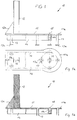
- the seat frame 10 shown in FIGS. 1, 1a and 1b is composed of a base plate 11 secured to a platform 11a.
- the base plate 11 is reinforced, on its underside, by a stiffening frame 14 and provided with support legs 13. With a view to increasing the bearing surface of the support legs 13, these are provided, at their free ends, of support plates 13a.
- a male slide 12 is arranged in a substantially vertical manner.
- the slide 12 consists of a double T profile held in position by a lateral spacer 12a.
- the platform 11a secured to the base plate 11 is substantially circular in shape and provided, in the center, with a connector 15.
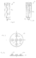
- the connector 15 is provided with a thread 15a into which the tubular central guide shown in detail in Figures 2 and 2a can be screwed.
- the guide 16 comprises an envelope 16a enclosing an inner tube 17.
- the free lower end of the inner tube 17 is provided with a male thread 17a capable of cooperating with the female thread 15a of the connector 15.
- the upper plate 19 ( Figures 3, 3a) is provided with a central coupling bore 21. Reservations 20 are provided concentrically with the central coupling bore 21, these housing bores being reinforced by reinforcement flanges 20a.
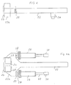
- a guide pin 26, integral with a jack-carrying arm 22 shown in Figures 4 and 4a can be introduced to cooperate with said bore.
- the arm 22 has a longitudinal extent covering almost the total length of the base plate 11, up to the area of the platform 11a and forms with the slide 12 a bracket.
- the guide pin 26 is fixed at a free end of the arm 22 to the underside of the latter.
- the free end of the arm 22 opposite the guide pin 26 is provided with a head element 22a in which is provided a female slide 24 covered by a slide flange 23.
- the female slide 24 is also formed in double T.
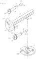
- connection eyelets 27 are provided, as shown in FIG. 5, with hinge articulation bores 34a corresponding to the hinge articulation bores 34 in the connection eyelets.
- the jacks 29 are provided with connecting rods 32 provided at their free ends with jack heads 30. At their lower faces, these jack heads 30 are provided with shoes 35 which can be brought into action relationship with the reservations 20 in the upper plate 19.
- the operation of the device which has just been described is indicated in the following: to block or unblock a safety shutter, the shutter is fixed on the base plate 11 comprising the slide 12, on which is positioned at the desired height the arm 22 by its slide 24. The height is chosen according to the height of the well shutter block 16 to be introduced.
- the upper plate 19 On the shutter, the upper plate 19 is placed, which by means of coupling fittings is fixed to the shutter.
- the guide pin 26 provided on the underside of the arm 22 engages in the central bore 21 of the upper plate 19 of which it guarantees the concentricity.
- the hydraulic drive jacks 29 arranged parallel to the arm 22 engage, with their shoes 35, in the reservations 20 of the plate 19. By means of opposite forces deployed by the jacks 29 and acting one in traction, l 'other in compression, the plate 19 and, with it the well shutter can be rotated by about half a turn, so as to loosen or tighten it.
- the cylinders 29 can follow the pivoting movement of the plate 19 and of the reservations 20 in the latter.
- the shutter can be loosened or tightened without endangering the personnel performing the operation.
Landscapes
- Engineering & Computer Science (AREA)
- Geology (AREA)
- Life Sciences & Earth Sciences (AREA)
- Mining & Mineral Resources (AREA)
- Physics & Mathematics (AREA)
- Environmental & Geological Engineering (AREA)
- Fluid Mechanics (AREA)
- General Life Sciences & Earth Sciences (AREA)
- Geochemistry & Mineralogy (AREA)
- Mechanical Engineering (AREA)
- Earth Drilling (AREA)
- Pivots And Pivotal Connections (AREA)
- Bridges Or Land Bridges (AREA)
- Multiple-Way Valves (AREA)
Claims (8)
- Vorrichtung zu Festziehen und Lösen von ringförmigen Bohrloch-Sicherungsstopfen, gekennzeichnet durch einen Bodenflansch (11) als Trägerfundament für den Sicherungsstopfen (16), eine Aufnahmeschiene (12), einen sich der Aufnahmeschiene entlang bewegender Windenträgerarm (22), der in den unterschiedlichen Höhen des Sicherungsstopfens (16) entsprechend, in der passenden Höhe an der Aufnahmeschiene feststellbar ist, eine obere Betätigungsscheibe (19), die an das obere Ende des genannten Sicherungsstopfens (16) anbringbar ist, ein am Bodenflansch (11) zubefestigendes, zur Aufnahmeschiene (12) in etwa Parallelstellung und in Abstand stehendes abnehmbares röhrenförmiges zentrisches Führungsstück (16), und durch zwei Winden (29), die einerseits an dem genannten Windenträgerarm (22) angelenkt sind und andererseits in Einsatzstellung zur oberen Betätigungsscheibe (19) stehen und die mittels Kuppelungsdornen (35) in Wirkverbindung mit Kupplungsbohrungen (20) stehen und die an der genannten oberen Betätigungsscheibe (19) so angebracht sind, daß die Betätigung der genannten Winden (29) die Tordierung des vorderen Teils des Sicherungsstopfens (16) unterstützt.
- Vorrichtung nach Anspruch 1, dadurch gekennzeichnet, daß die Winden (29) im wesentlichen parallel zum Windenträgerarm (22) stehen und mit mittels Windenanschlüssen (27, 28) an diesem angelenkt sind.
- Vorrichtung nach den Ansprüchen 1 und 2, dadurch gekennzeichnet, daß der Bodenflansch (11) einstückig mit einer Sicherungsplattform (11a) zur Festlegung des Sicherungsstopfens (16) verbunden und an seiner Unterseite mit Stützbeinen (13) und einem Versteifungsrahmen (14) versehen ist.
- Vorrichtung nach den Ansprüchen 1 bis 3, dadurch gekennzeichnet, daß der Windenträgerarm (22) mit einem Kopfstück (22a) versehen ist, und daß dieses Kopfstück (22a) einen Führungsschlitz (24) aufweist, welcher in Wirkverbindung mit Führungsbacken (25) des genannten Arms (22) auf der Aufnahmeschiene (12) steht und in eine passend feststellbare Höhe bringbar ist.
- Vorrichtung nach den Ansprüchen 2 bis 4, dadurch gekennzeichnet, daß die Windenanschlüsse (28) mit Anschlußösen (27) versehen sind, die dem Kopfstück (22a) des Windenträgerarms (22) zugeordnet sind.
- Vorrichtung nach den Ansprüchen 1 bis 5, dadurch gekennzeichnet, daß die obere Betätigungsscheibe (19) eine zentrische Kuppelungsbohrung (21) aufweist, die in Wirkverbindung mit einem am Ende des Windenträgerarms (22) vorgesehenen Führungsdorn (26) bringbar ist.
- Vorrichtung nach den Ansprüchen 3 bis 6, dadurch gekennzeichnet, daß der Sicherungsstopfen (16) ein mit einem Außengewinde (17a) versehenes Innenrohr (17) aufweist, welches mit dem Innengewinde (15a) eines Preventeranschlusses (15) korrespondiert, der sich auf der Sicherungsplattform (11a) des Bodenflansches (11) befindet.
- Vorrichtung nach dem Anspruch 7, dadurch gekennzeichnet, daß der Führungsdorn (26) paßgenau mit dem Innenrohr (17) des zentrischen Sicherungsstopfens (16) ausgebildet ist.
Priority Applications (3)
| Application Number | Priority Date | Filing Date | Title |
|---|---|---|---|
| AT90123286T ATE108510T1 (de) | 1990-12-05 | 1990-12-05 | Werkzeug zum machen und drehen der gewindeverbindung von ausbruchschiebern. |
| EP90123286A EP0489188B1 (de) | 1990-12-05 | 1990-12-05 | Werkzeug zum Machen und Drehen der Gewindeverbindung von Ausbruchschiebern |
| DE69010689T DE69010689D1 (de) | 1990-12-05 | 1990-12-05 | Werkzeug zum Machen und Drehen der Gewindeverbindung von Ausbruchschiebern. |
Applications Claiming Priority (1)
| Application Number | Priority Date | Filing Date | Title |
|---|---|---|---|
| EP90123286A EP0489188B1 (de) | 1990-12-05 | 1990-12-05 | Werkzeug zum Machen und Drehen der Gewindeverbindung von Ausbruchschiebern |
Publications (2)
| Publication Number | Publication Date |
|---|---|
| EP0489188A1 EP0489188A1 (de) | 1992-06-10 |
| EP0489188B1 true EP0489188B1 (de) | 1994-07-13 |
Family
ID=8204793
Family Applications (1)
| Application Number | Title | Priority Date | Filing Date |
|---|---|---|---|
| EP90123286A Expired - Lifetime EP0489188B1 (de) | 1990-12-05 | 1990-12-05 | Werkzeug zum Machen und Drehen der Gewindeverbindung von Ausbruchschiebern |
Country Status (3)
| Country | Link |
|---|---|
| EP (1) | EP0489188B1 (de) |
| AT (1) | ATE108510T1 (de) |
| DE (1) | DE69010689D1 (de) |
Families Citing this family (1)
| Publication number | Priority date | Publication date | Assignee | Title |
|---|---|---|---|---|
| CN111119782B (zh) * | 2020-02-27 | 2025-03-14 | 盐城市东荣石油机械有限公司 | 一种防喷盒 |
Family Cites Families (1)
| Publication number | Priority date | Publication date | Assignee | Title |
|---|---|---|---|---|
| US4398598A (en) * | 1981-05-18 | 1983-08-16 | Fabrygel Joe H | Break-out tool for annular type blow-out preventers |
-
1990
- 1990-12-05 DE DE69010689T patent/DE69010689D1/de not_active Expired - Lifetime
- 1990-12-05 AT AT90123286T patent/ATE108510T1/de not_active IP Right Cessation
- 1990-12-05 EP EP90123286A patent/EP0489188B1/de not_active Expired - Lifetime
Also Published As
| Publication number | Publication date |
|---|---|
| ATE108510T1 (de) | 1994-07-15 |
| DE69010689D1 (de) | 1994-08-18 |
| EP0489188A1 (de) | 1992-06-10 |
Similar Documents
| Publication | Publication Date | Title |
|---|---|---|
| CA2503760C (en) | Support system for power tong assembly | |
| US6907934B2 (en) | Universal top-drive wireline entry system bracket and method | |
| FR2531479A1 (fr) | Forage de puits avec unite de commande au sommet | |
| US6138776A (en) | Power tongs | |
| EP0000179B1 (de) | Vorrichtung zur Verbindung von Rohren grösserer Durchmesser durch Ineinanderpressen | |
| EP1069067B1 (de) | Wirbelöse zum Heben von Lasten | |
| US2242783A (en) | Elevator link and handle | |
| US5145286A (en) | Earth anchor driving and removing apparatus and method therefore | |
| EP0489188B1 (de) | Werkzeug zum Machen und Drehen der Gewindeverbindung von Ausbruchschiebern | |
| FR2745829A1 (fr) | Procede et dispositif pour le remplacement d'un cable ou organe analogue de transmission d'efforts | |
| WO1983003443A1 (en) | Improvements in and relating to casing stabbing tools | |
| EP0169749B1 (de) | Mastfussgelenk | |
| US20030140736A1 (en) | Power tong positioning device | |
| EP0267916A1 (de) | Werkzeug zum legen von röhren | |
| FR2558874A1 (fr) | Garde-corps de protection pour travailleurs operant sur des toitures | |
| US6827143B2 (en) | Casing centering tool assembly | |
| FR2652844A1 (fr) | Structure de toiture en treillis a membrures. | |
| US7198311B1 (en) | Elevator for pipe | |
| FR2486436A1 (fr) | Etau en profil a serrage rapide | |
| FR2671131A1 (fr) | Dispositif autobloquant pour le levage et la manutention de tubes, tiges ou autres elements allonges. | |
| JP3586042B2 (ja) | ヨークボルトの交換装置 | |
| FR2500866A1 (fr) | Barrieres de securite | |
| FR2512878A1 (fr) | Verin de puits supporte sur une structure de montage de table rotative | |
| FR2634803A1 (fr) | Dispositif d'appui sur le fond marin pour jambes de plates-formes petrolieres auto-elevatrices de forage en mer, et plates-formes en comportant application | |
| FR2811003A1 (fr) | Mat articule utilisable notamment pour le support d'elements orientables |
Legal Events
| Date | Code | Title | Description |
|---|---|---|---|
| PUAI | Public reference made under article 153(3) epc to a published international application that has entered the european phase |
Free format text: ORIGINAL CODE: 0009012 |
|
| 17P | Request for examination filed |
Effective date: 19901205 |
|
| AK | Designated contracting states |
Kind code of ref document: A1 Designated state(s): AT BE CH DE DK ES FR GB GR IT LI LU NL SE |
|
| 17Q | First examination report despatched |
Effective date: 19921019 |
|
| RBV | Designated contracting states (corrected) |
Designated state(s): AT BE CH DE ES FR GB GR IT LI LU NL SE |
|
| GRAA | (expected) grant |
Free format text: ORIGINAL CODE: 0009210 |
|
| AK | Designated contracting states |
Kind code of ref document: B1 Designated state(s): AT BE CH DE ES FR GB GR IT LI LU NL SE |
|
| PG25 | Lapsed in a contracting state [announced via postgrant information from national office to epo] |
Ref country code: IT Free format text: LAPSE BECAUSE OF FAILURE TO SUBMIT A TRANSLATION OF THE DESCRIPTION OR TO PAY THE FEE WITHIN THE PRE;WARNING: LAPSES OF ITALIAN PATENTS WITH EFFECTIVE DATE BEFORE 2007 MAY HAVE OCCURRED AT ANY TIME BEFORE 2007. THE CORRECT EFFECTIVE DATE MAY BE DIFFERENT FROM THE ONE RECORDED.SCRIBED TIME-LIMIT Effective date: 19940713 Ref country code: ES Free format text: THE PATENT HAS BEEN ANNULLED BY A DECISION OF A NATIONAL AUTHORITY Effective date: 19940713 Ref country code: GB Effective date: 19940713 Ref country code: NL Effective date: 19940713 Ref country code: GR Free format text: LAPSE BECAUSE OF FAILURE TO SUBMIT A TRANSLATION OF THE DESCRIPTION OR TO PAY THE FEE WITHIN THE PRESCRIBED TIME-LIMIT Effective date: 19940713 Ref country code: DE Effective date: 19940713 Ref country code: AT Effective date: 19940713 |
|
| REF | Corresponds to: |
Ref document number: 108510 Country of ref document: AT Date of ref document: 19940715 Kind code of ref document: T |
|
| REF | Corresponds to: |
Ref document number: 69010689 Country of ref document: DE Date of ref document: 19940818 |
|
| PG25 | Lapsed in a contracting state [announced via postgrant information from national office to epo] |
Ref country code: SE Effective date: 19941013 |
|
| NLV1 | Nl: lapsed or annulled due to failure to fulfill the requirements of art. 29p and 29m of the patents act | ||
| PG25 | Lapsed in a contracting state [announced via postgrant information from national office to epo] |
Ref country code: BE Effective date: 19941231 Ref country code: CH Effective date: 19941231 Ref country code: LU Free format text: LAPSE BECAUSE OF NON-PAYMENT OF DUE FEES Effective date: 19941231 Ref country code: LI Effective date: 19941231 |
|
| GBV | Gb: ep patent (uk) treated as always having been void in accordance with gb section 77(7)/1977 [no translation filed] |
Effective date: 19941013 |
|
| GBV | Gb: ep patent (uk) treated as always having been void in accordance with gb section 77(7)/1977 [no translation filed] |
Effective date: 19940713 |
|
| GBV | Gb: ep patent (uk) treated as always having been void in accordance with gb section 77(7)/1977 [no translation filed] |
Free format text: DATE CORRECTED TO 940713 |
|
| PLBE | No opposition filed within time limit |
Free format text: ORIGINAL CODE: 0009261 |
|
| STAA | Information on the status of an ep patent application or granted ep patent |
Free format text: STATUS: NO OPPOSITION FILED WITHIN TIME LIMIT |
|
| BERE | Be: lapsed |
Owner name: ENTREPRISE NATIONALE DES TRAVAUX AUX PUITS ENTP Effective date: 19941231 |
|
| 26N | No opposition filed | ||
| PG25 | Lapsed in a contracting state [announced via postgrant information from national office to epo] |
Ref country code: FR Effective date: 19950831 |
|
| REG | Reference to a national code |
Ref country code: CH Ref legal event code: PL |
|
| REG | Reference to a national code |
Ref country code: FR Ref legal event code: ST |