EP0489188B1 - Unit for making-up and breaking out annular blow out preventers of threaded type - Google Patents
Unit for making-up and breaking out annular blow out preventers of threaded type Download PDFInfo
- Publication number
- EP0489188B1 EP0489188B1 EP90123286A EP90123286A EP0489188B1 EP 0489188 B1 EP0489188 B1 EP 0489188B1 EP 90123286 A EP90123286 A EP 90123286A EP 90123286 A EP90123286 A EP 90123286A EP 0489188 B1 EP0489188 B1 EP 0489188B1
- Authority
- EP
- European Patent Office
- Prior art keywords
- winch
- safety plug
- supporting arm
- safety
- guide
- Prior art date
- Legal status (The legal status is an assumption and is not a legal conclusion. Google has not performed a legal analysis and makes no representation as to the accuracy of the status listed.)
- Expired - Lifetime
Links
- 230000008878 coupling Effects 0.000 claims description 13
- 238000010168 coupling process Methods 0.000 claims description 13
- 238000005859 coupling reaction Methods 0.000 claims description 13
- 230000003014 reinforcing effect Effects 0.000 claims 1
- 230000000903 blocking effect Effects 0.000 description 5
- 238000005553 drilling Methods 0.000 description 2
- 230000002787 reinforcement Effects 0.000 description 2
- 125000006850 spacer group Chemical group 0.000 description 2
- 238000004873 anchoring Methods 0.000 description 1
- 230000006835 compression Effects 0.000 description 1
- 238000007906 compression Methods 0.000 description 1
- 230000001419 dependent effect Effects 0.000 description 1
- 239000011150 reinforced concrete Substances 0.000 description 1
- 238000003466 welding Methods 0.000 description 1
Images

Classifications
-
- E—FIXED CONSTRUCTIONS
- E21—EARTH OR ROCK DRILLING; MINING
- E21B—EARTH OR ROCK DRILLING; OBTAINING OIL, GAS, WATER, SOLUBLE OR MELTABLE MATERIALS OR A SLURRY OF MINERALS FROM WELLS
- E21B33/00—Sealing or packing boreholes or wells
- E21B33/02—Surface sealing or packing
- E21B33/03—Well heads; Setting-up thereof
- E21B33/06—Blow-out preventers, i.e. apparatus closing around a drill pipe, e.g. annular blow-out preventers
-
- E—FIXED CONSTRUCTIONS
- E21—EARTH OR ROCK DRILLING; MINING
- E21B—EARTH OR ROCK DRILLING; OBTAINING OIL, GAS, WATER, SOLUBLE OR MELTABLE MATERIALS OR A SLURRY OF MINERALS FROM WELLS
- E21B19/00—Handling rods, casings, tubes or the like outside the borehole, e.g. in the derrick; Apparatus for feeding the rods or cables
- E21B19/16—Connecting or disconnecting pipe couplings or joints
Definitions
- the invention relates to a device for unlocking and blocking annular safety shutters (B.O.P.) for wellbore.
- Document US-A-4 398 598 describes a device for loosening an annular shutter comprising a frame connectable to the shutter and two jacks linked in an articulated manner on the one hand to an upper plate capable of being fixed on the head of the shutter and on the other hand to the frame so that the actuation of the cylinders biases the head of the shutter.
- the device is not designed for a tightening operation
- the object of the invention is to create a device for loosening and tightening well shutter blocks guaranteeing maximum work safety and at the same time allowing significant time savings.
- the invention relates to a device according to claim 1 appended.
- the jacks are arranged essentially parallel to the jack-carrying arm and linked to the latter in an articulated manner by hinges;
- the base plate can be secured to a platform carrying a connector for the central guide; on its underside, the base plate can be provided with support legs and a stiffening frame.
- the device according to the invention allows a significant reduction in the working time necessary for loosening or tightening the well shutter block. At the same time, the risk of accident and damage to the equipment used is reduced.
- Another advantage of the invention resides in the fact that it is no longer necessary to assemble on site the loosening device and tightening of the well shutter block, but that it is transportable and can be mounted for example on another borehole sleeve.
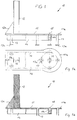
- the seat frame 10 shown in FIGS. 1, 1a and 1b is composed of a base plate 11 secured to a platform 11a.
- the base plate 11 is reinforced, on its underside, by a stiffening frame 14 and provided with support legs 13. With a view to increasing the bearing surface of the support legs 13, these are provided, at their free ends, of support plates 13a.
- a male slide 12 is arranged in a substantially vertical manner.
- the slide 12 consists of a double T profile held in position by a lateral spacer 12a.
- the platform 11a secured to the base plate 11 is substantially circular in shape and provided, in the center, with a connector 15.
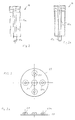
- the connector 15 is provided with a thread 15a into which the tubular central guide shown in detail in Figures 2 and 2a can be screwed.
- the guide 16 comprises an envelope 16a enclosing an inner tube 17.
- the free lower end of the inner tube 17 is provided with a male thread 17a capable of cooperating with the female thread 15a of the connector 15.
- the upper plate 19 ( Figures 3, 3a) is provided with a central coupling bore 21. Reservations 20 are provided concentrically with the central coupling bore 21, these housing bores being reinforced by reinforcement flanges 20a.
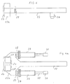
- a guide pin 26, integral with a jack-carrying arm 22 shown in Figures 4 and 4a can be introduced to cooperate with said bore.
- the arm 22 has a longitudinal extent covering almost the total length of the base plate 11, up to the area of the platform 11a and forms with the slide 12 a bracket.
- the guide pin 26 is fixed at a free end of the arm 22 to the underside of the latter.
- the free end of the arm 22 opposite the guide pin 26 is provided with a head element 22a in which is provided a female slide 24 covered by a slide flange 23.
- the female slide 24 is also formed in double T.
- connection eyelets 27 are provided, as shown in FIG. 5, with hinge articulation bores 34a corresponding to the hinge articulation bores 34 in the connection eyelets.
- the jacks 29 are provided with connecting rods 32 provided at their free ends with jack heads 30. At their lower faces, these jack heads 30 are provided with shoes 35 which can be brought into action relationship with the reservations 20 in the upper plate 19.
- the operation of the device which has just been described is indicated in the following: to block or unblock a safety shutter, the shutter is fixed on the base plate 11 comprising the slide 12, on which is positioned at the desired height the arm 22 by its slide 24. The height is chosen according to the height of the well shutter block 16 to be introduced.
- the upper plate 19 On the shutter, the upper plate 19 is placed, which by means of coupling fittings is fixed to the shutter.
- the guide pin 26 provided on the underside of the arm 22 engages in the central bore 21 of the upper plate 19 of which it guarantees the concentricity.
- the hydraulic drive jacks 29 arranged parallel to the arm 22 engage, with their shoes 35, in the reservations 20 of the plate 19. By means of opposite forces deployed by the jacks 29 and acting one in traction, l 'other in compression, the plate 19 and, with it the well shutter can be rotated by about half a turn, so as to loosen or tighten it.
- the cylinders 29 can follow the pivoting movement of the plate 19 and of the reservations 20 in the latter.
- the shutter can be loosened or tightened without endangering the personnel performing the operation.
Landscapes
- Engineering & Computer Science (AREA)
- Geology (AREA)
- Life Sciences & Earth Sciences (AREA)
- Mining & Mineral Resources (AREA)
- Physics & Mathematics (AREA)
- Environmental & Geological Engineering (AREA)
- Fluid Mechanics (AREA)
- General Life Sciences & Earth Sciences (AREA)
- Geochemistry & Mineralogy (AREA)
- Mechanical Engineering (AREA)
- Earth Drilling (AREA)
- Multiple-Way Valves (AREA)
- Pivots And Pivotal Connections (AREA)
- Bridges Or Land Bridges (AREA)
Abstract
Description
L'invention a pour objet un dispositif pour débloquer et bloquer les obturateurs de sécurité annulaires (B.O.P.) pour puits de forage.The invention relates to a device for unlocking and blocking annular safety shutters (B.O.P.) for wellbore.
Les dispositifs de blocage traditionnels présentent normalement un risque élevé d'accident menaçant la main-d'oeuvre occupée à bloquer les puits, étant donné que la rupture d'un câble, le surmenage d une poulie ou la rupture d'une corde de traction peuvent bien se produire.Conventional blocking devices normally present a high risk of accident threatening the workforce engaged in blocking the wells, since the breaking of a cable, overworking of a pulley or the breaking of a traction rope may well happen.
Les dispositifs de blocage conventionnels et connus sont normalement fixés immédiatement sur la tour de forage. A cette fin, une plaque est fixée sur la tête de l'obturateur, tandis qu'une tige de forage munie d'un élément de raccord est liée par soudure à ladite plaque. Cet ensemble est suspendu à l'aide d'un palan ou d'une grue et serré ou desserré à l'aide d'une clé à main de forage. Cependant, ce système présente le désavantage que lorsque l'obturateur est du type à collier celui-ci risque d'être entraîné en rotation de sorte que les joints toriques peuvent être endommagés; lorsque l'obturateur est muni de brides ou de goujons, il existe le risque que les soudures se cassent ou celui d'un dévissage au droit de la tête de tubage ("casing head") d'où endommagement des cales d'ancrage de tubage et de leur étanchéité.Conventional and known blocking devices are normally fixed immediately on the drilling tower. To this end, a plate is fixed to the head of the obturator, while a drill rod provided with a connecting element is connected by welding to said plate. This assembly is suspended using a hoist or crane and tightened or loosened using a drilling hand wrench. However, this system has the disadvantage that when the shutter is of the collar type, it risks being rotated so that the O-rings can be damaged; when the obturator is fitted with flanges or studs, there is a risk that the welds will break or that of unscrewing to the right of the casing head, resulting in damage to the anchoring wedges of casing and their tightness.
En atelier, on a dû prévoir jusqu'ici un point d ancrage convenable en béton armé sur lequel le dispositif de blocage de puits était fixé. Ensuite, un étrier était fixé au dispositif de blocage de puits de sorte que celui-ci puisse être serré ou desserré à l'aide de deux véhicules.In the workshop, a suitable anchor point in reinforced concrete has so far been provided on which the well blocking device was fixed. Then a bracket was attached to the well locking device so that it could be tightened or loosened using two vehicles.
Le document US-A-4 398 598 décrit un dispositifs de desserrage d'un obturateur annulaire de puits comprenant un bâti raccordable à l'obturateur et deux vérins liés de façon articulée d'une part à une plaque supérieure susceptible d'être fixée sur la tête de l'obturateur et d'autre part au bâti de telle sorte que l'actionnement des vérins sollicite en torsion la tête de l'obturateur. Le dispositif n'est pas conçu pour une opération de serrageDocument US-A-4 398 598 describes a device for loosening an annular shutter comprising a frame connectable to the shutter and two jacks linked in an articulated manner on the one hand to an upper plate capable of being fixed on the head of the shutter and on the other hand to the frame so that the actuation of the cylinders biases the head of the shutter. The device is not designed for a tightening operation
L'invention a pour but de créer un dispositif de desserrage et de serrage de blocs-obturateurs de puits garantissant un maximum de sécurité de travail et permettant en même temps une économie de temps sensible.The object of the invention is to create a device for loosening and tightening well shutter blocks guaranteeing maximum work safety and at the same time allowing significant time savings.
A cette fin, l'invention a pour objet un dispositif selon la revendication 1 annexée.To this end, the invention relates to a device according to claim 1 appended.
Selon des caractéristiques avantageuses, les vérins sont disposés essentiellement parallèlement au bras porte-vérins et liés à celui-ci de manière articulée par des charnières; la plaque de base peut être solidaire d'une plate-forme portant un raccord pour le guide central; à sa face inférieure, la plaque de base peut être munie de jambes de soutien et d'un cadre de raidissement.According to advantageous characteristics, the jacks are arranged essentially parallel to the jack-carrying arm and linked to the latter in an articulated manner by hinges; the base plate can be secured to a platform carrying a connector for the central guide; on its underside, the base plate can be provided with support legs and a stiffening frame.
Le dispositif selon l'invention permet une réduction sensible du temps de travail nécessaire au desserrage ou au serrage du bloc-obturateur de puits. En même temps, les risques d'accident et d'endommagement du matériel utilisé sont réduits. Un autre avantage de l'invention réside dans le fait qu'il n'est plus nécessaire d assembler sur site le dispositif de desserrage et de serrage du bloc-obturateur de puits, mais que celui-ci est transportable et peut être monté par exemple sur un autre manchon de sondage.The device according to the invention allows a significant reduction in the working time necessary for loosening or tightening the well shutter block. At the same time, the risk of accident and damage to the equipment used is reduced. Another advantage of the invention resides in the fact that it is no longer necessary to assemble on site the loosening device and tightening of the well shutter block, but that it is transportable and can be mounted for example on another borehole sleeve.
D'autres dispositions avantageuses sont décrites dans les revendications dépendantes. Un mode d'exécution d'un dispositif selon l'invention est représenté, dans les dessins ci- inclus, et décrit ci-après de manière plus détaillée; sont représentés dans la
- figure 1:
- l'élévation d'un bâti d'assise comprenant une plaque de base à laquelle est associée une plate-forme, une glissière de support montée sensiblement de façon perpendiculaire à ladite plaque de base et des jambes de soutien dudit bâti;
- figure 1a:
- le plan du bâti selon la figure 1;
- figure 1b:
- la coupe du bâti selon les figures 1 et 1a;
- figure 2:
- l'élévation d'un guide central tubulaire;
- figure 2a:
- la coupe du guide central selon la figure 2;
- figure 3:
- le plan d'une plaque supérieure pour un dispositif selon l'invention;
- figure 3a:
- l'élévation de la plaque supérieure selon la figure 3;
- figure 4:
- l'élévation d'un bras porte-vérins dans un dispositif selon l'invention, avec un goujon de guidage;
- figure 4a:
- le plan d'un bras porte-vérins selon la figure 4, avec des vérins hydrauliques latéraux;
- figure 5:
- la vue éclatée du bras porte-vérins selon les figures 3 et 4, avec les vérins hydrauliques associés et la plaque supérieure;
- figure 6:
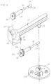
- la vue isométrique d'un bâti d'assise selon la figure 1, avec plaque de base, glissière de support et plate-forme, et avec le guide central associé.
- figure 1:
- the elevation of a seat frame comprising a base plate with which is associated a platform, a support slide mounted substantially perpendicularly to said base plate and support legs of said frame;
- Figure 1a:
- the plan of the frame according to Figure 1;
- Figure 1b:
- the section of the frame according to Figures 1 and 1a;
- figure 2:
- the elevation of a central tubular guide;
- Figure 2a:
- the section of the central guide according to Figure 2;
- figure 3:
- the plane of an upper plate for a device according to the invention;
- Figure 3a:
- the elevation of the upper plate according to Figure 3;
- figure 4:
- the elevation of an actuator arm in a device according to the invention, with a guide stud;
- Figure 4a:
- the plane of a jacking arm according to FIG. 4, with lateral hydraulic jacks;
- figure 5:
- the exploded view of the jack-carrying arm according to FIGS. 3 and 4, with the associated hydraulic jacks and the upper plate;
- figure 6:
- the isometric view of a seat frame according to FIG. 1, with base plate, support slide and platform, and with the associated central guide.
Le bâti d'assise 10 représenté dans les figure 1, 1a et 1b est composé d'une plaque de base 11 solidaire d'une plate-forme 11a. La plaque de base 11 est renforcée, à sa face inférieure, par un cadre de raidissement 14 et munie de jambes de soutien 13. En vue d'augmenter la surface d'appui des jambes de soutien 13, celles- ci sont munies, à leurs extrémités libres, de plaques d'appui 13a.The
Sur la face supérieure de la plaque de base 11 et à son extrémité opposée à la plate-forme 11a, est disposée une glissière mâle 12 de façon sensiblement verticale. La glissière 12 consiste en un profilé en double T tenu en position par une entretoise latérale 12a.On the upper face of the
La plate-forme 11a solidaire de la plaque de base 11 est sensiblement de forme circulaire et munie, au centre, d'un raccord 15.The
Le raccord 15 est muni d'un filetage 15a dans lequel on peut visser le guide central tubulaire représenté de manière détaillée dans les figures 2 et 2a. Le guide 16 comporte une enveloppe 16a renfermant un tube intérieur 17. L'extrémité inférieure libre du tube intérieur 17 est munie d'un filetage mâle 17a susceptible de coopérer avec le filetage femelle 15a du raccord 15.The
La plaque supérieure 19 (figures 3, 3a) est pourvue d'un alésage d'accouplement 21 central. Des réservations 20 sont prévues concentriquement à l'alésage d'accouplement 21 central, ces alésages de logement étant renforcés par des brides de renforcement 20a.The upper plate 19 (Figures 3, 3a) is provided with a central coupling bore 21.
Dans l'alésage d'accouplement 21 central de la plaque supérieure 19, un goujon de guidage 26, solidaire d'un bras porte-vérins 22 représenté dans les figures 4 et 4a peut être introduit pour coopérer avec ledit alésage. Le bras 22 présente une étendue longitudinale couvrant presque la longueur totale de la plaque de base 11, jusque dans le domaine de la plate-forme 11a et forme avec la glissière 12 une potence.In the central coupling bore 21 of the
Le goujon de guidage 26 est fixé à une extrémité libre du bras 22 à la face inférieure de celui-ci. L'extrémité libre du bras 22 opposée au goujon de guidage 26 est munie d'un élément de tête 22a dans lequel est prévue une glissière femelle 24 couverte par une bride de glissière 23. En conformité avec la glissière mâle 12, la glissière femelle 24 est également formée en double T. Par cette glissière 24, le bras 22 est guidé sur la glissière de support 12, de sorte qu'il peut être ajusté convenablement en hauteur. En vue du blocage du bras 22 à la hauteur souhaitée, des coulisseaux latéraux 25 sont associés à la glissière femelle 24.The
Des deux côtés du bras 22 et parallèlement à son étendue longitudinale, on dispose des vérins 29 liés, par l'intermédiaire d'accouplements de vérin 28, à l'élément de tête 22a. A cette fin, l'élément de tête 22a est muni d'oeillets de raccord 27 dans lesquels les accouplements de vérin sont logés de manière pivotable. A cette fin, les oeillets de raccord 27 sont munis, comme le montre la figure 5, d'alésages d'articulation à charnière 34a correspondant aux alésages d'articulation à charnière 34 dans les oeillets de raccord.On both sides of the
Comme également représenté dans la figure 5, les vérins 29 sont munis de bielles 32 pourvues à leurs extrémités libres de têtes de vérin 30. A leurs faces inférieures, ces têtes de vérin 30 sont munies de sabots 35 pouvant être mis en rapport d'action avec les réservations 20 dans la plaque supérieure 19. Le fonctionnement du dispositif qui vient d'être décrit est indiqué dans ce qui suit: pour bloquer ou débloquer un obturateur de sécurite, on fixe l'obturateur sur la plaque de base 11 comportant la glissière 12, sur laquelle est positionné à la hauteur voulue le bras 22 par sa glissière 24. La hauteur est choisie en fonction de la hauteur du bloc-obturateur de puits 16 devant être introduit.As also shown in FIG. 5, the
Sur l'obturateur, la plaque supérieure 19 est placée, laquelle par l'intermédiaire de raccords d'accouplement est fixée sur l'obturateur. Le goujon de guidage 26 prévu à la face inférieure du bras 22 s'engage dans l'alésage central 21 de la plaque supérieure 19 dont il garantit la concentricité. Les vérins 29 à entraînement hydraulique disposés parallèlement au bras 22 s'engagent, avec leurs sabots 35, dans les réservations 20 de la plaque 19. A l'aide de forces opposées déployées par les vérins 29 et agissant l'une en traction, l'autre en compression, la plaque 19 et, avec elle l'obturateur de puits peuvent être tournés d'un demi- tour environ, de sorte à desserrer ou serrer celui-ci. Pendant cette opération, grâce à l'accouplement articulé des vérins 29 à l'élément de tête 22a par l'intermédiaire des oeillets de raccord 27 et les accouplements de vérin 28, les vérins 29 peuvent suivre le mouvement pivotant de la plaque 19 et des réservations 20 dans ce dernier. Ainsi, l'obturateur peut être desserré ou serré sans mettre en danger le personnel effectuant l'opération.
Claims (8)
- Apparatus for tightening and releasing annular well safety plugs, characterized by a ground flange (11) as a supporting structure for safety plug (16), a receiving post (12), a winch supporting arm (22) moving along the receiving post and adapted to be fixed in positions corresponding to the various heights of safety plug (16), a top actuating disc (19) adapted to be attached to the top end of said safety plug (16), a removable tubular central guide member (16) substantially parallel to, and spaced from, receiving post (12), and a pair of winches (20) articulated to said winch supporting arm (22) and in an inserting position relative to top actuating disc (19), said winches (29) being operatively coupled by means of coupling bolts (35) with coupling bores (20) and attached to the aforesaid top actuating disc (19) in a manner that actuation of the aforesaid winches (29) sustains the torquing of the front portion of safety plug (16).
- Apparatus as inclaim 1, characterized in that winches (29) are substantially parallel to winch supporting arm (22) and are articulated thereto by means of winch attachments (27, 28).
- Apparatus as in claims 1 and 2, characterized in that ground support (11) is a one-piece structure with a safety platform (11a) for fixing safety plug (16) in position and has supporting legs (13) and a reinforcing frame (14) at the bottom thereof.
- Apparatus as in claims 1 to 3, characterized by winch supporting arm (22) has a head piece (22a), said head piece (22a) including a guide slot (24) operatively connected with guide jaws (25) of said arm (22) on receiving post (12) being adapted to be raised to, and secured in position at, a suitable height.
- Apparatus as in claims 2 to 4, characterized by winch attachments (28) having lugs (27) associated with head piece (22) of winch supporting arm (22).
- Apparatus as in claims 1 to 5, characterized in that top actuating disc (19) has a central coupling bore (21) adapted to be cooperatively connected to a guide stud (26) provided at the end of winch supporting arm (22).
- Apparatus as in claims 3 to 6, characterized in that safety plug (16) has an inner tube (17) provided with external threads (17a) corresponding to inner threads (15a) of a preventer attachment (15) located on safety platform (11a) of ground flange (11).
- Apparatus as in claim 7, characterized by guide stud (26) being designed to precisely fit in inner tube (17) of central safety plug (16).
Priority Applications (3)
| Application Number | Priority Date | Filing Date | Title |
|---|---|---|---|
| EP90123286A EP0489188B1 (en) | 1990-12-05 | 1990-12-05 | Unit for making-up and breaking out annular blow out preventers of threaded type |
| AT90123286T ATE108510T1 (en) | 1990-12-05 | 1990-12-05 | TOOL FOR MAKING AND TURNING THE THREADED CONNECTION OF PULLOUT VALVES. |
| DE69010689T DE69010689D1 (en) | 1990-12-05 | 1990-12-05 | Tool for making and turning the threaded connection of breakout valves. |
Applications Claiming Priority (1)
| Application Number | Priority Date | Filing Date | Title |
|---|---|---|---|
| EP90123286A EP0489188B1 (en) | 1990-12-05 | 1990-12-05 | Unit for making-up and breaking out annular blow out preventers of threaded type |
Publications (2)
| Publication Number | Publication Date |
|---|---|
| EP0489188A1 EP0489188A1 (en) | 1992-06-10 |
| EP0489188B1 true EP0489188B1 (en) | 1994-07-13 |
Family
ID=8204793
Family Applications (1)
| Application Number | Title | Priority Date | Filing Date |
|---|---|---|---|
| EP90123286A Expired - Lifetime EP0489188B1 (en) | 1990-12-05 | 1990-12-05 | Unit for making-up and breaking out annular blow out preventers of threaded type |
Country Status (3)
| Country | Link |
|---|---|
| EP (1) | EP0489188B1 (en) |
| AT (1) | ATE108510T1 (en) |
| DE (1) | DE69010689D1 (en) |
Family Cites Families (1)
| Publication number | Priority date | Publication date | Assignee | Title |
|---|---|---|---|---|
| US4398598A (en) * | 1981-05-18 | 1983-08-16 | Fabrygel Joe H | Break-out tool for annular type blow-out preventers |
-
1990
- 1990-12-05 DE DE69010689T patent/DE69010689D1/en not_active Expired - Lifetime
- 1990-12-05 EP EP90123286A patent/EP0489188B1/en not_active Expired - Lifetime
- 1990-12-05 AT AT90123286T patent/ATE108510T1/en not_active IP Right Cessation
Also Published As
| Publication number | Publication date |
|---|---|
| EP0489188A1 (en) | 1992-06-10 |
| ATE108510T1 (en) | 1994-07-15 |
| DE69010689D1 (en) | 1994-08-18 |
Similar Documents
| Publication | Publication Date | Title |
|---|---|---|
| US7000503B2 (en) | Support system for power tong assembly | |
| FR2531479A1 (en) | WELL DRILLING WITH TOP CONTROL UNIT | |
| US6907934B2 (en) | Universal top-drive wireline entry system bracket and method | |
| US6138776A (en) | Power tongs | |
| US6065372A (en) | Power wrench for drill pipe | |
| EP1069067B1 (en) | Swivel ring for lifting loads | |
| US20150107853A1 (en) | Stabilizer For Pipe Handling Equipment | |
| GB2289298A (en) | Permanent whipstock | |
| EP0489188B1 (en) | Unit for making-up and breaking out annular blow out preventers of threaded type | |
| FR2745829A1 (en) | Replacement of cable used for suspension or guy wire | |
| US8522412B1 (en) | Extraction tool lifting system | |
| US2242783A (en) | Elevator link and handle | |
| US20030140736A1 (en) | Power tong positioning device | |
| FR2558874A1 (en) | Protective guard rail for people working on roofs | |
| US6827143B2 (en) | Casing centering tool assembly | |
| EP0169749B1 (en) | Mast base articulation | |
| US7198311B1 (en) | Elevator for pipe | |
| EP0161279A1 (en) | Improvements relating to scaffolding and to braces for use in scaffolding | |
| FR2652844A1 (en) | THREADED MEMBRANE ROOF STRUCTURE. | |
| FR2500866A1 (en) | Chain link safety barrier with metal support post - has detachable chain to support connection aiding accident damage repair | |
| FR2597703A1 (en) | Improvements to fertiliser barrels and the like | |
| FR2671131A1 (en) | Self-locking device for lifting and handling tubes, pipes or other elongate elements | |
| WO1991002141A1 (en) | Device for ground consolidation variable-length grouting bolt | |
| FR2470657A1 (en) | HYDRAULIC DEVICE FOR DISASSEMBLING DRILLING TUBES | |
| FR2634803A1 (en) | SUBSEA SUPPORT DEVICE FOR LEGS OF SELF-LIFTING OIL PLATFORMS FOR SEA DRILLING, AND PLATFORMS INCLUDING APPLICATION |
Legal Events
| Date | Code | Title | Description |
|---|---|---|---|
| PUAI | Public reference made under article 153(3) epc to a published international application that has entered the european phase |
Free format text: ORIGINAL CODE: 0009012 |
|
| 17P | Request for examination filed |
Effective date: 19901205 |
|
| AK | Designated contracting states |
Kind code of ref document: A1 Designated state(s): AT BE CH DE DK ES FR GB GR IT LI LU NL SE |
|
| 17Q | First examination report despatched |
Effective date: 19921019 |
|
| RBV | Designated contracting states (corrected) |
Designated state(s): AT BE CH DE ES FR GB GR IT LI LU NL SE |
|
| GRAA | (expected) grant |
Free format text: ORIGINAL CODE: 0009210 |
|
| AK | Designated contracting states |
Kind code of ref document: B1 Designated state(s): AT BE CH DE ES FR GB GR IT LI LU NL SE |
|
| PG25 | Lapsed in a contracting state [announced via postgrant information from national office to epo] |
Ref country code: IT Free format text: LAPSE BECAUSE OF FAILURE TO SUBMIT A TRANSLATION OF THE DESCRIPTION OR TO PAY THE FEE WITHIN THE PRE;WARNING: LAPSES OF ITALIAN PATENTS WITH EFFECTIVE DATE BEFORE 2007 MAY HAVE OCCURRED AT ANY TIME BEFORE 2007. THE CORRECT EFFECTIVE DATE MAY BE DIFFERENT FROM THE ONE RECORDED.SCRIBED TIME-LIMIT Effective date: 19940713 Ref country code: ES Free format text: THE PATENT HAS BEEN ANNULLED BY A DECISION OF A NATIONAL AUTHORITY Effective date: 19940713 Ref country code: GB Effective date: 19940713 Ref country code: NL Effective date: 19940713 Ref country code: GR Free format text: LAPSE BECAUSE OF FAILURE TO SUBMIT A TRANSLATION OF THE DESCRIPTION OR TO PAY THE FEE WITHIN THE PRESCRIBED TIME-LIMIT Effective date: 19940713 Ref country code: DE Effective date: 19940713 Ref country code: AT Effective date: 19940713 |
|
| REF | Corresponds to: |
Ref document number: 108510 Country of ref document: AT Date of ref document: 19940715 Kind code of ref document: T |
|
| REF | Corresponds to: |
Ref document number: 69010689 Country of ref document: DE Date of ref document: 19940818 |
|
| PG25 | Lapsed in a contracting state [announced via postgrant information from national office to epo] |
Ref country code: SE Effective date: 19941013 |
|
| NLV1 | Nl: lapsed or annulled due to failure to fulfill the requirements of art. 29p and 29m of the patents act | ||
| PG25 | Lapsed in a contracting state [announced via postgrant information from national office to epo] |
Ref country code: BE Effective date: 19941231 Ref country code: CH Effective date: 19941231 Ref country code: LU Free format text: LAPSE BECAUSE OF NON-PAYMENT OF DUE FEES Effective date: 19941231 Ref country code: LI Effective date: 19941231 |
|
| GBV | Gb: ep patent (uk) treated as always having been void in accordance with gb section 77(7)/1977 [no translation filed] |
Effective date: 19941013 |
|
| GBV | Gb: ep patent (uk) treated as always having been void in accordance with gb section 77(7)/1977 [no translation filed] |
Effective date: 19940713 |
|
| GBV | Gb: ep patent (uk) treated as always having been void in accordance with gb section 77(7)/1977 [no translation filed] |
Free format text: DATE CORRECTED TO 940713 |
|
| PLBE | No opposition filed within time limit |
Free format text: ORIGINAL CODE: 0009261 |
|
| STAA | Information on the status of an ep patent application or granted ep patent |
Free format text: STATUS: NO OPPOSITION FILED WITHIN TIME LIMIT |
|
| BERE | Be: lapsed |
Owner name: ENTREPRISE NATIONALE DES TRAVAUX AUX PUITS ENTP Effective date: 19941231 |
|
| 26N | No opposition filed | ||
| PG25 | Lapsed in a contracting state [announced via postgrant information from national office to epo] |
Ref country code: FR Effective date: 19950831 |
|
| REG | Reference to a national code |
Ref country code: CH Ref legal event code: PL |
|
| REG | Reference to a national code |
Ref country code: FR Ref legal event code: ST |