EP0487896A1 - Mehrachsige Werkzeugpositioniereinrichtung - Google Patents
Mehrachsige Werkzeugpositioniereinrichtung Download PDFInfo
- Publication number
- EP0487896A1 EP0487896A1 EP19910118000 EP91118000A EP0487896A1 EP 0487896 A1 EP0487896 A1 EP 0487896A1 EP 19910118000 EP19910118000 EP 19910118000 EP 91118000 A EP91118000 A EP 91118000A EP 0487896 A1 EP0487896 A1 EP 0487896A1
- Authority
- EP
- European Patent Office
- Prior art keywords
- axis
- saddle
- ram
- combination
- column
- Prior art date
- Legal status (The legal status is an assumption and is not a legal conclusion. Google has not performed a legal analysis and makes no representation as to the accuracy of the status listed.)
- Withdrawn
Links
- NJPPVKZQTLUDBO-UHFFFAOYSA-N novaluron Chemical compound C1=C(Cl)C(OC(F)(F)C(OC(F)(F)F)F)=CC=C1NC(=O)NC(=O)C1=C(F)C=CC=C1F NJPPVKZQTLUDBO-UHFFFAOYSA-N 0.000 abstract description 8
- 230000000712 assembly Effects 0.000 description 15
- 238000000429 assembly Methods 0.000 description 15
- 230000004044 response Effects 0.000 description 6
- 239000012636 effector Substances 0.000 description 4
- 239000012530 fluid Substances 0.000 description 3
- 230000006870 function Effects 0.000 description 3
- 230000006872 improvement Effects 0.000 description 3
- 238000009434 installation Methods 0.000 description 3
- 238000003754 machining Methods 0.000 description 3
- 239000003638 chemical reducing agent Substances 0.000 description 2
- 230000000694 effects Effects 0.000 description 2
- 238000004519 manufacturing process Methods 0.000 description 2
- 238000002360 preparation method Methods 0.000 description 2
- 210000000707 wrist Anatomy 0.000 description 2
- 229910000831 Steel Inorganic materials 0.000 description 1
- 238000005452 bending Methods 0.000 description 1
- 230000015572 biosynthetic process Effects 0.000 description 1
- 238000005266 casting Methods 0.000 description 1
- 230000008859 change Effects 0.000 description 1
- 238000005520 cutting process Methods 0.000 description 1
- 238000005553 drilling Methods 0.000 description 1
- 238000005516 engineering process Methods 0.000 description 1
- 238000000227 grinding Methods 0.000 description 1
- 230000003116 impacting effect Effects 0.000 description 1
- 238000003780 insertion Methods 0.000 description 1
- 230000037431 insertion Effects 0.000 description 1
- 239000002184 metal Substances 0.000 description 1
- 238000003801 milling Methods 0.000 description 1
- 125000006850 spacer group Chemical group 0.000 description 1
- 239000010959 steel Substances 0.000 description 1
- 230000001360 synchronised effect Effects 0.000 description 1
Images


Classifications
-
- B—PERFORMING OPERATIONS; TRANSPORTING
- B25—HAND TOOLS; PORTABLE POWER-DRIVEN TOOLS; MANIPULATORS
- B25J—MANIPULATORS; CHAMBERS PROVIDED WITH MANIPULATION DEVICES
- B25J19/00—Accessories fitted to manipulators, e.g. for monitoring, for viewing; Safety devices combined with or specially adapted for use in connection with manipulators
- B25J19/0004—Braking devices
-
- B—PERFORMING OPERATIONS; TRANSPORTING
- B23—MACHINE TOOLS; METAL-WORKING NOT OTHERWISE PROVIDED FOR
- B23Q—DETAILS, COMPONENTS, OR ACCESSORIES FOR MACHINE TOOLS, e.g. ARRANGEMENTS FOR COPYING OR CONTROLLING; MACHINE TOOLS IN GENERAL CHARACTERISED BY THE CONSTRUCTION OF PARTICULAR DETAILS OR COMPONENTS; COMBINATIONS OR ASSOCIATIONS OF METAL-WORKING MACHINES, NOT DIRECTED TO A PARTICULAR RESULT
- B23Q1/00—Members which are comprised in the general build-up of a form of machine, particularly relatively large fixed members
- B23Q1/25—Movable or adjustable work or tool supports
- B23Q1/44—Movable or adjustable work or tool supports using particular mechanisms
- B23Q1/48—Movable or adjustable work or tool supports using particular mechanisms with sliding pairs and rotating pairs
-
- B—PERFORMING OPERATIONS; TRANSPORTING
- B25—HAND TOOLS; PORTABLE POWER-DRIVEN TOOLS; MANIPULATORS
- B25J—MANIPULATORS; CHAMBERS PROVIDED WITH MANIPULATION DEVICES
- B25J9/00—Programme-controlled manipulators
- B25J9/02—Programme-controlled manipulators characterised by movement of the arms, e.g. cartesian coordinate type
-
- B—PERFORMING OPERATIONS; TRANSPORTING
- B25—HAND TOOLS; PORTABLE POWER-DRIVEN TOOLS; MANIPULATORS
- B25J—MANIPULATORS; CHAMBERS PROVIDED WITH MANIPULATION DEVICES
- B25J9/00—Programme-controlled manipulators
- B25J9/10—Programme-controlled manipulators characterised by positioning means for manipulator elements
- B25J9/1005—Programme-controlled manipulators characterised by positioning means for manipulator elements comprising adjusting means
- B25J9/101—Programme-controlled manipulators characterised by positioning means for manipulator elements comprising adjusting means using limit-switches, -stops
-
- Y—GENERAL TAGGING OF NEW TECHNOLOGICAL DEVELOPMENTS; GENERAL TAGGING OF CROSS-SECTIONAL TECHNOLOGIES SPANNING OVER SEVERAL SECTIONS OF THE IPC; TECHNICAL SUBJECTS COVERED BY FORMER USPC CROSS-REFERENCE ART COLLECTIONS [XRACs] AND DIGESTS
- Y10—TECHNICAL SUBJECTS COVERED BY FORMER USPC
- Y10T—TECHNICAL SUBJECTS COVERED BY FORMER US CLASSIFICATION
- Y10T29/00—Metal working
- Y10T29/51—Plural diverse manufacturing apparatus including means for metal shaping or assembling
- Y10T29/5104—Type of machine
- Y10T29/5105—Drill press
- Y10T29/5107—Drilling and other
-
- Y—GENERAL TAGGING OF NEW TECHNOLOGICAL DEVELOPMENTS; GENERAL TAGGING OF CROSS-SECTIONAL TECHNOLOGIES SPANNING OVER SEVERAL SECTIONS OF THE IPC; TECHNICAL SUBJECTS COVERED BY FORMER USPC CROSS-REFERENCE ART COLLECTIONS [XRACs] AND DIGESTS
- Y10—TECHNICAL SUBJECTS COVERED BY FORMER USPC
- Y10T—TECHNICAL SUBJECTS COVERED BY FORMER US CLASSIFICATION
- Y10T29/00—Metal working
- Y10T29/51—Plural diverse manufacturing apparatus including means for metal shaping or assembling
- Y10T29/5152—Plural diverse manufacturing apparatus including means for metal shaping or assembling with turret mechanism
- Y10T29/5154—Plural diverse manufacturing apparatus including means for metal shaping or assembling with turret mechanism tool turret
-
- Y—GENERAL TAGGING OF NEW TECHNOLOGICAL DEVELOPMENTS; GENERAL TAGGING OF CROSS-SECTIONAL TECHNOLOGIES SPANNING OVER SEVERAL SECTIONS OF THE IPC; TECHNICAL SUBJECTS COVERED BY FORMER USPC CROSS-REFERENCE ART COLLECTIONS [XRACs] AND DIGESTS
- Y10—TECHNICAL SUBJECTS COVERED BY FORMER USPC
- Y10T—TECHNICAL SUBJECTS COVERED BY FORMER US CLASSIFICATION
- Y10T409/00—Gear cutting, milling, or planing
- Y10T409/30—Milling
- Y10T409/306664—Milling including means to infeed rotary cutter toward work
- Y10T409/307672—Angularly adjustable cutter head
-
- Y—GENERAL TAGGING OF NEW TECHNOLOGICAL DEVELOPMENTS; GENERAL TAGGING OF CROSS-SECTIONAL TECHNOLOGIES SPANNING OVER SEVERAL SECTIONS OF THE IPC; TECHNICAL SUBJECTS COVERED BY FORMER USPC CROSS-REFERENCE ART COLLECTIONS [XRACs] AND DIGESTS
- Y10—TECHNICAL SUBJECTS COVERED BY FORMER USPC
- Y10T—TECHNICAL SUBJECTS COVERED BY FORMER US CLASSIFICATION
- Y10T409/00—Gear cutting, milling, or planing
- Y10T409/30—Milling
- Y10T409/30784—Milling including means to adustably position cutter
- Y10T409/307952—Linear adjustment
- Y10T409/308232—Linear adjustment and angular adjustment
Definitions
- This invention is directed generally to mobile, remotely controlled automatic machine tool actuators and positioning devices or industrial “robots” and more specifically to improvements for expanding the working capability and versatility thereof.
- robots capable of driving and positioning a variety of machine tools in selected spacial positions have gained popular acceptance for a wide variety of industrial applications.
- Such robots are capable in many instances of substantially unmanned automatic operation, including the ability to automatically change tooling whereby to carry out a host of pre-programmed machining operations such as drilling, milling, cutting, grinding, impacting, routing, measuring, fastener installations, inspecting, locating and other related tasks.
- Robotic machines of this order must be highly accurate in positioning and operating the selected tooling and as a consequence they are generally heavy, relatively cumbersome, rigid and costly structures which, however, are uniquelyacious and thus capable of substantially uninterrupted, dependable, highly accurate, economical and cost effective production of consistently high quality products.
- each robot being of Cartesian structure with mutually perpendicular X, Y and Z axes, the X axis being defined by the machine's associated horizontal linear bedways; the Y axis being defined by a central vertical column which carries a horizontal, linearally moveable power ram defining the Z axis of movement.
- An articulated wrist or twist head is mounted at one end of the ram and comprises a pair of transverse rotary movement axes.
- the vertical column preferably is rotatable about its vertical axis for defining a third rotary axis.
- the twist head of each of the robots is designed to accept selected end effectors carrying specific tooling for accomplishing required tasks with such tooling being capable of linear extension and retraction movements in accordance with corresponding linear movements of a rotatably driven quill.
- This invention is directed to a multi-axis, remotely controlled, robotic machining center of Cartesian structure having mutually perpendicular X, Y and Z linear movement axes, namely a horizontal X axis, a vertical Y axis and a horizontal Z axis with the machining center being moveable along horizontal rails or guideways definitive of the X axis and comprising a vertical pedestal definitive of the Y axis and carrying a horizontally disposed linearally moveable ram defining the Z axis.
- the ram is equipped to carry working tools or end effectors on an articulated wrist or twist head attached to one end thereof and definitive of perpendicular rotary movement axes as well as a linear movement axis coincident with the Z axis, but independent thereof, as defined by an axially moveable rotatable tool driving quill.
- the ram is supported on the vertical pedestal for movement along the linear Y axis thereof and also is rotatably supported on that pedestal for rotational movement in a vertical plane by means of a mounting system which includes positive stop members capable of accurately positioning the ram in two horizontal operating positions and a brake system for positively holding the ram in such positions so that tooling carried by the ram is capable of being moved to and operatively positioned at eight of two diametrically opposite working positions.
- a mounting system which includes positive stop members capable of accurately positioning the ram in two horizontal operating positions and a brake system for positively holding the ram in such positions so that tooling carried by the ram is capable of being moved to and operatively positioned at eight of two diametrically opposite working positions.
- a principle object of this invention is to provide an improved robotic machining center of Cartesian structure in which an operationally horizontal, linearally moveable ram is adapted to rotate in a vertical plane about a horizontal axis between two diametrically opposed horizontal operating positions.
- Another important object of this invention is to provide an improved robotic machining center of the order set forth in the preceding object in which the ram is selectively held in either of its two operating positions by positive acting brake means.
- a still further object of this invention is to provide an improved robotic machining center of Cartesian structure having a linearally moveable ram aligned normal to a horizontal movement axis of the robot; the ram being equipped to carry tooling at one outer end thereof and being rotatably moveable through a prescribed vertical arc whereby to reversely position its tool carrying head on opposite sides of the robot's vertical Y axis.
- Still another important object of this invention is to provide an improved rotatable support for a horizontal ram in an industrial robot whereby the ram is rotatably moveable in a vertical plane through and along a prescribed arc of movement.
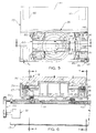
- an automatic, remotely controlled, mobile robotic machining center comprises a horizontal base 11 supporting a vertically extending column 12 which in turns supports a horizontal ram 13 along one side thereof.
- a robotic machining center is adapted to run along a pair of horizontally extending parallel rails 14, 14 or bedways definitive of the X axis of the Cartesian structured robot.
- Base 11 is undersupported on the rails or bedways 14 and driven linearally therealong, as selected, by appropriate power drive means, such as a rack and pinion drive (not shown).
- the vertical Y axis of the robot is defined by the column 12 and the Z axis is defined by the operationally horizontal ram 13, which also is power actuated along the axis Z to extend or retract, relative to the vertical column 12 as desired.
- the ram 13 is mounted to rotatably move relative to column 12 about a central A axis which defines a first rotational axis of movement.
- a second rotational movement axis for the machine is provided by a twist head assembly 15 (see Fig. 1B), which is joined to a main head 16 for the ram and provides movement about a rotational axis B.
- the twist head normally carries a rotatably driven quill 17 to which appropriate operating tools are attached.
- the main head 16 in turn is adapted to be coupled to the outer end of the ram 13 and more particularly to a rotatable connector assembly 18 definitive of a third rotational axis C.
- the robotic machining center 10 comprises three linearally moveable Cartesian axes X, Y and Z and at least three rotational axes A, B and C to effectuate desired spacial positioning and movements of tooling attached to twist head 15.
- the base 11 supports an operator station 20 adjacent ram 13, a rivet buffer station 21 located on the opposite side of the vertical column 12 from ram 13 and alongside a rivet feeder station 22.
- the vertical column 12 supports a pair of rotatable multi-position tool holders 23 and 24 on the opposite sides thereof (see Fig. 2). These holders cooperate with pivotally moveable tool changers 25 whereby the various tools carried by the holders 23 and 24 on each side of the column 12 may be selectively positioned in the quill 17 of the twist head 15 for selected machining operations.
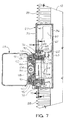
- a vertically driven Y-axis saddle 27 is moveable vertically along one side of column 12 by an appropriate rack and pinion drive system (not illustrated herein) and a rail guide system.
- Appropriate bellows 28, 28 connect the saddle 27 with the upper cap end 29 of the column 12 and with the base 11 to enclose the saddle drive and guide system while accommodating vertical movements of the saddle 27 along the Y axis.
- the ram 13 is in turn supported on a rotatable saddle 30, which is rotatably carried by the vertically moveable saddle 27, as will be described presently.
- the linearally moveable Y axis saddle 27 comprises a generally rectangular parallelopiped fabricated or cast hollow structure including a front cover wall 35, a central rear wall 36 flanked by co-planar offset portions 37, 37 and co-planar portions 37a, 37a, parallel side walls 38, 38 at opposite or lateral margins or the saddle structure and plural intervening spaced rib walls 39-46 which extend between the front wall 35 and the rear wall 36 and its offset portions, as best illustrated in Fig. 6 of the drawings.
- the front and back walls of the hollow saddle structure are interjoined by top and bottom walls 47 and 48, respectively, and an intermediate transverse support wall 49, as shown in Figs. 7 and 8 of the drawings.
- Such hollow saddle structure is adapted to be mounted over one lateral or side face of the central column 12 with the central rear wall 36 thereof located in an elongated, rectangular shaped recess 50 of the column and the side walls 38, 38 thereof extending beyond front and back walls 51 and 52 of the column 12 (see Fig. 6).
- the saddle structure 27 is equipped with four rail pads 55 adjacent the four rear corners of thereof and which are bolted to the secondary offset wall portions 37a (see Fig. 6). These pads are adapted to receive linear guide rails 56 which in turn are affixed to the side wall 57 of column 12 to formulate a pair of parallel spaced, vertically disposed guide means restricting movement of the saddle 27 along the Y axis of the robotic machining center. Actuation of the saddle 27 along the guide rails is effected by means of rack and pinion drive means or suitable equivalents thereof (not shown).
- the guide pads and rails utilized for this interconnection of the saddle 27 with column 12 comprise linear motion roller guides in which cylindrical rollers run along opposing track rails 56 to achieve endless linear motion while circulating in a sliding unit.
- the pads 55 constitute such sliding units to provide low friction slidable interconnection for mounting the saddle structure 27.
- Such linear motion roller guides are available commercially, as for example from Nipon Thompson and Company Ltd., Tokyo, Japan.
- the Y axis saddle 27 is adapted to be moved vertically and selectively located along the length of the rails 56 whereby to vertically position the saddle 27 and ram 13 attached thereto. Further it will be understood, particularly with reference to Figs. 1 and 7, that the top and bottom walls 47 and 48 of saddle 27 are coupled to the bellows 28, 28 which protectively enclose the guide rails 56 throughout the range of movements for the Y axis saddle.
- saddle 27 incorporates means for supporting the rotatable saddle 30, as well as means for rotatably driving the ram 13 between its two horizontal operating positions, as previously noted.
- means for supporting the rotatable saddle 30, as well as means for rotatably driving the ram 13 between its two horizontal operating positions as previously noted.
- specific reference is now made to Figs. 7, 8 and 9 of the drawings.
- a sevo motor 60 and gear reducer 61 are mounted internally of the hollow saddle structure 27; the gear reducer 61 having a drive shaft 62 on which is mounted a driving bevel pinion gear 63.
- Elements 60-63 are supported on the internal transverse support 49 of saddle 27.
- the drive system so provided is responsive to computer generated or manual control signals, as appropriate, to rotatably drive the pinion gear 63 in appropriate direction to effectuate desired rotational movement of the ram 13 in operation.
- bevel pinion 63 engages the teeth of a large bevel ring gear 64 which is connected as by bolts 65 to a split bearing support ring 66 over intervening annular shims 67.
- ring 66 is adapted to receive the inner race of a cross roller bearing assembly 68 while the outer race of such assembly is held in an appropriate annular seat portion 69 cast or fabricated with front wall 35 and support bracket 49.
- An annular retainer flange 70 is joined to wall 35 by plural bolts 71 so as to border a central circular opening 72 formed through the front wall and lock the outer race of bearing assembly 68 in position (see Figs. 7 and 9).
- Bearing assembly 68 is designed to carry radial, thrust and bending moment loads simultaneously and incorporates roller bearings which are arranged cross wise by appropriate retainers to roll on right angle V grooves provided in the outside diameter surface of the inner bearing ring and the inner diameter surface of the outer ring.
- Such a bearing assembly is commercially available from T. H. K. Co. Ltd., Tokyo, Japan and is of the order described in United States Patent No. 4,479,683, issued October 30, 1984.
- the bearing support ring 66 is split with an outer annular portion 66a thereof intertied to the remainder of ring 66 by cap or machine bolts 73 whereby to tightly grip and hold the inner race of the bearing assembly 68 therebetween.
- the outer annular portion 66a of the support ring 66 is cast integrally with or otherwise fixed to the rotatable saddle 30 so that the latter along with the intervening structure 66 and ring gear 65 are moveable as a unit in response to driving activity of pinion 63; such rotatably moveable structure being supported by the single annular cross bearing 68.
- the Y-axis saddle assembly 27 carries four brake assemblies 75, 75 which are disposed in generally rectangular array at equal radial distances from the center of central opening 72 in front wall 35.
- the saddle assembly 27 also includes two hard stop assemblies 76, 76 disposed at the lower corners of the saddle's front wall 35. Such stop assemblies cooperate with the rotatable saddle 30 for limiting the latter's rotational movement as will appear in greater detail presently.
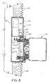
- the rotatable saddle comprises a unitary steel casting or, if desired, such may be a fabricated weldment of relatively heavy, rigid structure.
- saddle 30 comprises a rigid metal body 80 of generally rectangular formation, as best shown in Fig. 11, and includes a pair of projecting ear portions 81, 81 at one end which support keyed flange pads 82, 82.
- Such pads seat in recesses 83 formed inwardly of the rear face 84 of body 80 so that the keyed pads 82 lie flush with the face 84.
- two additional keyed pads 82, 82 are located in recesses 83 formed inwardly of the rear face of the saddle body 80 adjacent the right hand end as viewed in Fig. 11.
- the four pads 82 are located at equal radial distances from the center of bearing 68 which defines the A axis of rotation for saddle 30.
- Each of the keyed pads 82 is distinguished by a slotted opening of T-shaped cross section indicated at 85 (Figs. 11 and 13); such recesses being formulated along an arc of uniform radial distance from the A axis of rotation.
- the T-slots 85 in the two right hand disposed keyed pads 82 as viewed in Fig. 11 are further interconnected by a continuing arcuate channel 86 extending across the back face of body 80 and formulated at the same radial distance from the A axis and same width as the T-slots 85, for purposes which will become more clear in description to follow. In brief, however, the T-slots in pads 82 cooperate with the brake assemblies 75.
- each of the front four corners of the saddle body 80 carries a rectangular slide pad 90 which is coupled to one or a pair of parallel linear slide rails 91 fixed to the adjacent side of ram 13 to define a pair of parallel slide ways definitive of the Z-axis of movement for ram 13.
- the slide pads and rails 90, 91 correspond to the Y-axis pads and rails 55 and 56 heretofore described. As shown best in Figs.
- the pads 90 are fixed to body 80 of the saddle 30 by means of machine bolts 92 while the cooperating rails 91 are coupled to the ram 13 by bolts 93. More specifically as shown best in Figs. 7 and 8, the slide pads 90 seat in shallow recesses 94 formed inwardly of the front face of the moveable saddle body and are held in such recesses by gibs 95 plus the bolts 92 as heretofore noted.
- the front face of the moveable saddle 30 also includes a central lengthwise extending recessed channel 98 (see Fig. 5) which is receptive of a ball screw 99 that extends along one side of ram 13 and is rotatably supported near its opposite ends by bearing carrying bracket means 100.
- a drive motor 101 and toothed belt drive means 102 at the inner end of the ram 13 serve to rotatably drive screw 99 in response to selected energization of motor 101.
- the ball screw 99 is engaged by a ball nut 103 which is held by bracket means 104 fixed to the saddle body 80 by bolts 105 (see Fig. 5).
- the Y-axis saddle assembly 27 includes four brake assemblies 75 which cooperate with the keyed pads 82 of the rotatably moveable saddle 30.
- the brake assemblies operate to positively hold the saddle 30 in selected positions, particularly the horizontal operating positions for ram 13.
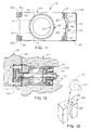
- Figs. 11, 12 and 13 of the drawings To better understand this relationship and the working of the brake means, specific reference is now made to Figs. 11, 12 and 13 of the drawings.
- each pad 82 is secured in their appropriate sockets 83 in the rear face of the moveable saddle body 80 as illustrated in Fig. 11 and more particularly in Fig. 12.
- Each pad 82 is secured in place by a plurality of bolts 108 and aligned registeringly with one of the brake assemblies 75 associated with the Y-axis saddle in a horizontal position of ram 13.
- each of the pads 82 is positioned in its respective socket 83 over a spacer 109 whereby the outer face of the pad is aligned flush with the rear face 84 of the saddle body 80, as shown.
- Each brake assembly 75 as best shown in Fig. 12, comprises a generally cylindrical piston housing 110 which fits snuggly into a appropriate cylindrical opening 111 in the Y-axis saddle 27.
- Piston housing 110 includes an interior cylindrical chamber 112 receptive of a cup spring assembly 113.
- a piston rod 114 extends the full length of the piston housing 110 and coaxially through the spring assembly 113.
- Rod 114 is supported adjacent its outer end by bearing means 115 located in a square flanged end portion 110a of the piston housing and fixed to the latter by bolts (not shown).
- An enlarged cylindrical head portion 116 is formed at the outer end of shaft 114 to fit into the slotted openings 85 of adjacently opposed keyed pads 82 (see Fig. 13).
- the inner end of rod 114 is formed with a reduced diameter portion 117 that extends through a cylindrical piston 118 which is pressed onto rod portion 117 to engage one end of the spring assembly 113 in chamber 112 and abut the shoulder formed by the junction or rod 114 and its smaller diametered portion 117.
- the cylindrical piston 118 fits snuggly against the walls of chamber 112 and carries an O-ring seal 119 or the like to effectuate sealed engagement with the walls thereof.
- rod portion 117 is surrounded by a cylindrical bushing 120 carried within a cylindrical bearing 121 disposed coaxially within the body of an end cap 122 that is bolted to the inner end of housing 110 by bolts 123.
- Another O-ring seal 124 provides sealed engagement between the end cap 122 and bushing 120 while a third O-ring seal 125 provides sealed engagement between the end cap 122 and the interior walls of the body chamber 112.
- a lock nut 125 secures the bushing 120 and piston 118 to piston rod 114 to effect conjoint movement of such parts axially of chamber 112 in response to the application of suitable pressurized hydraulic fluid or the like to the back side of piston 118.
- annular chamber 127 formed between the end cap 122 and piston 118 communicates with fluid inlet 128.
- application of pressurized fluid to chamber 127 serves to advance piston 118 against the spring assembly 113 to move the head portion 116 of the piston rod axially away from flange portion 129 of the keyed pad 82 to release the latter.
- relief of the hydraulic pressure within the chamber 127 permits the spring means 113 to pull the head portion 116 against the flange portion 129 of the keyed pad which forces the pad tightly against an annular shim 130 disposed between the keyed pad 82 and the flange portion 110a of the piston housing 110.
- saddle 30 is adapted to be rotated about its A axis for the purpose of reversely positioning ram 13, so that the latter may service work assemblies in adjacent aisles of a work cell.
- the rotatable support system previously described permits selected rotational movement of saddle 30 and the brake systems 75 and pads 82 serve to lock saddle 30 in each of two selected horizontal ram operating positions.
- positive hard stop systems 76 are provided.
- each stop system comprises a bracket 132 having a mounting plate 133 formed integrally with a right angularly related mounting arm 134, the latter of which supports a vertically adjustable stop 135 and adjusting collar 136.
- Plate 133 and extending arm 134 are fixed to the side and front walls of the Y-axis saddle by bolts 137 and 138 respectively, so that stop 135 is located outwardly of the outside of wall 35 to confront the rotatable saddle 30.
- the rotatable saddle 30 (see Fig. 11) has two hard stop discs 140, and 141 fixed to its top and bottom right hand corners, respectively. Each of these disc is aligned to contact one of the stops 135, at the desired limits of rotational movement for saddle 30.
- the top corner mounted hard stop disc 140 on saddle 30 as viewed in Fig. 11 will rest against the stop 135 located at the bottom right hand corner of the Y-axis saddle 27 as seen in Fig. 9 in one operating position for ram 13.
- the bottom disc 141 will engage the left hand stop pad 135 of Fig. 9 in the other or opposite horizontal operating position for ram 13 (see Fig. 5 for the frontal assembled relation of saddles 27 and 30).
Applications Claiming Priority (2)
| Application Number | Priority Date | Filing Date | Title |
|---|---|---|---|
| US07/621,076 US5084951A (en) | 1990-11-30 | 1990-11-30 | Multi-axis tool positioner |
| US621076 | 1990-11-30 |
Publications (1)
| Publication Number | Publication Date |
|---|---|
| EP0487896A1 true EP0487896A1 (de) | 1992-06-03 |
Family
ID=24488613
Family Applications (1)
| Application Number | Title | Priority Date | Filing Date |
|---|---|---|---|
| EP19910118000 Withdrawn EP0487896A1 (de) | 1990-11-30 | 1991-10-22 | Mehrachsige Werkzeugpositioniereinrichtung |
Country Status (3)
| Country | Link |
|---|---|
| US (1) | US5084951A (de) |
| EP (1) | EP0487896A1 (de) |
| CA (1) | CA2054628A1 (de) |
Cited By (2)
| Publication number | Priority date | Publication date | Assignee | Title |
|---|---|---|---|---|
| FR2746045A1 (fr) * | 1996-03-15 | 1997-09-19 | S O C O A Societe De Conceptio | Rotaxe mobile |
| EP1206991A2 (de) * | 2000-11-10 | 2002-05-22 | Schwäbische Werkzeugmaschinen GmbH | Werkzeugmaschine und Steuerverfahren dafür |
Families Citing this family (9)
| Publication number | Priority date | Publication date | Assignee | Title |
|---|---|---|---|---|
| US5560102A (en) * | 1992-10-13 | 1996-10-01 | The Boeing Company | Panel and fuselage assembly |
| US5836068A (en) * | 1997-04-14 | 1998-11-17 | Northrop Grumman Corporation | Mobile gantry tool and method |
| US6257109B1 (en) * | 1997-08-29 | 2001-07-10 | Citizen Watch Co., Ltd. | Automatic lathe and method of controlling same |
| US6257111B1 (en) * | 1998-04-07 | 2001-07-10 | Citizen Watch Co., Ltd. | Automatic lathe and control method therefor |
| JP3256879B2 (ja) * | 1999-07-01 | 2002-02-18 | ホーコス株式会社 | 工作機械 |
| US6899511B2 (en) | 2000-10-19 | 2005-05-31 | Rapid Development Services, Inc, Mo. Corp | Modular robotic device and manufacturing system |
| ITTO20030632A1 (it) * | 2003-08-11 | 2005-02-12 | Comau Spa | Unita' di lavorazione meccanica ad asportazione di truciolo, |
| DE202014103569U1 (de) * | 2013-08-01 | 2014-10-30 | Grob-Werke Gmbh & Co. Kg | Maschinenkonzept mit Bearbeitungsmaschine |
| JP7028826B2 (ja) * | 2019-05-22 | 2022-03-02 | 株式会社スギノマシン | 単軸ロボット |
Citations (8)
| Publication number | Priority date | Publication date | Assignee | Title |
|---|---|---|---|---|
| US3294256A (en) * | 1964-04-22 | 1966-12-27 | Gbl Corp | Article handling apparatus |
| US3483796A (en) * | 1967-06-21 | 1969-12-16 | Innocenti Soc Generale | Angularly adjustable headstock attachment for use on machine tools |
| DE1652721A1 (de) * | 1968-02-28 | 1971-04-08 | Schiess Ag | Universal-Werkzeugmaschine |
| US3665148A (en) * | 1971-04-07 | 1972-05-23 | Gen Motors Corp | Six-axis manipulator |
| DE2301423A1 (de) * | 1973-01-12 | 1974-07-25 | Fischer Brodbeck Gmbh | Handhabungsgeraet |
| US3954188A (en) * | 1973-12-26 | 1976-05-04 | Prab Conveyors, Inc. | Universal transfer device |
| EP0076231A2 (de) * | 1981-09-24 | 1983-04-06 | Franz Schäfer | Verfahren und Einrichtung zum seriellen Bearbeiten und/oder zur Montage von Werkstücken |
| EP0111565A1 (de) * | 1982-05-12 | 1984-06-27 | Matsushita Electric Industrial Co., Ltd. | Industrieller roboter |
Family Cites Families (7)
| Publication number | Priority date | Publication date | Assignee | Title |
|---|---|---|---|---|
| BE506447A (de) * | 1950-10-18 | |||
| US2750851A (en) * | 1951-05-30 | 1956-06-19 | Machines Outils Et D Outil S P | Milling and boring machine with a tiltable headstock |
| US3823645A (en) * | 1973-05-23 | 1974-07-16 | N Sjundjukov | Milling machine |
| FR2299116A1 (fr) * | 1973-09-11 | 1976-08-27 | Habib Robert | Machine-outil |
| SU610618A1 (ru) * | 1975-02-14 | 1978-06-15 | Ленинградское Специальное Конструкторское Бюро Тяжелых И Уникальных Станков | Станок дл обработки гребных винтов |
| US4543020A (en) * | 1983-05-16 | 1985-09-24 | Usm Corporation | Method of manufacturing large gears |
| US4955119A (en) * | 1989-07-11 | 1990-09-11 | Imta | Multi-task end effector for robotic machining center |
-
1990
- 1990-11-30 US US07/621,076 patent/US5084951A/en not_active Expired - Fee Related
-
1991
- 1991-10-22 EP EP19910118000 patent/EP0487896A1/de not_active Withdrawn
- 1991-10-31 CA CA002054628A patent/CA2054628A1/en not_active Abandoned
Patent Citations (8)
| Publication number | Priority date | Publication date | Assignee | Title |
|---|---|---|---|---|
| US3294256A (en) * | 1964-04-22 | 1966-12-27 | Gbl Corp | Article handling apparatus |
| US3483796A (en) * | 1967-06-21 | 1969-12-16 | Innocenti Soc Generale | Angularly adjustable headstock attachment for use on machine tools |
| DE1652721A1 (de) * | 1968-02-28 | 1971-04-08 | Schiess Ag | Universal-Werkzeugmaschine |
| US3665148A (en) * | 1971-04-07 | 1972-05-23 | Gen Motors Corp | Six-axis manipulator |
| DE2301423A1 (de) * | 1973-01-12 | 1974-07-25 | Fischer Brodbeck Gmbh | Handhabungsgeraet |
| US3954188A (en) * | 1973-12-26 | 1976-05-04 | Prab Conveyors, Inc. | Universal transfer device |
| EP0076231A2 (de) * | 1981-09-24 | 1983-04-06 | Franz Schäfer | Verfahren und Einrichtung zum seriellen Bearbeiten und/oder zur Montage von Werkstücken |
| EP0111565A1 (de) * | 1982-05-12 | 1984-06-27 | Matsushita Electric Industrial Co., Ltd. | Industrieller roboter |
Cited By (3)
| Publication number | Priority date | Publication date | Assignee | Title |
|---|---|---|---|---|
| FR2746045A1 (fr) * | 1996-03-15 | 1997-09-19 | S O C O A Societe De Conceptio | Rotaxe mobile |
| EP1206991A2 (de) * | 2000-11-10 | 2002-05-22 | Schwäbische Werkzeugmaschinen GmbH | Werkzeugmaschine und Steuerverfahren dafür |
| EP1206991A3 (de) * | 2000-11-10 | 2003-03-12 | Schwäbische Werkzeugmaschinen GmbH | Werkzeugmaschine und Steuerverfahren dafür |
Also Published As
| Publication number | Publication date |
|---|---|
| US5084951A (en) | 1992-02-04 |
| CA2054628A1 (en) | 1992-05-31 |
Similar Documents
| Publication | Publication Date | Title |
|---|---|---|
| EP0583085B1 (de) | Gerät zum Positionieren für Mehrspindelbearbeitungen | |
| US4741078A (en) | Multi-function industrial robot | |
| US5084951A (en) | Multi-axis tool positioner | |
| US6059703A (en) | Device with at least one movement unit | |
| EP1231018B2 (de) | Mehrachsige Handwerkzeugmaschine | |
| US6178608B1 (en) | Rotary transfer machine | |
| JPH06297286A (ja) | 工作機械 | |
| WO2021047142A1 (zh) | 一种复合激光切管机 | |
| CN111571231B (zh) | 一种汽车同步器滑动齿套的沟槽自动加工设备 | |
| US4700453A (en) | Turning machine | |
| US4685661A (en) | Method and mechanism for fixturing objects | |
| RU2285602C1 (ru) | Высокоскоростной металлорежущий пятикоординатный центр с трипод-модулем | |
| CN112171252B (zh) | 带有定矩拧紧机构的多功能装配回转台及装配方法 | |
| JPS63174B2 (de) | ||
| CN110480762B (zh) | 一种模组式三自由度加工机器人 | |
| US5649768A (en) | Compound rolling guide unit | |
| CN208179058U (zh) | 一种设有轨道式换刀系统的数控机床 | |
| US4893963A (en) | System for coupling two bodies, for example a carriage and a machining station | |
| US20050135914A1 (en) | Parallel positioning mechanism, especially for machining and/or manipulation and/or measuring | |
| CN208179124U (zh) | 一种相对设置的数控机床 | |
| CN111526969B (zh) | 改进的传动机器 | |
| EP1399289B1 (de) | Parallele positioniervorrichtung, insbesondere für eine bearbeitungs- und/oder handhabungs- und/oder messeinrichtungen | |
| CN219967671U (zh) | 自动对中夹紧装置 | |
| CN217254404U (zh) | 应用双交换串联动工作台的数控钻铣床 | |
| CN211759848U (zh) | 一种多角度加工夹具 |
Legal Events
| Date | Code | Title | Description |
|---|---|---|---|
| PUAI | Public reference made under article 153(3) epc to a published international application that has entered the european phase |
Free format text: ORIGINAL CODE: 0009012 |
|
| AK | Designated contracting states |
Kind code of ref document: A1 Designated state(s): BE CH DE ES FR GB IT LI NL SE |
|
| RIN1 | Information on inventor provided before grant (corrected) |
Inventor name: BONOMI, GIOVANNI B. Inventor name: OLDANI, BATTISTINO |
|
| 17P | Request for examination filed |
Effective date: 19921203 |
|
| 17Q | First examination report despatched |
Effective date: 19930809 |
|
| RAP1 | Party data changed (applicant data changed or rights of an application transferred) |
Owner name: IMTA MANUFACTURING TECHNOLOGY AND AUTOMATION COMPA |
|
| RAP1 | Party data changed (applicant data changed or rights of an application transferred) |
Owner name: AEROFLEX TECHNOLOGIES, INC. |
|
| STAA | Information on the status of an ep patent application or granted ep patent |
Free format text: STATUS: THE APPLICATION IS DEEMED TO BE WITHDRAWN |
|
| 18D | Application deemed to be withdrawn |
Effective date: 19941129 |