EP0487021A2 - Erecting device for air-dropped body - Google Patents
Erecting device for air-dropped body Download PDFInfo
- Publication number
- EP0487021A2 EP0487021A2 EP91119706A EP91119706A EP0487021A2 EP 0487021 A2 EP0487021 A2 EP 0487021A2 EP 91119706 A EP91119706 A EP 91119706A EP 91119706 A EP91119706 A EP 91119706A EP 0487021 A2 EP0487021 A2 EP 0487021A2
- Authority
- EP
- European Patent Office
- Prior art keywords
- discharge body
- pivot point
- erecting
- link
- end member
- Prior art date
- Legal status (The legal status is an assumption and is not a legal conclusion. Google has not performed a legal analysis and makes no representation as to the accuracy of the status listed.)
- Granted
Links
Images


Classifications
-
- F—MECHANICAL ENGINEERING; LIGHTING; HEATING; WEAPONS; BLASTING
- F42—AMMUNITION; BLASTING
- F42B—EXPLOSIVE CHARGES, e.g. FOR BLASTING, FIREWORKS, AMMUNITION
- F42B23/00—Land mines ; Land torpedoes
- F42B23/24—Details
Definitions
- the invention relates to a device for positioning a discharge body, in particular a mine, according to the preamble of patent claim 1.
- Such a device is known from DE 1 800 121 C3. It has been shown that ejection bodies erected in this way can have insufficient stability in special cases. Raised throwing bodies placed on uneven terrain can be knocked down again by natural (storm) or artificial (clearing measures) events.
- the invention has for its object to increase the stability of a discharge body, in particular a mine, without significant changes to the outer shape, so that the storage, transport and distribution of the discharge body can be essentially maintained.
- Characteristic of the device according to the invention are the end members of the erecting elements that can be spread apart or extended comparatively far from the discharge body in a defined manner in comparison to the known positioning devices.
- An erecting element is composed of at least two members which are movably connected to one another.
- the outermost link, the free end of which is used for support on the ground, is referred to as the end link, the remaining links of the erecting element as intermediate links.
- the movement of the end link which would initially be undetermined due to the mobility of the links with one another, is by one or several guides defined in a defined manner.
- the guide members By means of the guide members, only a clearly defined path is possible for each point of the erecting element, in particular also for the free end of the end member, similar to the known single-member erecting element. It is thus advantageously possible for the erecting elements to be supported on the ground floor after the spreading operation has ended, ie in the end position, in the "correct" position and distance from the discharge body.
- the end members To enlarge the contact area of the end members, they are preferably provided with a foot at their free end, for example in the form of a support plate.
- the erecting elements can be designed in various ways, the guide members being known from the Nuremberg scissors or the parallel guide.
- the intermediate link and guide link cannot be distinguished in their function in these special versions.
- the links of the erecting elements, in particular also the end link, extend in the collapsed state, i.e. in the starting position of the erecting elements parallel or approximately parallel to the essentially cylindrical outer surface of the discharge body. Erecting elements with only one intermediate link and one guide link in addition to the end link are particularly preferred.
- the end member is guided only approximately in parallel by means of the guide member, such that the end member is additionally pivoted obliquely outwards during the spreading operation, so that in the end position the free ends of the end members of the various erecting elements are further away from the discharge body than it would be the case with parallel guidance.
- the maximum length of the links of an erecting element is determined by the height of the discharge body and the type of articulation of the erecting elements on it. If the erecting elements are articulated on the discharge body in the region of the bottom end of the discharge body, it is a two-part structure according to the invention Upright element with an intermediate member that takes advantage of the maximum length and an additionally obliquely extendable end member possible that the end members in their end position with their free end are almost laterally removed from the jacket of its shell by twice the height. If the articulation of the preferably two-part erection elements is provided approximately in the middle of the discharge body, the links of the erection element are correspondingly shorter. The advantage of this "higher" articulation, however, is an increase in stability, ie a higher lateral force is required to tip the erected ejection body.
- the erection elements are preferably articulated on the ejection body via a cardan joint in which the ejection body is suspended in such a way that it automatically aligns itself vertically after erection even on uneven ground.
- the length of the end member is generally to be dimensioned such that its free end is in the starting position, ie in the collapsed state of the erecting elements - when viewed with the ejection body upright - above its center of gravity. The farther away the free end is from the center of gravity, the lower the torque required to raise the discharge body.
- the end members can further be preferred to extend the end members by means of elastic rod-shaped support elements made of, for example, spring steel.
- elastic rod-shaped support elements made of, for example, spring steel.
- the spreading movement of the end link in its end position can be limited, for example, by positive locking (latching) between the end link and the intermediate link in the region of the common swivel joint in this position. Another possibility is to arrange stops on these two links in the area of the common pivot point.
- drive elements are required. These can be prestressed springs, in particular torsion or torsion springs, which exert a corresponding torque on the respective link or links in at least one pivot point.
- pyrotechnically operated force elements can also be provided. These are then preferably arranged between the diagonally opposite pivot points of the preferred approximately parallel guidance of the links.
- the force element is preferably designed so that its piston rod is extended and the pressurized gas is applied to the side of the piston facing away from the piston rod in order to achieve the smallest possible size of the force element.
- a central propellant gas supply can also be provided by means of a correspondingly larger gas generator.
- a damping device is assigned to each erection element in order to make the erection process run more slowly and thus to keep dynamic acceleration and deceleration forces correspondingly small.
- the combination of the damping device with the aforementioned force elements is particularly preferred, in that their piston rod-side cavity in the cylinder contains a fluid, e.g. Contains oil, which is displaceable when the piston is displaced and the associated extension of the piston rod from the cylindrical housing of the force element according to the principle known from hydraulic shock absorbers.
- the particularly preferred device according to the invention has the particular advantages that it can be carried out in a comparatively light construction, since only slow dynamic forces occur due to the slow, damped erection.
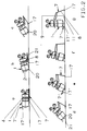
- the discharge body 1 shown in FIG. 1 with a bottom end 2 and a head end 3 is a lead which has a gimbal joint 4 as a suspension which is arranged above the center of gravity S of the discharge body 1.
- the mine consists essentially of a mine body 5 with an explosive charge and a rocket motor 6 as a drive.
- the rocket motor is fired on the basis of sensor signals characteristic of an object to be combated and the mine is transported to a height of approximately 100 to 300 m. The mine then fights the object from this height.
- the suspension in the gimbal joint 4 causes the erected mine to assume a vertical position even on uneven ground, i.e. can be easily transported vertically upwards.
- erecting element 7 Of the five erecting elements, for example, which are evenly distributed over the circumference of the discharge body 1, only one erecting element 7 is shown here for the sake of simplifying the drawing, namely in the right half of the figure in the starting position and in the left half of the figure in the end position. With regard to the representation in the right half of the figure, it should also be pointed out that the ejection body 1 shown here standing upright with the erecting element 7 in the starting position is only an "imaginary" position, since in reality the ejector body 1 with the erecting element 7 would be more or less horizontal in the starting position on the ground.
- the formation of the erecting element 7 can best be seen in the left half of this figure.
- the erecting element 7 has the end link 8 and the intermediate link 9. These two Links are hinged together at pivot point A.
- a web 10 is fastened vertically to the joint 4 and has the pivot point B at its upper end.
- the intermediate member 9 is articulated with its end facing away from the pivot point A.
- the web 10 has the fulcrum C, at which a guide member 11 is articulated at one end. With its other end, the guide member 11 is articulated at the pivot point D of the end member 8.
- the - viewed in the vertical direction - distance between the pivot points A and D is less than the distance between the pivot points B and C, so that there is only a desired approximate parallel guidance of the articulated members.
- the web 10 could of course be omitted if the joint 4 had a correspondingly higher dimension, or the pivot points B and C were arranged, for example, directly on the outer surface of the housing of the discharge body 1.
- the end member 8, the intermediate member 9, the web 10 and the guide member 11 are essentially rigid, rod-shaped, web-like or the like. Elements trained.
- a pyrotechnically actuated force element 12 is provided as the drive element for the erecting elements 7, which is articulated with one end at the pivot point B and with its other end preferably at the diagonally opposite pivot point D.
- the force element 12 has the cylindrical housing 13 and the piston rod 14.
- the piston rod 14 can be pressed out of the cylindrical housing 13 under the action of a pyrotechnic gas generating gas and is articulated with its outer free end at the pivot point D.
- the stop 15 and the stop 16 on the end member 8 are provided in the region of the pivot point A, the stop 16 coming into abutment in the end position.
- the end member 8 has at its end 8 'remote from the pivot point A the foot 17 in the form of a support plate.
- the links 8, 9 and 11 and the force element 12 with the piston rod 14 still inside the housing 13 are folded up to the discharge body 1 and held in this starting position by means of a tether strap 18.
- the discharge body is stored and transported. Even after its distribution, it lies on the ground for a certain time.
- the tether 18 is released, so that the upright elements 7 can be omitted under the action of drive elements, for example in the pivot points B and C arranged pretensioned torsion springs, finally to those in the left half of the Figure shown end position to be taken.
- the discharge body 1 is then erected in the ambush position in the terrain.
- the arrangement is to be made such that when the intermediate member 9 is folded upward about the pivot point B and the end member 8 is folded downward about the pivot point A, the force element 12 force exerted on the end link 8 generates a torque about the pivot points A and B, which causes the links 8 and 9 to begin to fall apart and finally to bring them into the end position.
- the pivot point D is arranged laterally somewhat further away from the longitudinal axis 19 of the discharge body 1 than the pivot point A in the direction of the spreading movement.
- connection points A, B, C and D connection points of the individual links it is achieved that the foot 17 of the end link 8 is moved slightly further away from the longitudinal axis 19 when spreading than it would be expected according to the length of the intermediate member 9.
- the end member 8, the intermediate member 9 and the guide member 11 are approximately half as long as the discharge body 1 is high, and it is nevertheless achieved with this erecting element 7 that the foot 17 is almost as far from the longitudinal axis 19 how discharge body 1 is high.
- the movement of the links is limited in the end position by the stops 15, 16.
- it can also be provided to design the force element 12 in a known manner so that its piston and thus also its piston rod 14 remain in this after reaching the end position and no longer slip back by the piston in the housing 13 e.g. jammed or enters into a positive connection with this in the end position.
- the force element 12 is preferably provided with a damping device, e.g. provided in the manner of the hydraulic shock absorbers known from motor vehicles, so that the unfolding of the erecting elements 7 is damped in its dynamics and stretched in time.
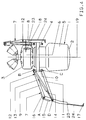
- FIG. 2 shows a successive stages of the positioning process of the discharge body 1 in the diagrams a to g in a schematic representation.
- the meaning of the reference numerals is the same as in FIG. 1.
- erection is explained using only a single erection element 7. Only a further erection element 7 'is indicated with its foot 17', as if it had already been completely eliminated from the start.
- the cardan joint 4 is attached to the ejector body 1 such that the center of gravity of the ejector body 1 is lower than the joint 4 in the upright state. It can be seen that the foot 17 of the end member 8 and the support point 20 of the rounded bottom end 2 of the discharge body 1 on the ground floor 21 remain virtually unchanged during the erection process in the initial phase and the actual span is only achieved towards the end of the erection. From this series it can also be seen that the erection body 1 can be erected in any position in the terrain and the collapsed erection elements 7, 7 'practically do not increase the volume of the ejector body 1.
- FIG. 3 shows a discharge body 1 with erection elements 7 which are varied compared to FIG. 1, with only one erection element 7 of the several again being shown in a very schematic representation in order to simplify the drawing.
- the force element 12 is also omitted in comparison to FIG. 1.
- the upright element 7 is modified in such a way that the pivot point D between the end member 8 and the guide member 11 is no longer rigidly fixed during the erection process, but rather during the spreading of the end member 8 in a longitudinal guide 22 formed on the end member 8 in the direction of the pivot point A. to move until it reaches its predetermined end position D 'in the longitudinal guide 22 and engages in it.
- the longitudinal guide 22 could, for example, also be replaced by an eccentric.
- the end member 8 During the erection of the discharge body 1 from the horizontal, indicated by the line 21 symbolizing the terrain floor, the end member 8 remains practically on the guide member 11 until the pivot point D has reached its end position D 'in the longitudinal guide 22 and engages in it , but the rotational mobility is retained. Up to this point, the discharge body 1 has been angled by the angle ⁇ relative to the ground, symbolized by the line 21 ', erect. The further positioning process then takes place in accordance with FIG. 1.
- the advantage of this embodiment of the upright elements 7 is that the center of gravity of the discharge body 1 can be higher or a smaller torque is required for the uprighting. A similar effect can be achieved if the end member 8 is made very short and is replaced by a telescopic member.
- FIG. 4 A further variant of this is shown in FIG. 4, in which the rigid part of the end members 8 is only about half as long as in FIG. 1 under otherwise unchanged conditions.
- the elastic support element 24 shoots with the foot 17, so that the end member 8 again has the length as in FIG. 1.
- the web-shaped support element 24 is e.g. made of spring steel. This also ensures that the center of gravity of the erecting body 1 can be higher or the torque required to erect it is smaller. Otherwise, the reference numbers have the same meaning as in FIG. 1.
Abstract
Durch mehrgliedrige, ausklappbare Aufrichtelemente (7) läßt sich die Stützweite bei aufrichtbaren Abwurfkörpern (1) vergrößern, das zum Aufrichten erforderliche Drehmoment verringern und die Standfestigkeit erhöhen. Damit der Fuß (17) der Aufrichtelemente (7) auch die gewünschte definierte Bewegung durchführt, ist wenigstens ein Leitglied (11) (z. B. eine Parallelführung) vorhanden. Die vorgenannten Verbesserungen sind praktisch ohne Volumen- oder Gewichtsvergrößerung des Abwurfkörpers (1) erreichbar. <IMAGE>With multi-part, fold-out erection elements (7), the span with erectable discharge bodies (1) can be increased, the torque required for erection reduced and the stability increased. So that the foot (17) of the erecting elements (7) also performs the desired defined movement, there is at least one guide member (11) (e.g. a parallel guide). The aforementioned improvements can be achieved practically without increasing the volume or weight of the discharge body (1). <IMAGE>
Description
Die Erfindung richtet sich auf eine Vorrichtung zur Positionierung eines Abwurfkörpers, insbesondere einer Mine, entsprechend dem Oberbegriff des Patentanspruchs 1.The invention relates to a device for positioning a discharge body, in particular a mine, according to the preamble of patent claim 1.
Eine solche Vorrichtung ist aus der DE 1 800 121 C3 bekannt. Es hat sich gezeigt, daß derart aufgerichtete Abwurfkörper in besonderen Fällen eine zu kleine Standfestigkeit haben können. Auf unebenem Gelände verlegte aufgerichtete Abwurfkörper können durch natürliche (Sturm) oder künstliche (Räummaßnahmen) Ereignisse wieder umgeworfen werden.Such a device is known from DE 1 800 121 C3. It has been shown that ejection bodies erected in this way can have insufficient stability in special cases. Raised throwing bodies placed on uneven terrain can be knocked down again by natural (storm) or artificial (clearing measures) events.
Der Erfindung liegt die Aufgabe zugrunde, die Standfestigkeit eines Abwurfkörpers, insbesondere einer Mine, ohne wesentliche Änderungen an der äußeren Form zu erhöhen, so daß die Lagerung, der Transport und die Verteilung der Abwurfkörper im wesentlichen beibehalten werden können.The invention has for its object to increase the stability of a discharge body, in particular a mine, without significant changes to the outer shape, so that the storage, transport and distribution of the discharge body can be essentially maintained.
Diese Aufgabe wird erfindungsgemäß durch eine Vorrichtung der eingangs genannten Art gelöst, die entsprechend dem Kennzeichen des Patentanspruchs 1 ausgebildet ist. Weitere vorteilhafte Ausgestaltungen sind in den Unteransprüchen angegeben.This object is achieved according to the invention by a device of the type mentioned at the outset, which is designed in accordance with the characterizing part of patent claim 1. Further advantageous refinements are specified in the subclaims.
Kennzeichnend für die erfindungsgemäße Vorrichtung sind die im Vergleich zu den bekannten Positionierungseinrichtungen in definierter Weise vergleichsweise weit vom Abwurfkörper abspreizbaren bzw. ausstellbaren Endglieder der Aufrichtelemente. Ein Aufrichtelement ist aus mindestens zwei beweglich miteinander verbundenen Gliedern zusammengesetzt. Das äußerste Glied, dessen freies Ende zur Abstützung auf dem Geländeboden dient, wird als Endglied bezeichnet, die übrigen Glieder des Aufrichtelementes als Zwischenglieder. Die Bewegung des Endgliedes, die wegen der Beweglichkeit der Glieder untereinander zunächst unbestimmt wäre, ist durch ein oder mehrere Leitglieder in definierter Weise festgelegt. Durch die Leitglieder ist für jeden Punkt des Aufrichtelementes, insbesondere auch für das freie Ende des Endgliedes, ähnlich wie bei dem bekannten eingliedrigen Aufrichtelement nur eine eindeutig festgelegte Bahn möglich. Damit ist es in vorteilhafter Weise möglich, daß die Aufrichtelemente nach Beendigung des Abspreizvorganges, d.h. in der Endposition, in der "richtigen" Stellung und Entfernung vom Abwurfkörper sich auf dem Geländeboden abstützen. Zur Vergrößerung der Auflagefläche der Endglieder sind diese dabei bevorzugt an ihrem freien Ende mit einem Fuß, z.B. in Form einer Stützplatte, versehen.Characteristic of the device according to the invention are the end members of the erecting elements that can be spread apart or extended comparatively far from the discharge body in a defined manner in comparison to the known positioning devices. An erecting element is composed of at least two members which are movably connected to one another. The outermost link, the free end of which is used for support on the ground, is referred to as the end link, the remaining links of the erecting element as intermediate links. The movement of the end link, which would initially be undetermined due to the mobility of the links with one another, is by one or several guides defined in a defined manner. By means of the guide members, only a clearly defined path is possible for each point of the erecting element, in particular also for the free end of the end member, similar to the known single-member erecting element. It is thus advantageously possible for the erecting elements to be supported on the ground floor after the spreading operation has ended, ie in the end position, in the "correct" position and distance from the discharge body. To enlarge the contact area of the end members, they are preferably provided with a foot at their free end, for example in the form of a support plate.
Die Aufrichtelemente können in verschiedener Art ausgeführt sein, wobei die Leitglieder von der Nürnberger Schere oder der Parallelführung her bekannt sind. Zwischenglied und Leitglied sind bei diesen speziellen Ausführungen in ihrer Funktion nicht zu unterscheiden. Die Glieder der Aufrichtelemente, insbesondere auch das Endglied, erstrecken sich im zusammengelegten Zustand, d.h. in der Ausgangsposition der Aufrichtelemente parallel oder annähernd parallel zur im wesentlichen zylindrischen Mantelfläche des Abwurfkörpers. Besonders bevorzugt sind Aufrichtelemente mit nur einem Zwischenglied und einem Leitglied zusätzlich zu dem Endglied. Dabei ist weiterhin bevorzugt eine nur näherungsweise Parallelführung des Endgliedes mittels des Leitgliedes, derart, daß das Endglied während des Abspreizvorganges zusätzlich noch schräg nach außen verschwenkt wird, so daß in der Endposition die freien Enden der Endglieder der verschiedenen Aufrichtelemente noch weiter vom Abwurfkörper entfernt sind als es bei einer Parallelführung der Fall wäre.The erecting elements can be designed in various ways, the guide members being known from the Nuremberg scissors or the parallel guide. The intermediate link and guide link cannot be distinguished in their function in these special versions. The links of the erecting elements, in particular also the end link, extend in the collapsed state, i.e. in the starting position of the erecting elements parallel or approximately parallel to the essentially cylindrical outer surface of the discharge body. Erecting elements with only one intermediate link and one guide link in addition to the end link are particularly preferred. It is further preferred that the end member is guided only approximately in parallel by means of the guide member, such that the end member is additionally pivoted obliquely outwards during the spreading operation, so that in the end position the free ends of the end members of the various erecting elements are further away from the discharge body than it would be the case with parallel guidance.
Die maximale Länge der Glieder eines Aufrichtelementes ist durch die Höhe des Abwurfkörpers und die Art der Anlenkung der Aufrichtelemente an diesem bestimmt. Wenn die Aufrichtelemente im Bereich des bodenseitigen Endes des Abwurfkörpers an diesem angelenkt sind, ist es bei einem zweigliedrigen erfindungsgemäßen Aufrechtelement mit einem die maximale Länge ausnutzenden Zwischenglied und einem zusätzlich schräg ausstellbaren Endglied möglich, daß die Endglieder in ihrer Endposition mit ihrem freien Ende nahezu um die zweifache Höhe des Abwurfkörpers von dessen Mantel seitlich entfernt sind. Ist die Anlenkung der bevorzugt zweigliedrigen Aufrichtelemente etwa in der Mitte des Abwurfkörpers vorgesehen, sind die Glieder des Aufrichtelementes entsprechend kürzer. Der Vorteil dieser "höheren" Anlenkung ist jedoch eine Erhöhung der Standsicherheit, d.h. zum Umkippen des aufgerichteten Abwurfkörpers ist eine höhere seitliche Krafteinwirkung erforderlich.The maximum length of the links of an erecting element is determined by the height of the discharge body and the type of articulation of the erecting elements on it. If the erecting elements are articulated on the discharge body in the region of the bottom end of the discharge body, it is a two-part structure according to the invention Upright element with an intermediate member that takes advantage of the maximum length and an additionally obliquely extendable end member possible that the end members in their end position with their free end are almost laterally removed from the jacket of its shell by twice the height. If the articulation of the preferably two-part erection elements is provided approximately in the middle of the discharge body, the links of the erection element are correspondingly shorter. The advantage of this "higher" articulation, however, is an increase in stability, ie a higher lateral force is required to tip the erected ejection body.
Die Anlenkung der Aufrichtelemente am Abwurfkörper erfolgt vorzugsweise über ein kardanisches Gelenk, in dem der Abwurfkörper derart aufgehängt ist, das er sich nach dem Aufrichten auch bei unebenem Geländeboden selbstätig senkrecht ausrichtet. Die Länge des Endgliedes ist grundsätzlich so zu bemessen, daß dessen freies Ende sich in der Ausgangsposition, d.h. im zusammengelegten Zustand der Aufrichtelemente - betrachtet bei aufrecht angeordnetem Abwurfkörper - oberhalb von dessen Schwerpunkt befindet. Je weiter sich dabei das freie Ende vom Schwerpunkt entfernt befindet, um so geringer ist das für das Aufrichten des Abwurfkörpers erforderliche Drehmoment. Um dennoch eine möglichst große Stützweite, d.h. einen möglichst großen seitlichen Abstand des freien Endes des Endgliedes vom Abwurfkörper in der Endposition zu erreichen, kann weiterhin bevorzugt vorgesehen werden, die Endglieder durch elastische stabförmige Stützelemente aus z.B. Federstahl zu verlängern. Damit wird erreicht, daß beim Beginn des Aufrichtens des Abwurfkörpers zunächst nur der starre Bereich des Endgliedes wirksam wird, das Endglied sich also mit dem Ende dieses starren Bereiches, der sich "oberhalb" des Schwerpunktes des Ahwurfkörpers befindet, auf dem Geländeboden abstützt und die elastisch verformbare Verlängerung des Endgliedes noch auf dem Geländeboden mehr oder weniger flach aufliegt. Mit dem Fortschreiten des Aufrichtens des Abwurfkörpers nimmt dann auch die federelastische Verlängerung zunehmend eine gestreckte Form an, so daß der eigentliche Abstützpunkt des Endgliedes immer weiter zu dessen tatsächlichen freien Ende hin wandert. In der Endposition hat die Verlängerung dann wieder wie in der Ausgangsposition eine gestreckte Form angenommen.The erection elements are preferably articulated on the ejection body via a cardan joint in which the ejection body is suspended in such a way that it automatically aligns itself vertically after erection even on uneven ground. The length of the end member is generally to be dimensioned such that its free end is in the starting position, ie in the collapsed state of the erecting elements - when viewed with the ejection body upright - above its center of gravity. The farther away the free end is from the center of gravity, the lower the torque required to raise the discharge body. In order nevertheless to achieve the largest possible span, ie the greatest possible lateral distance of the free end of the end member from the ejection body in the end position, it can further be preferred to extend the end members by means of elastic rod-shaped support elements made of, for example, spring steel. This ensures that only the rigid area of the end member is effective at the beginning of the erection of the discharge body, the end member is thus with the end of this rigid area, which is "above" the center of gravity of the launching body, supported on the ground and the elastic deformable extension of the end member still lies more or less flat on the ground. As the erection body progresses the resilient extension then also assumes an elongated shape, so that the actual support point of the end link moves further and further towards its actual free end. In the end position, the extension then again has an elongated shape as in the starting position.
Die Begrenzung der Abspreizbewegung des Endgliedes in seiner Endposition kann beispielsweise erfolgen, indem in dieser Position eine formschlüssige Verriegelung (Verrastung) zwischen dem Endglied und dem Zwischenglied im Bereich des gemeinsamen Drehgelenkes erfolgt. Eine andere Möglichkeit besteht in der Anordnung von Anschlägen an diesen beiden Gliedern im Bereich des gemeinsamen Drehpunktes.The spreading movement of the end link in its end position can be limited, for example, by positive locking (latching) between the end link and the intermediate link in the region of the common swivel joint in this position. Another possibility is to arrange stops on these two links in the area of the common pivot point.
Um die Aufrichtelemente nach Ablauf einer vorgegebenen Zeitspanne nach dem Auftreffen des Abwurfkörpers auf dem Geländeboden aus ihrer Ausgangsposition in ihre Endposition zu überführen, d.h. auszustellen, sind Antriebselemente erforderlich. Dies können vorgespannte Federn, insbesondere Dreh- oder Torsionsfedern, sein, die in wenigstens einem Drehpunkt ein entsprechendes Drehmoment auf das jeweilige Glied bzw. die jeweiligen Glieder ausüben. Zusätzlich oder statt dessen können aber auch pyrotechnisch betätigte Kraftelemente vorgesehen sein. Diese sind dann vorzugswiese zwischen den sich diagonal gegenüberliegenden Drehpunkten der bevorzugten näherungsweise Parallelführung der Glieder angeordnet. Das Kraftelement ist dabei bevorzugt so ausgebildet, daß seine Kolbenstange ausgefahren wird und die Druckgasbeaufschlagung auf der von der Kolbenstange abgewandten Seite des Kolbens erfolgt, um eine möglichst kleine Baugröße des Kraftelementes zu erreichen. Statt jedem einzelnen Kraftelement eine separate druckgaserzeugende pyrotechnische Ladung zuzuordnen, kann auch eine zentrale Treibgasversorgung mittels eines entsprechenden größeren Gasgenerators vorgesehen werden.In order to move the erecting elements from their starting position to their end position after a predetermined time period after the impact of the ejection body on the ground, drive elements are required. These can be prestressed springs, in particular torsion or torsion springs, which exert a corresponding torque on the respective link or links in at least one pivot point. In addition or instead, pyrotechnically operated force elements can also be provided. These are then preferably arranged between the diagonally opposite pivot points of the preferred approximately parallel guidance of the links. The force element is preferably designed so that its piston rod is extended and the pressurized gas is applied to the side of the piston facing away from the piston rod in order to achieve the smallest possible size of the force element. Instead of assigning a separate compressed gas-generating pyrotechnic charge to each individual force element, a central propellant gas supply can also be provided by means of a correspondingly larger gas generator.
In einer weiteren bevorzugten Ausführungsform ist jedem Aufrichtelement eine Dämpfungseinrichtung zugeordnet, um den Aufrichtvorgang langsamer ablaufen zu lassen und damit dynamische Beschleunigungs- und Verzögerungskräfte entsprechend klein zu halten. Besonders bevorzugt ist dabei die Kombination der Dämpfungseinrichtung mit den vorgenannten Kraftelementen, indem deren kolbenstangenseitiger Hohlraum im Zylinder ein Fluid, z.B. Öl, enthält, das beim Verschieben des Kolbens und dem damit verbundenen Ausfahren der Kolbenstange aus dem zylindrischen Gehäuse des Kraftelementes nach dem von hydraulischen Stoßdämpfern her bekannten Prinzip verdrängbar ist.In a further preferred embodiment, a damping device is assigned to each erection element in order to make the erection process run more slowly and thus to keep dynamic acceleration and deceleration forces correspondingly small. The combination of the damping device with the aforementioned force elements is particularly preferred, in that their piston rod-side cavity in the cylinder contains a fluid, e.g. Contains oil, which is displaceable when the piston is displaced and the associated extension of the piston rod from the cylindrical housing of the force element according to the principle known from hydraulic shock absorbers.
Die besonders bevorzugte erfindungsgemäße Vorrichtung hat insbesondere die Vorteile, daß sie in vergleichsweise leichter Bauweise ausgeführt werden kann, da durch das langsame gedämpfte Aufrichten nur geringe dynamische Kräfte auftreten. Durch den Einsatz von insbesondere pyrotechnisch betätigten Kraftelementen, vorzugsweise mit aus dem zylindrischen Gehäuse herausdrückbarer Kolbenstange, können hohe Aufrichtkräfte aufgebracht werden. Das Aufrichten ist auch bei einem Abwurfkörper mit vergleichsweise hohem Schwerpunkt ohne weiteres möglich, wobei sich dieser bei einer Aufhängung im kardanischen Gelenk nach dem Aufrichten zusätzlich noch selbstätig in eine exakt vertikale Position ausrichtet. Durch die große Stützweite bei aufgerichtetem Abwurfkörper wird eine hohe Standsicherheit erreicht, wobei dennoch die Glieder der Aufrichtelemente vergleichsweise kurz sein können und dementsprechend wenig Staulänge benötigt wird.The particularly preferred device according to the invention has the particular advantages that it can be carried out in a comparatively light construction, since only slow dynamic forces occur due to the slow, damped erection. By using in particular pyrotechnically actuated force elements, preferably with a piston rod that can be pushed out of the cylindrical housing, high uprighting forces can be applied. Raising is also easily possible even with a discharge body with a comparatively high center of gravity, which, in the case of a suspension in the gimbal joint, also automatically aligns itself into a precisely vertical position after the raising. Due to the large support width when the ejection body is erected, a high level of stability is achieved, but the links of the erecting elements can nevertheless be comparatively short and, accordingly, little stowage length is required.
Die erfindungsgemäße Vorrichtung ist in der Zeichnung in einem Ausführungsbeispiel schematisch dargestellt und wird anhand dessen nachstehend noch weiter erläutert. Es zeigen
- Fig. 1
- die Seitenansicht eines Abwurfkörpers, wobei die linke Hälfte ein Aufrichtelement in der Endposition und die rechte Hälfte ein Aufrichtelement in der Ausgangsposition zeigt,
- Fig. 2
- die Simulation des Aufrichtvorganges mit einem Aufrichtelement,
- Fig. 3
- die Seitenansicht eines Abwurfkörpers mit einem gegenüber Fig. 1 variierten Aufrichtelement und
- Fig. 4
- die Seitenansicht eines Abwurfkörpers mit einer weiteren Variante eines Aufrichtelementes.
- Fig. 1
- the side view of a discharge body, the left half showing an erection element in the end position and the right half an erection element in the starting position,
- Fig. 2
- the simulation of the erection process with an erection element,
- Fig. 3
- the side view of a discharge body with an uprighting element varied compared to FIG. 1 and
- Fig. 4
- the side view of a discharge body with a further variant of an erecting element.
Bei dem in Figur 1 gezeigten Abwurfkörper 1 mit einem bodenseitigen Ende 2 und einem kopfseitigen Ende 3 handelt es sich um eine Mine, die als Aufhängung ein kardanisches Gelenk 4 aufweist, das oberhalb des Schwerpunktes S des Abwurfkörpers 1 angeordnet ist. Die Mine besteht im wesentlichen aus einem Minenkörper 5 mit einer Sprengladung und einem Raketenmotor 6 als Antrieb. Aufgrund von für ein zu bekämpfendes Objekt charakteristischen Sensorsignalen wird der Raketenmotor gezündet und die Mine in eine Höhe von etwa 100 bis 300 m transportiert. Die Mine bekämpft dann aus dieser Höhe das Objekt. Die Aufhängung in dem kardanischen Gelenk 4 bewirkt, daß die aufgerichtete Mine auch bei einem unebenen Geländeboden eine vertikale Position einnimmt, d.h. einwandfrei vertikal nach oben transportierbar ist.The discharge body 1 shown in FIG. 1 with a
Von den beispielsweise fünf Aufrichtelementen, die gleichmäßig über den Umfang des Abwurfkörpers 1 verteilt angeordnet sind, ist hier zur Vereinfachung der zeichnerischen Darstellung nur ein Aufrichtelement 7 gezeigt, und zwar in der rechten Hälfte der Figur in der Ausgangsposition und in der linken Hälfte der Figur in der Endposition. Bezüglich der Darstellung in der rechten Hälfte der Figur ist noch darauf hinzuweisen, daß es sich bei dem hier aufrecht stehend gezeigten Abwurfkörper 1 mit dem Aufrichtelement 7 in der Ausgangsposition nur um eine "gedachte" Stellung handelt, da in Wirklichkeit der Abwurfkörper 1 mit dem Aufrichtelement 7 in der Ausgangsposition auf dem Geländeboden mehr oder weniger waagerecht liegen würde.Of the five erecting elements, for example, which are evenly distributed over the circumference of the discharge body 1, only one erecting
Die Ausbildung des Aufrichtelementes 7 ist am besten in der linken Hälfte dieser Figur zu erkennen. Das Aufrichtelement 7 weist das Endglied 8 und das Zwischenglied 9 auf. Diese beiden Glieder sind am Drehpunkt A gelenkig miteinander verbunden. Am Gelenk 4 ist vertikal ein Steg 10 befestigt, der an seinem oberen Ende den Drehpunkt B aufweist. An diesem ist das Zwischenglied 9 mit seinem vom Drehpunkt A abgewandten Ende angelenkt. An seinem unteren Ende weist der Steg 10 den Drehpunkt C auf, an dem ein Leitglied 11 mit seinem einem Ende angelenkt ist. Mit seinem anderen Ende ist das Leitglied 11 am Drehpunkt D des Endgliedes 8 angelenkt. Der - in vertikaler Richtung betrachtet - Abstand zwischen den Drehpunkten A und D ist dabei geringer als der Abstand zwischen den Drehpunkten B und C, so daß hier nur eine gewollte angenäherte Parallelführung der gelenkig miteinander verbundenen Glieder vorliegt. Der Steg 10 könnte natürlich entfallen, wenn das Gelenk 4 eine entsprechend höhere Abmessung hätte, oder die Drehpunkte B und C z.B. direkt an der Mantelfläche des Gehäuses des Abwurfkörpers 1 angeordnet wären. Das Endglied 8, das Zwischenglied 9, der Steg 10 und das Leitglied 11 sind dabei als in sich starre im wesentlichen stab-, stangen-, stegförmige o.dgl. Elemente ausgebildet.The formation of the erecting
Als Antriebselement für die Aufrichtelemente 7 ist ein pyrotechnisch betätigtes Kraftelement 12 vorgesehen, das mit seinem einem Ende am Drehpunkt B und mit seinem anderen Ende bevorzugt am diagonal gegenüberliegenden Drehpunkt D angelenkt ist. Das Kraftelement 12 weist das zylindrische Gehäuse 13 sowie die Kolbenstange 14 auf. Die Kolbenstange 14 ist unter der Wirkung eines druckgaserzeugenden pyrotechnischen Satzes aus dem zylindrischen Gehäuse 13 herausdrückbar und mit ihrem äußeren freien Ende am Drehpunkt D angelenkt. Zur Begrenzung der Abspreizbewegung des Endgliedes 8 in der gezeigten Endposition sind im Bereich des Drehpunktes A am Endglied 8 der Anschlag 15 und am Zwischenglied 9 der Anschlag 16 vorgesehen, die in der Endposition zur Anlage aneinander kommen. Das Endglied 8 weist an seinem vom Drehpunkt A abgewandten Ende 8' den Fuß 17 in Form einer Stützplatte auf.A pyrotechnically actuated
In der rechten Hälfte der Figur sind die Glieder 8, 9 und 11 sowie das Kraftelement 12 mit noch innerhalb des Gehäuses 13 befindlicher Kolbenstange 14 an den Abwurfkörper 1 herangeklappt und in dieser Ausgangsposition mittels eines Fesselbandes 18 gehalten. In diesem Zustand wird der Abwurfköper gelagert und transportiert. Er liegt auch noch so nach seiner Verteilung für eine gewisse Zeit auf dem Geländeboden. Nach einer vorbestimmten Zeit nach dem Auftreffen auf dem Geländeboden wird das Fesselband 18 freigegeben, so daß sich die Aufrechtelemente 7 unter der Wirkung von Antriebselementen, beispielsweise in den Drehpunkten B und C angeordneten vorgestpannten Drehfedern, entfallten können, um schließlich die in der linken Hälfte der Figur gezeigte Endposition einzunehmen. Der Abwurfkörper 1 befindet sich dann aufgerichtet in der Lauerstellung im Gelände.In the right half of the figure, the
Sofern entsprechend Fig. 1 als Antriebselement nur das Kraftelement 12 vorgesehen ist, ist die Anordnung so zu treffen, daß bei um den Drehpunkt B nach "oben" geklapptem Zwischenglied 9 und um den Drehpunkt A nach "unten" geklapptem Endglied 8 die vom Kraftelement 12 auf das Endglied 8 ausgeübte Kraft ein Drehmoment um die Drehpunkte A und B erzeugt, welches den Beginn des Auseinanderfalltens der Glieder 8 und 9 und schließlich deren Überführung in die Endposition bewirkt. Dazu ist in der Ausgangsposition der Drehpunkt D gegenüber dem Drehpunkt A in Richtung der Abspreizbewegung seitlich etwas weiter entfernt von der Längsachse 19 des Abwurfkörpers 1 angeordnet.If only the
Bei der vorstehend bereits erläuterten Funktionsauslösung nach Freigabe des Fesselbandes 18 und Initiierung der druckgaserzeugenden pyrotechnischen Ladung im Kraftelement 12 wird dessen Kolben beaufschlagt und damit die Kolbenstange 14, vorzugsweise gedämpft, aus dem zylindrischen Gehäuse 13 hinausgedrückt, wodurch das Endglied 8 des Aufrichtelementes 7 in der Anfangsphase der Abspreizbewegung im wesentlichen parallel zur Längsachse 19 seitlich nach außen bewegt wird. Das Leitglied 11 steuert als angenäherte Parallelführung diese Bewegung des Endgliedes 8. Durch die vorstehend beschriebene geeignete Wahl der Verbindungspunkte (Drehpunkte A, B, C und D) der einzelnen Glieder wird erreicht, daß der Fuß 17 des Endgliedes 8 beim Abspreizen etwas weiter von der Längsachse 19 weg nach außen bewegt wird als es nach der Länge des Zwischengliedes 9 zu erwarten wäre. In der gezeigten Ausführungsform sind das Endglied 8, das Zwischenglied 9 sowie das Leitglied 11 etwa halb so lang wie der Abwurfkörper 1 hoch ist, und es wird dennoch bei diesem Aufrichtelement 7 erreicht, daß der Fuß 17 fast so weit von der Längsachse 19 entfernt ist wie Abwurfkörper 1 hoch ist.In the case of the function triggering already explained above after release of the
Die Bewegung der Glieder ist in der Endposition durch die Anschläge 15, 16 begrenzt. Zusätzlich oder statt dessen kann aber auch vorgesehen werden, das Kraftelement 12 in bekannter Weise so auszubilden, daß sein Kolben und damit auch seine Kolbenstange 14 nach Erreichen der Endposition in dieser verbleibt und nicht mehr zurückrutscht, indem sich der Kolben in dem Gehäuse 13 z.B. verklemmt oder mit diesem in der Endposition eine Formschlußverbindung eingeht. Außerdem ist das Kraftelement 12 bevorzugt mit einer Dämpfungseinrichtung z.B. nach Art der von Kraftfahrzeugen her bekannten hydraulischen Stoßdämpfer versehen, so daß das Auseinanderfalten der Aufrichtelemente 7 in seiner Dynamik gedämpft und zeitich gedehnt ist. Durch alle diese Maßnahmen können die Aufrichtelemente 7 relativ leicht gebaut werden und es wird eine erhebliche Verbesserung der Standfestigkeit des Abwurfkörpers 1 erreicht, ohne daß dazu dessen Gewicht erhöht werden müßte.The movement of the links is limited in the end position by the
Fig. 2 zeigt in den Bildern a bis g verschiedene aufeinander folgende Stadien des Positionierungsvorganges des Abwurfkörpers 1 in schematischer Darstellung. Die Bedeutung der Bezugszeichen ist die gleiche wie in Fig. 1. Auch hier wird aus zeichentechnischen Gründen das Aufrichten nur anhand eines einzigen Aufrichtelementes 7 erläutert. Es ist nur noch ein weiteres Aufrichtelement 7' mit seinem Fuß 17' angedeutet, und zwar so, als ob es von Beginn an bereits voll entfalltet wäre.2 shows a successive stages of the positioning process of the discharge body 1 in the diagrams a to g in a schematic representation. The meaning of the reference numerals is the same as in FIG. 1. Here, too, for reasons of drawing technology, erection is explained using only a
Das kardanische Gelenk 4 ist derart am Abwurfkörper 1 angebracht, daß der Schwerpunkt des Abwurfkörpers 1 im aufrechten Zustand tiefer als das Gelenk 4 liegt. Man erkennt, daß der Fuß 17 des Endgliedes 8 und der Auflagepunkt 20 des abgerundeten bodenseitigen Endes 2 des Abwurfkörpers 1 auf dem Geländeboden 21 während des Aufrichtvorgangs in der Anfangsphase nahezu örtlich unverändert bleiben und erst gegen Ende des Aufrichtens die eigentliche Stützweite erzielt wird. Auch aus dieser Reihe ist erkennbar, daß das Aufrichten des Abwurfkörpers 1 in jeder Lage im Gelände möglich ist und die zusammengefallteten Aufrichtelemente 7, 7' das Volumen des Abwurfkörpers 1 praktisch nicht vergrößern.The
In Fig. 3 ist ein Abwurfkörper 1 mit gegenüber Fig. 1 variierten Aufrichtelementen 7 gezeigt, wobei zur Vereinfachung der zeichnerischen Darstellung wiederum nur ein einziges Aufrichtelement 7 von den mehreren in sehr schematischer Darstellung gezeigt ist. Zur weiteren Vereinfachung ist dabei auch im Vergleich zur Fig. 1 das Kraftelement 12 weggelassen. Das Aufrechtelement 7 ist dahingehend modifiziert, daß der Drehpunkt D zwischen dem Endglied 8 und dem Leitglied 11 nicht mehr während des Aufrichtvorgangs starr fixiert ist, sondern sich während des Abspreizens des Endgliedes 8 in einer am Endglied 8 ausgebildeten Längsführung 22 in Richtung auf den Drehpunkt A zu verschiebt, bis er in der Längsführung 22 seine vorgegebene Endposition D' erreicht und in dieser einrastet. Die Längsführung 22 könnte beispielsweise auch durch einen Exzenter ersetzt werden. Während des Aufrichtens des Abwurfkörpers 1 aus der Horizontalen, angedeutet durch die den Geländeboden symbolisierende Linie 21, bleibt hierbei das Endglied 8 am Leitglied 11 praktisch so lange angelegt, bis der Drehpunkt D seine Endposition D' in der Längsführung 22 erreicht hat und in dieser einrastet, wobei die Drehbeweglichkeit jedoch erhalten bleibt. Der Abwurfkörper 1 hat sich bis zu diesem Zeitpunkt um den Winkel α gegenüber dem Geländeboden, symbolisiert durch die Linie 21', aufgerichtet. Der weitere Positionierungsvorgang erfolgt dann entsprechend der Fig. 1. Der Vorteil dieser Ausführungsform der Aufrechtelemente 7 besteht darin, daß der Schwerpunkt des Abwurfkörpers 1 höher liegen kann oder ein kleineres Drehmoment zum Aufrichten benötigt wird. Eine ähnliche Wirkung ist erzielbar, wenn das Endglied 8 sehr kurz ausgeführt und durch ein Teleskopglied ersetzt wird.FIG. 3 shows a discharge body 1 with
Eine weitere Variante hierzu ist in Fig. 4 gezeigt, bei welcher der starre Teil der Endglieder 8 unter sonst unveränderten Bedingungen nur etwa halb so lang wie in Fig. 1 ist. An das so entstandene Ende 23 des Endgliedes 8 schießt sich das elastische Stützelement 24 mit dem Fuß 17 an, so daß das Endglied 8 insgesamt wieder die Länge wie in Fig. 1 hat. Das stegförmige Stützelement 24 ist z.B. aus Federstahl hergestellt. Auch hiermit wird erreicht, daß der Schwerpunkt des Aufrichtkörpers 1 höher liegen kann oder das zu dessen Aufrichten erforderliche Drehmoment kleiner ist. Im übrigen haben die Bezugsziffern die gleiche Bedeutung wie in Fig. 1.A further variant of this is shown in FIG. 4, in which the rigid part of the
Claims (16)
Applications Claiming Priority (2)
| Application Number | Priority Date | Filing Date | Title |
|---|---|---|---|
| DE4037173 | 1990-11-22 | ||
| DE4037173A DE4037173A1 (en) | 1990-11-22 | 1990-11-22 | Ejection body with improved sitting behavior |
Publications (3)
| Publication Number | Publication Date |
|---|---|
| EP0487021A2 true EP0487021A2 (en) | 1992-05-27 |
| EP0487021A3 EP0487021A3 (en) | 1993-03-24 |
| EP0487021B1 EP0487021B1 (en) | 1996-09-04 |
Family
ID=6418734
Family Applications (1)
| Application Number | Title | Priority Date | Filing Date |
|---|---|---|---|
| EP91119706A Expired - Lifetime EP0487021B1 (en) | 1990-11-22 | 1991-11-19 | Erecting device for air-dropped body |
Country Status (4)
| Country | Link |
|---|---|
| US (1) | US5237926A (en) |
| EP (1) | EP0487021B1 (en) |
| JP (1) | JPH04270900A (en) |
| DE (2) | DE4037173A1 (en) |
Cited By (2)
| Publication number | Priority date | Publication date | Assignee | Title |
|---|---|---|---|---|
| GB2259970A (en) * | 1991-09-27 | 1993-03-31 | Samir Abed Issa Albasri | Oral communication device |
| US6955125B1 (en) * | 2002-02-26 | 2005-10-18 | The United States Of America As Represented By The Secretary Of The Army | Practice projectile with smoke signature |
Families Citing this family (1)
| Publication number | Priority date | Publication date | Assignee | Title |
|---|---|---|---|---|
| CN115282533B (en) * | 2022-06-30 | 2023-06-27 | 温州温工工程机械有限公司 | Electromagnetic ejection fire extinguishing bomb for high-rise fire extinguishment |
Citations (3)
| Publication number | Priority date | Publication date | Assignee | Title |
|---|---|---|---|---|
| EP0296382A2 (en) * | 1987-06-04 | 1988-12-28 | Dynamit Nobel Aktiengesellschaft | Self-erecting mine |
| EP0423631A2 (en) * | 1989-10-20 | 1991-04-24 | Dynamit Nobel Aktiengesellschaft | Self-adjusting mine |
| EP0461446A1 (en) * | 1990-06-15 | 1991-12-18 | Dynamit Nobel Aktiengesellschaft | Mine for defending a zone with increased field of activity |
Family Cites Families (10)
| Publication number | Priority date | Publication date | Assignee | Title |
|---|---|---|---|---|
| US952805A (en) * | 1909-10-19 | 1910-03-22 | James C Hall | Rocket-head grapple. |
| US1330079A (en) * | 1919-08-21 | 1920-02-10 | Kobuchi Luis | Projectile |
| FR2071271A5 (en) * | 1969-12-23 | 1971-09-17 | Serat | Parachute anti-tank mine - with braking surfaces |
| DE3127071C2 (en) * | 1981-07-09 | 1985-06-27 | Messerschmitt-Bölkow-Blohm GmbH, 8000 München | Ejector body |
| DE3509281A1 (en) * | 1985-03-15 | 1986-09-25 | Messerschmitt-Bölkow-Blohm GmbH, 8012 Ottobrunn | Device for aiming an active body |
| DE3710989A1 (en) * | 1987-04-01 | 1988-10-27 | Dornier Gmbh | AIR RELAXING MINE |
| DE3817265A1 (en) * | 1988-05-20 | 1989-11-30 | Diehl Gmbh & Co | STAND DEVICE FOR A MINE |
| GB2227081B (en) * | 1988-12-24 | 1992-11-11 | Dynamit Nobel Ag | Mine |
| FR2646232B1 (en) * | 1989-04-25 | 1994-03-11 | Thomson Brandt Armements | AUTOMATED WEAPON SYSTEM FOR ZONE DEFENSE |
| US5069136A (en) * | 1990-09-14 | 1991-12-03 | Honeywell Inc. | Two-stage release mechanism and method for self-righting a load |
-
1990
- 1990-11-22 DE DE4037173A patent/DE4037173A1/en not_active Withdrawn
-
1991
- 1991-11-18 US US07/793,572 patent/US5237926A/en not_active Expired - Fee Related
- 1991-11-19 DE DE59108140T patent/DE59108140D1/en not_active Expired - Fee Related
- 1991-11-19 EP EP91119706A patent/EP0487021B1/en not_active Expired - Lifetime
- 1991-11-21 JP JP3306101A patent/JPH04270900A/en active Pending
Patent Citations (3)
| Publication number | Priority date | Publication date | Assignee | Title |
|---|---|---|---|---|
| EP0296382A2 (en) * | 1987-06-04 | 1988-12-28 | Dynamit Nobel Aktiengesellschaft | Self-erecting mine |
| EP0423631A2 (en) * | 1989-10-20 | 1991-04-24 | Dynamit Nobel Aktiengesellschaft | Self-adjusting mine |
| EP0461446A1 (en) * | 1990-06-15 | 1991-12-18 | Dynamit Nobel Aktiengesellschaft | Mine for defending a zone with increased field of activity |
Cited By (2)
| Publication number | Priority date | Publication date | Assignee | Title |
|---|---|---|---|---|
| GB2259970A (en) * | 1991-09-27 | 1993-03-31 | Samir Abed Issa Albasri | Oral communication device |
| US6955125B1 (en) * | 2002-02-26 | 2005-10-18 | The United States Of America As Represented By The Secretary Of The Army | Practice projectile with smoke signature |
Also Published As
| Publication number | Publication date |
|---|---|
| EP0487021B1 (en) | 1996-09-04 |
| DE4037173A1 (en) | 1992-05-27 |
| US5237926A (en) | 1993-08-24 |
| DE59108140D1 (en) | 1996-10-10 |
| JPH04270900A (en) | 1992-09-28 |
| EP0487021A3 (en) | 1993-03-24 |
Similar Documents
| Publication | Publication Date | Title |
|---|---|---|
| DE1800121C3 (en) | Device for the defined positioning of drop bodies, in particular explosive charges | |
| DE2635213C3 (en) | Device for erecting a net barrier for catching aircraft | |
| DE2806081A1 (en) | Wind turbine mast structure - has assembly stay on the side, with hydraulic tensioner enabling raising and lowering | |
| DE2318307C2 (en) | Missile ejector head | |
| EP0487021B1 (en) | Erecting device for air-dropped body | |
| DE1553980C3 (en) | Device for adjusting the firing range of rocket projectiles | |
| DE2826543C2 (en) | ||
| DE1925055C3 (en) | Missile with at least one pivotably mounted guide surface | |
| DE1506101A1 (en) | Device for proper parachute deployment | |
| DE3638976C2 (en) | Erection device | |
| DE2300230C3 (en) | Jumping mine | |
| DE3617566C2 (en) | ||
| EP0461446B1 (en) | Mine for defending a zone with increased field of activity | |
| DE4005404C2 (en) | ||
| DE1131559B (en) | Flying body for practice purposes | |
| DE3917662C2 (en) | mine | |
| DE2448495A1 (en) | ROCKET DRIVE DEVICE | |
| CH616191A5 (en) | Clamping device for an appliance which can be used for sinking rod-shaped elements into the ground | |
| DE2301957A1 (en) | DELAY IGNITER FOR ONE FLOOR | |
| DE1506101C (en) | Pyrotechnic device for the rapid deployment of a parachute | |
| DE2128815C3 (en) | Ignition device for land mines | |
| DE3425065A1 (en) | Collapsible mast, in particular for a mobile antenna, and vehicle equipped with such a mast | |
| EP0443136A1 (en) | Device for adjusting or aligning a mine | |
| DE2709997A1 (en) | Mountain slope avalanche dispersal barrier - uses weighted stakes discharged onto ground from helicopter | |
| DE2257059A1 (en) | DRIVING MACHINE FOR DRIVING DISTANCE IN SOLID STONES |
Legal Events
| Date | Code | Title | Description |
|---|---|---|---|
| PUAI | Public reference made under article 153(3) epc to a published international application that has entered the european phase |
Free format text: ORIGINAL CODE: 0009012 |
|
| AK | Designated contracting states |
Kind code of ref document: A2 Designated state(s): DE FR GB IT NL |
|
| PUAL | Search report despatched |
Free format text: ORIGINAL CODE: 0009013 |
|
| AK | Designated contracting states |
Kind code of ref document: A3 Designated state(s): DE FR GB IT NL |
|
| 17P | Request for examination filed |
Effective date: 19930903 |
|
| 17Q | First examination report despatched |
Effective date: 19950301 |
|
| GRAH | Despatch of communication of intention to grant a patent |
Free format text: ORIGINAL CODE: EPIDOS IGRA |
|
| GRAA | (expected) grant |
Free format text: ORIGINAL CODE: 0009210 |
|
| RAP1 | Party data changed (applicant data changed or rights of an application transferred) |
Owner name: DYNAMIT NOBEL GMBH EXPLOSIVSTOFF- UND SYSTEMTECHNI |
|
| AK | Designated contracting states |
Kind code of ref document: B1 Designated state(s): DE FR GB IT NL |
|
| PG25 | Lapsed in a contracting state [announced via postgrant information from national office to epo] |
Ref country code: IT Free format text: LAPSE BECAUSE OF FAILURE TO SUBMIT A TRANSLATION OF THE DESCRIPTION OR TO PAY THE FEE WITHIN THE PRESCRIBED TIME-LIMIT;WARNING: LAPSES OF ITALIAN PATENTS WITH EFFECTIVE DATE BEFORE 2007 MAY HAVE OCCURRED AT ANY TIME BEFORE 2007. THE CORRECT EFFECTIVE DATE MAY BE DIFFERENT FROM THE ONE RECORDED. Effective date: 19960904 Ref country code: NL Free format text: LAPSE BECAUSE OF FAILURE TO SUBMIT A TRANSLATION OF THE DESCRIPTION OR TO PAY THE FEE WITHIN THE PRESCRIBED TIME-LIMIT Effective date: 19960904 Ref country code: GB Effective date: 19960904 |
|
| ET | Fr: translation filed | ||
| REF | Corresponds to: |
Ref document number: 59108140 Country of ref document: DE Date of ref document: 19961010 |
|
| PGFP | Annual fee paid to national office [announced via postgrant information from national office to epo] |
Ref country code: FR Payment date: 19961113 Year of fee payment: 6 |
|
| NLV1 | Nl: lapsed or annulled due to failure to fulfill the requirements of art. 29p and 29m of the patents act | ||
| GBV | Gb: ep patent (uk) treated as always having been void in accordance with gb section 77(7)/1977 [no translation filed] |
Effective date: 19960904 |
|
| PLBE | No opposition filed within time limit |
Free format text: ORIGINAL CODE: 0009261 |
|
| STAA | Information on the status of an ep patent application or granted ep patent |
Free format text: STATUS: NO OPPOSITION FILED WITHIN TIME LIMIT |
|
| PG25 | Lapsed in a contracting state [announced via postgrant information from national office to epo] |
Ref country code: DE Effective date: 19970801 |
|
| 26N | No opposition filed | ||
| PG25 | Lapsed in a contracting state [announced via postgrant information from national office to epo] |
Ref country code: FR Free format text: THE PATENT HAS BEEN ANNULLED BY A DECISION OF A NATIONAL AUTHORITY Effective date: 19971130 |
|
| REG | Reference to a national code |
Ref country code: FR Ref legal event code: ST |