EP0485697B1 - Elastisches Gleitlager - Google Patents
Elastisches Gleitlager Download PDFInfo
- Publication number
- EP0485697B1 EP0485697B1 EP91114067A EP91114067A EP0485697B1 EP 0485697 B1 EP0485697 B1 EP 0485697B1 EP 91114067 A EP91114067 A EP 91114067A EP 91114067 A EP91114067 A EP 91114067A EP 0485697 B1 EP0485697 B1 EP 0485697B1
- Authority
- EP
- European Patent Office
- Prior art keywords
- bush
- axial
- bearing
- sliding layer
- flange
- Prior art date
- Legal status (The legal status is an assumption and is not a legal conclusion. Google has not performed a legal analysis and makes no representation as to the accuracy of the status listed.)
- Expired - Lifetime
Links
- 239000004033 plastic Substances 0.000 claims description 25
- 229920003023 plastic Polymers 0.000 claims description 25
- 239000011324 bead Substances 0.000 claims description 16
- 229920001971 elastomer Polymers 0.000 claims description 9
- 238000007789 sealing Methods 0.000 claims description 7
- 239000000806 elastomer Substances 0.000 claims description 6
- 239000012791 sliding layer Substances 0.000 claims description 5
- 239000000314 lubricant Substances 0.000 claims description 4
- 238000006073 displacement reaction Methods 0.000 claims 1
- 239000010410 layer Substances 0.000 description 12
- 230000015572 biosynthetic process Effects 0.000 description 2
- 239000002184 metal Substances 0.000 description 2
- 230000000149 penetrating effect Effects 0.000 description 2
- 229920001343 polytetrafluoroethylene Polymers 0.000 description 2
- 239000004810 polytetrafluoroethylene Substances 0.000 description 2
- 230000004323 axial length Effects 0.000 description 1
- 239000011248 coating agent Substances 0.000 description 1
- 238000000576 coating method Methods 0.000 description 1
- 239000004519 grease Substances 0.000 description 1
- 238000005461 lubrication Methods 0.000 description 1
- 238000004519 manufacturing process Methods 0.000 description 1
- 239000000463 material Substances 0.000 description 1
- -1 polytetrafluoroethylene Polymers 0.000 description 1
- 239000000565 sealant Substances 0.000 description 1
Images
Classifications
-
- F—MECHANICAL ENGINEERING; LIGHTING; HEATING; WEAPONS; BLASTING
- F16—ENGINEERING ELEMENTS AND UNITS; GENERAL MEASURES FOR PRODUCING AND MAINTAINING EFFECTIVE FUNCTIONING OF MACHINES OR INSTALLATIONS; THERMAL INSULATION IN GENERAL
- F16C—SHAFTS; FLEXIBLE SHAFTS; ELEMENTS OR CRANKSHAFT MECHANISMS; ROTARY BODIES OTHER THAN GEARING ELEMENTS; BEARINGS
- F16C27/00—Elastic or yielding bearings or bearing supports, for exclusively rotary movement
- F16C27/06—Elastic or yielding bearings or bearing supports, for exclusively rotary movement by means of parts of rubber or like materials
-
- F—MECHANICAL ENGINEERING; LIGHTING; HEATING; WEAPONS; BLASTING
- F16—ENGINEERING ELEMENTS AND UNITS; GENERAL MEASURES FOR PRODUCING AND MAINTAINING EFFECTIVE FUNCTIONING OF MACHINES OR INSTALLATIONS; THERMAL INSULATION IN GENERAL
- F16F—SPRINGS; SHOCK-ABSORBERS; MEANS FOR DAMPING VIBRATION
- F16F1/00—Springs
- F16F1/36—Springs made of rubber or other material having high internal friction, e.g. thermoplastic elastomers
- F16F1/38—Springs made of rubber or other material having high internal friction, e.g. thermoplastic elastomers with a sleeve of elastic material between a rigid outer sleeve and a rigid inner sleeve or pin, i.e. bushing-type
- F16F1/3835—Springs made of rubber or other material having high internal friction, e.g. thermoplastic elastomers with a sleeve of elastic material between a rigid outer sleeve and a rigid inner sleeve or pin, i.e. bushing-type characterised by the sleeve of elastic material, e.g. having indentations or made of materials of different hardness
-
- B—PERFORMING OPERATIONS; TRANSPORTING
- B60—VEHICLES IN GENERAL
- B60G—VEHICLE SUSPENSION ARRANGEMENTS
- B60G7/00—Pivoted suspension arms; Accessories thereof
-
- B—PERFORMING OPERATIONS; TRANSPORTING
- B60—VEHICLES IN GENERAL
- B60G—VEHICLE SUSPENSION ARRANGEMENTS
- B60G7/00—Pivoted suspension arms; Accessories thereof
- B60G7/02—Attaching arms to sprung part of vehicle
-
- F—MECHANICAL ENGINEERING; LIGHTING; HEATING; WEAPONS; BLASTING
- F16—ENGINEERING ELEMENTS AND UNITS; GENERAL MEASURES FOR PRODUCING AND MAINTAINING EFFECTIVE FUNCTIONING OF MACHINES OR INSTALLATIONS; THERMAL INSULATION IN GENERAL
- F16C—SHAFTS; FLEXIBLE SHAFTS; ELEMENTS OR CRANKSHAFT MECHANISMS; ROTARY BODIES OTHER THAN GEARING ELEMENTS; BEARINGS
- F16C17/00—Sliding-contact bearings for exclusively rotary movement
- F16C17/02—Sliding-contact bearings for exclusively rotary movement for radial load only
-
- F—MECHANICAL ENGINEERING; LIGHTING; HEATING; WEAPONS; BLASTING
- F16—ENGINEERING ELEMENTS AND UNITS; GENERAL MEASURES FOR PRODUCING AND MAINTAINING EFFECTIVE FUNCTIONING OF MACHINES OR INSTALLATIONS; THERMAL INSULATION IN GENERAL
- F16C—SHAFTS; FLEXIBLE SHAFTS; ELEMENTS OR CRANKSHAFT MECHANISMS; ROTARY BODIES OTHER THAN GEARING ELEMENTS; BEARINGS
- F16C27/00—Elastic or yielding bearings or bearing supports, for exclusively rotary movement
- F16C27/06—Elastic or yielding bearings or bearing supports, for exclusively rotary movement by means of parts of rubber or like materials
- F16C27/063—Sliding contact bearings
-
- F—MECHANICAL ENGINEERING; LIGHTING; HEATING; WEAPONS; BLASTING
- F16—ENGINEERING ELEMENTS AND UNITS; GENERAL MEASURES FOR PRODUCING AND MAINTAINING EFFECTIVE FUNCTIONING OF MACHINES OR INSTALLATIONS; THERMAL INSULATION IN GENERAL
- F16C—SHAFTS; FLEXIBLE SHAFTS; ELEMENTS OR CRANKSHAFT MECHANISMS; ROTARY BODIES OTHER THAN GEARING ELEMENTS; BEARINGS
- F16C33/00—Parts of bearings; Special methods for making bearings or parts thereof
- F16C33/02—Parts of sliding-contact bearings
- F16C33/04—Brasses; Bushes; Linings
- F16C33/24—Brasses; Bushes; Linings with different areas of the sliding surface consisting of different materials
-
- F—MECHANICAL ENGINEERING; LIGHTING; HEATING; WEAPONS; BLASTING
- F16—ENGINEERING ELEMENTS AND UNITS; GENERAL MEASURES FOR PRODUCING AND MAINTAINING EFFECTIVE FUNCTIONING OF MACHINES OR INSTALLATIONS; THERMAL INSULATION IN GENERAL
- F16C—SHAFTS; FLEXIBLE SHAFTS; ELEMENTS OR CRANKSHAFT MECHANISMS; ROTARY BODIES OTHER THAN GEARING ELEMENTS; BEARINGS
- F16C2326/00—Articles relating to transporting
- F16C2326/01—Parts of vehicles in general
- F16C2326/05—Vehicle suspensions, e.g. bearings, pivots or connecting rods used therein
Definitions
- the invention relates to an elastic slide bearing for chassis parts in motor vehicles according to the preamble of claim 1.
- a plain bearing with these generic features is known from DE-A-3 800 314.
- a plastic layer is provided on the outer casing of the inner bush of this known plain bearing, which has good sliding properties and lubricant pockets on the contact surface with the outer bush.
- Both bushings also have axial bearing surfaces on radially extending flange projections, a seal encompassing the axial bearing surfaces.
- a plain bearing which has an outer bush made of rubber metal, the inner metal sleeve of which is in direct contact with the plastic sliding surface of the inner bush, and whose outer rubber body (elastomer) can be inserted into a bearing eye of a vehicle part.
- the flange projection which extends on one side at the axial end of the inner bushing is molded in one piece with the plastic sliding layer of the inner bush.
- the radial flange projection of the outer bush is formed at its axial end.
- the sealing lip which is formed in one piece with the rubber body, engages around the profile of the two abutting flange projections of the inner bushing and the outer bushing on the outside and touches the flange projection on the inner bushing on the axially outer side.
- the object of the invention is to design an axially loadable plain bearing according to the generic term while maintaining its advantageous running properties and sealing properties more cost-effectively.
- this object is achieved by training according to claim 1.
- This plastic disc is advantageously made of PTFE (polytetrafluoroethylene), is arranged on both sides and is firmly attached with a snap connection to the axial ends of the coating arranged on the inner bushing and through the Snap connection held.
- PTFE polytetrafluoroethylene
- the radially extending flange projections on the outer bushing are advantageously formed on both sides by collar edges which can be formed at the ends of a tubular outer bushing by means of non-cutting deformation. It is particularly advantageous that the elastomer body can have cutouts at its axial ends, as a result of which greater axial elasticity of the bearing is achieved.
- the plastic layer has an edge bead at the axial end and the plastic disc has an inner bead with a reduced diameter compared to the edge bead, so that the inner bead with elastic radial expansion over the outer Edge bead can be placed on the inner bush at the end of the plastic layer and finds a secure hold.
- the elastic slide bearing consists of a rigid inner sleeve 1, an essentially likewise rigid outer sleeve 2, one this surrounding elastomer body 3 and an outer receiving bushing 4, with which the bearing can be inserted, for example, into a bearing eye of a wheel control arm, not shown in the drawing, in order to fasten it to the longitudinal spars of a motor vehicle, likewise not shown, by means of a bolt penetrating the inner bushing 1.
- the latter radial flange projections 9 are formed by a plastic disc 10 which are snap-fitted onto the axially outer ends of the plastic layer 5 so that they cannot move axially.
- This is achieved by an edge bead 11 at the axial ends of the plastic layer 5 and an inner bead 12 of the annular disk 10 with a smaller diameter than the edge bead 11, so that the disk 10 can be pushed over the edge bead 11 with elastic radial expansion and this then reaches behind with elastic pretension.
- Such a formation of an edge bead 11 and an inner bead 12 can possibly be provided axially several times in succession in order to reliably prevent the ingress of dirt.
- a corresponding dimensioning ensures that the surface facing the radial flange projection 8 on the outer bushing 2 forms the radial flange projection 9 on the inner bushing 1 Washer 10 is pressed against the flange projection 8 with low axial tension.
- a collar edge 13 is formed on the disk 10, which extends inwards to the center of the bearing and covers the radial flange projection 8 on the outer bush 2.
- the outer receiving bushing 4 is dimensioned shorter than the axial length of the inner bushing 1. This creates a free space between the outer receiving bushing 4 and the radial flange formation at the axial ends of the outer bushing 2 and the inner bushing 1. In the area of this free space, the elastomer body 3 can be cut out entirely or only in limited areas 14 in order to achieve greater axial elasticity of the bearing.
- Sealing lips or other sealing means 15 of a comparable type within the collar edge 13 prevent the ingress of dirt into the bearing, possibly in connection with or instead of a lip seal arranged on or formed on the collar edge 13, which engages around the flange projection 8 of the outer bush and on its inner flank is present.
Landscapes
- Engineering & Computer Science (AREA)
- General Engineering & Computer Science (AREA)
- Mechanical Engineering (AREA)
- Sliding-Contact Bearings (AREA)
- Springs (AREA)
- Support Of The Bearing (AREA)
- Shafts, Cranks, Connecting Bars, And Related Bearings (AREA)
- Vehicle Body Suspensions (AREA)
- Motor Or Generator Frames (AREA)
- Sealing Of Bearings (AREA)
Description
- Die Erfindung betrifft ein elastisches Gleitlager für Fahrwerksteile in Kraftfahrzeugen nach dem Oberbegriff des Patentanspruches 1.
- Ein Gleitlager mit diesen Gattungsmerkmalen ist aus der DE-A-3 800 314 bekannt. Auf dem Außenmantel der Innenbuchse dieses bekannten Gleitlagers ist eine Kunststoffschicht vorgesehen, welche gute Gleiteigenschaften und an der Kontaktfläche mit der Außenbuchse Schmiermitteltaschen aufweist. Beide Buchsen weisen außerdem an radial verlaufenden Flanschvorsprüngen Axiallagerflächen auf, wobei eine Dichtung die Axiallagerflächen umgreift.
- Aus der GB-A-1 205 749 ist ein Gleitlager bekannt, welches eine Außenbuchse aus Gummimetall aufweist, deren innere Metallhülse im unmittelbaren Kontakt mit der Kunststoffgleitfläche der Innenbuchse steht, und deren außenliegender Gummikörper (Elastomer) in ein Lagerauge eines Fahrzeugteiles einsetzbar ist. Der sich einseitig am axialen Ende der Innenbuchse erstreckende Flanschvorsprung ist mit der Kunststoffgleitschicht der Innenbuchse einstückig geformt. Der radiale Flanschvorsprung der Außenbuchse ist an ihrem axialen Ende ausgebildet. Zur Verminderung des an sich hohen Verschleißes solcher Gleitlager umgreift bei der bekannten Ausführung die einstückig mit dem Gummikörper ausgebildete Dichtlippe das Profil der beiden aneinanderliegenden Flanschvorsprünge der Innenbuchse und der Außenbuchse außenseitig und berührt auf der axial äußeren Seite den Flanschvorsprung an der Innenbuchse.
- Aus der US-A-3,298,762 ist es bekannt, bei einem elastischen Gleitlager einen ringscheibenförmigen Axiallagerflansch als separates Bauteil an der Lagerinnenbuchse zu befestigen.
- In der DE-C-3 624 280 und auch in der GB-A-1 193 634 ist es bereits offenbart, axial belastbare Lagerteile mittels einer Schnappverbindung zu befestigen.
- Aufgabe der Erfindung ist es, ein axial belastbares Gleitlager nach dem Gattungsbegriff unter Beibehaltung von dessen vorteilhaften Laufeigenschaften und Dichtungseigenschaften kostengünstiger auszubilden.
- Erfindungsgemäß wird diese Aufgabe durch eine Ausbildung nach dem Patentanspruch 1 gelöst.
- Bei dieser Ausbildung werden Axialkräfte durch die Kunststoffscheibe von der Innenbuchse auf die Außenbuchse oder umgekehrt übertragen. Diese Kunststoffscheibe besteht vorteilhaft aus PTFE (Polytetraflouräthylen), ist beidseitig angeordnet und wird mit einer Schnappverbindung auf die axialen Enden der auf der Innenbuchse angeordneten Beschichtung fest aufgesetzt und durch die Schnappverbindung gehalten. Das ermöglicht eine einfache Herstellung der im wesentlichen die Form eines zylindrischen Rohrkörpers aufweisenden Kunststoffschicht auf der Innenbuchse und der auf die Enden dieser Kunststoffschicht aufsetzbaren Kunststoffscheiben, durch die der sich radial erstreckende Flanschvorsprung an den beiden Enden der Innenbuchse gebildet wird. Die sich radial erstreckenden Flanschvorsprünge an der Außenbuchse werden beidseitig vorteilhaft durch Kragenränder gebildet, die sich im Wege spanloser Verformung an den Enden einer rohrförmigen Außenbuchse ausbilden lassen. Von besonderem Vorteil ist es, daß der Elastomerkörper an seinen axialen Enden Aussparungen aufweisen kann, wodurch eine stärkere axiale Elastizität des Lagers erreicht wird.
- Für die Verbindung der Kunststoffscheibe mit dem axialen Ende der Kunststoffschicht auf der Innenbuchse ist vorgesehen, daß die Kunststoffschicht am axialen Ende einen Randwulst und die Kunststoffscheibe einen Innenwulst mit einem gegenüber dem Randwulst verringerten Durchmesser aufweisen, so daß der Innenwulst unter elastischer radialer Aufweitung über den äußeren Randwulst am Ende der Kunststoffschicht auf der Innenbuchse aufgesetzt werden kann und einen sicheren Halt findet.
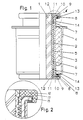
- Auf der Zeichnung ist ein Ausführungsbeispiel der Erfindung dargestellt. Es zeigen:
- Figur 1
- ein Lager der neuen Bauart teilweise im Schnitt und teilweise in Ansicht und
- Figur 2
- eine maßstäbliche Vergrößerung des Ausschnittes "A" in Figur 1.
- Das elastische Gleitlager besteht aus einer starren Innenbuchse 1, einer im wesentlichen ebenfalls starren Außenbuchse 2, einem diese umgebenden Elastomerkörper 3 und einer äußeren Aufnahmebuchse 4, mit dem das Lager beispielsweise in ein Lagerauge eines auf der Zeichnung nicht dargestellten Radlenkers einsetzbar ist, um diesen mittels eines die Innenbuchse 1 durchgreifenden Bolzens an den ebenfalls nicht dargestellten Längsholmen eines Kraftfahrzeuges zu befestigen.
- Zwischen der Innenbuchse 1 und der Außenbuchse 2 befindet sich eine auf der Innenbuchse 1 festhaftend angeordnete Kunststoffschicht 5, an deren äußerer Kontaktfläche Schmiermitteltaschen 6 zur Aufnahme von Fett oder dergleichen für eine Dauerschmierung angeordnet sind. In Nähe der axialen Enden dieser Kunststoffschicht 5 sind Dichtlippen 7 vorgesehen, um das Eindringen von Schmutz zwischen die aufeinandergleitenden Innenflächen der Außenbuchse 2 und der Außenfläche der Kunststoffschicht 5 zu verhindern. An den axialen Enden der Außenbuchse 2 sind durch Verformung des Werkstoffes der Außenbuchse 2 sich radial erstreckende Flanschvorsprünge 8 angeordnet, die mit sich ebenfalls radial erstreckenden Flanschvorsprüngen 9 am Ende der Innenbuchse 1 zusammenwirken. Die letzteren radialen Flanschvorsprünge 9 werden durch eine Kunststoffscheibe 10 gebildet, die mit einer Schnappverbindung auf die axial äußeren Enden der Kunststoffschicht 5 axial unverschiebbar aufgesetzt sind. Dies wird durch einen Kantenwulst 11 an den axialen Enden der Kunststoffschicht 5 und einen Innenwulst 12 der ringförmig ausgebildeten Scheibe 10 mit einem gegenüber dem Kantenwulst 11 geringeren Durchmesser erreicht, so daß die Scheibe 10 unter elastischer radialer Aufweitung über den Kantenwulst 11 hinweggeschoben werden kann und diesen dann mit elastischer Vorspannung hintergreift. Eine solche Ausbildung aus einem Kantenwulst 11 und einem Innenwulst 12 kann eventuell axial mehrfach hintereinander vorgesehen sein, um das Eindringen von Schmutz sicher zu vermeiden. Eine entsprechende Bemessung sorgt dafür, daß die dem radialen Flanschvorsprung 8 an der Außenbuchse 2 zugewendete Fläche der den radialen Flanschvorsprung 9 an der Innenbuchse 1 bildenden Scheibe 10 mit geringer axialer Spannung gegen den Flanschvorsprung 8 gedrückt wird. Zur Abdichtung des zwischen beiden liegenden Spalts ist an der Scheibe 10 ein Kragenrand 13 ausgebildet, der sich nach innen zur Lagermitte erstreckt und den radialen Flanschvorsprung 8 an der Außenbuchse 2 überdeckt.
- Aus der Zeichnung ist deutlich erkennbar, daß die äußere Aufnahmebuchse 4 kürzer als die axiale Länge der Innenbuchse 1 bemessen ist. Dadurch entsteht zwischen der äußeren Aufnahmebuchse 4 und der Radialflanschausbildung an den axialen Enden der Außenbuchse 2 und der Innenbuchse 1 ein Freiraum. Im Bereich dieses Freiraumes kann der Elastomerkörper 3 insgesamt oder nur in begrenzten Bereichen 14 freigeschnitten sein, um eine größere axiale Elastizität des Lagers zu erreichen.
- Dichtungslippen oder andere Dichtungsmittel 15 vergleichbarer Art innerhalb des Kragenrandes 13 verhindern das Eindringen von Schmutz in das Lager, gegebenenfalls in Verbindung mit oder anstelle einer an dem Kragenrand 13 angeordneten oder an diesem ausgebildeten Lippendichtung, die den Flanschvorsprung 8 der Außenbuchse umgreift und an dessen innerer Flanke anliegt.
-
- 1
- Innenbuchse
- 2
- Außenbuchse
- 3
- Elastomerkörper
- 4
- Aufnahmebuchse
- 5
- Kunststoffschicht
- 6
- Schmiermitteltasche
- 7
- Dichtlippe
- 8
- Flanschvorsprung
- 9
- Flanschvorsprung
- 10
- Kunststoffscheibe
- 11
- Randwulst
- 12
- Innenwulst
- 13
- Kragenrand
- 14
- Freischnittbereich
- 15
- Dichtungsmittel
Claims (2)
- Elastisches Gleitlager für Fahrwerksteile in Kraftfahrzeugen, bestehend aus einer starren, am Außenmantel mit einer Schmiermitteltaschen (6) aufweisenden Kunststoffgleitschicht versehenen Innenbuchse (1) und einer auf der Gleitschicht drehbar gelagerten, außen von einem Elastomerkörper (3) umgebenen Außenbuchse (2), wobei zumindest an einem axial äußeren Lagerende zur Bildung einer zwischen der Innenbuchse (1) und der Außenbuchse (2) wirkenden Axiallagerung sowohl die Innenbuchse (1) als auch die Außenbuchse (2) je einen radial nach außen gerichteten Flanschvorsprung aufweisen und einer die Axiallagerung außen an den Flanschvorsprüngen (8,9) umgreifende Dichtung vorgesehen ist, dadurch gekennzeichnet, daß an beiden Lagerenden Axiallagerungen ausgebildet sind, bei denen die Flanschvorsprünge (9) der Innenbuchse (1) Ringscheiben (10) aus Kunststoff sind, die unter elastischer Aufweitung ihres inneren Umfangs mittels einer Schnappverbindung (11,12) axial unverschieblich auf die bis zum axialen Ende der Innenbuchse (1) durchgehend verlaufende Kunststoffgleitschicht (5) aufgesetzt sind, und daß jede Ringscheibe (10) zur Dichtung der Axiallagerung einen zur axialen Lagermitte hin gerichteten, den benachbarten Flanschvorsprung (8) der Außenbuchse (2) übergreifenden Kragen (13) aufweist.
- Gleitlager nach Anspruch 1, dadurch gekennzeichnet, daß die Kunststoffgleitschicht (5) einen äußeren Randwulst (11) und die Ringscheibe (10) einen Innenwulst (12) mit einem gegenüber dem Randwulst (11) verringerten Durchmesser aufweist.
Applications Claiming Priority (2)
| Application Number | Priority Date | Filing Date | Title |
|---|---|---|---|
| DE4036051A DE4036051C1 (de) | 1990-11-13 | 1990-11-13 | |
| DE4036051 | 1990-11-13 |
Publications (3)
| Publication Number | Publication Date |
|---|---|
| EP0485697A2 EP0485697A2 (de) | 1992-05-20 |
| EP0485697A3 EP0485697A3 (en) | 1993-10-06 |
| EP0485697B1 true EP0485697B1 (de) | 1995-11-29 |
Family
ID=6418149
Family Applications (1)
| Application Number | Title | Priority Date | Filing Date |
|---|---|---|---|
| EP91114067A Expired - Lifetime EP0485697B1 (de) | 1990-11-13 | 1991-08-22 | Elastisches Gleitlager |
Country Status (7)
| Country | Link |
|---|---|
| US (1) | US5263778A (de) |
| EP (1) | EP0485697B1 (de) |
| JP (1) | JPH0711288B2 (de) |
| KR (1) | KR100221451B1 (de) |
| BR (1) | BR9101386A (de) |
| DE (1) | DE4036051C1 (de) |
| ES (1) | ES2080868T3 (de) |
Cited By (1)
| Publication number | Priority date | Publication date | Assignee | Title |
|---|---|---|---|---|
| US20140091507A1 (en) * | 2012-09-28 | 2014-04-03 | Redranger Pty Ltd | Bushings for vehicle suspension |
Families Citing this family (30)
| Publication number | Priority date | Publication date | Assignee | Title |
|---|---|---|---|---|
| US5377962A (en) * | 1992-08-08 | 1995-01-03 | Firma Carl Freudenberg | Rotational vibration damper |
| DE4312958A1 (de) * | 1993-04-21 | 1994-10-27 | Lemfoerder Metallwaren Ag | Kunststofflager für Stabilisatoren in Kraftfahrzeugen |
| DE4327474C2 (de) * | 1993-08-16 | 1997-07-31 | Lemfoerder Metallwaren Ag | Gleitlager für Fahrwerksteile in Kraftfahrzeugen |
| US5439295A (en) * | 1994-04-29 | 1995-08-08 | Mikolaizik; Daniel J. | Idler wheel with tapered shaft |
| US5540420A (en) * | 1994-06-07 | 1996-07-30 | Clevite Elastomers | Method of making a bearing structure and bearing so made |
| DE4429102A1 (de) * | 1994-08-17 | 1996-02-22 | Lemfoerder Metallwaren Ag | Radial und axial belastbares Buchsenlager für Fahrwerksteile in Kraftfahrzeugen |
| DE4430037C2 (de) * | 1994-08-24 | 1996-12-12 | Metzeler Gimetall Ag | Lagerbuchse |
| US6170812B1 (en) | 1997-11-13 | 2001-01-09 | Btr Antivibration Systems, Inc. | Slipper bushing incorporating sealing and torque-reducing characteristics |
| US6688767B2 (en) * | 2001-12-11 | 2004-02-10 | The Boeing Company | Self-aligning dynamic hinge sleeve |
| DE10234046A1 (de) * | 2002-07-26 | 2004-02-05 | Audi Ag | Elastisches Lager |
| DE102004031302B4 (de) | 2004-06-28 | 2006-04-13 | Zf Friedrichshafen Ag | Ringscheibe für ein Gleitlager |
| DE102004031559B4 (de) * | 2004-06-29 | 2019-02-07 | Boge Elastmetall Gmbh | Elastomeres Buchsenlager mit verbessertem Torsionsverhalten |
| DE102004035073A1 (de) * | 2004-07-20 | 2006-03-16 | Zf Friedrichshafen Ag | Lageranordnung |
| FR2881808B1 (fr) * | 2005-02-07 | 2007-05-11 | Peugeot Citroen Automobiles Sa | Palier de fixation d'une barre anti-devers au chassis d'un vehicule automobile |
| DE102006021011B4 (de) * | 2006-05-04 | 2021-05-12 | Boge Elastmetall Gmbh | Buchsenlager mit axialseitig profiliertem Lagerkörper |
| RU2377449C2 (ru) * | 2007-02-26 | 2009-12-27 | Открытое Акционерное Общество "Государственный Ракетный Центр Имени Академика В.П. Макеева" | Подшипник скольжения |
| DE102010036027A1 (de) * | 2010-08-31 | 2012-03-01 | Bpw Bergische Achsen Kg | Stahlgummibuchse |
| KR101550598B1 (ko) * | 2011-07-29 | 2015-09-18 | 현대자동차 주식회사 | 자동차용 스태빌라이저 바의 마운트 부시 |
| KR101542956B1 (ko) * | 2011-07-29 | 2015-08-07 | 현대자동차 주식회사 | 자동차용 스태빌라이저 바의 마운트 부시 |
| US9022403B2 (en) * | 2013-03-11 | 2015-05-05 | Nissan North America, Inc. | Vehicle front suspension |
| US8870205B2 (en) | 2013-03-11 | 2014-10-28 | Nissan North America, Inc. | Vehicle front suspension |
| CN104421339B (zh) * | 2013-08-19 | 2017-08-22 | 广州汽车集团股份有限公司 | 一种自润滑橡胶衬套及汽车悬架系统导向装置 |
| KR102118863B1 (ko) | 2015-06-30 | 2020-06-05 | 생-고뱅 퍼포먼스 플라스틱스 코포레이션 | 미끄럼 베어링 |
| US10414427B2 (en) * | 2016-08-16 | 2019-09-17 | Brc Rubber & Plastics Inc. | Steering column and bearing assembly |
| DE102016125856A1 (de) * | 2016-12-29 | 2018-07-05 | Benteler Automobiltechnik Gmbh | Lageranordnung für ein Fahrzeug |
| KR101860828B1 (ko) * | 2017-04-20 | 2018-05-24 | 주식회사 대흥알앤티 | 자동차 서브 프레임용 부시 |
| EP3673185B1 (de) * | 2017-08-21 | 2023-11-08 | BAE Systems PLC | Antivibrationsmontage |
| CN111998060A (zh) * | 2020-07-03 | 2020-11-27 | 黄丽婷 | 一种耐磨防腐橡胶衬套组件 |
| EP4298353A1 (de) * | 2021-02-26 | 2024-01-03 | De'Longhi Braun Household GmbH | Lageranordnung |
| CN117015667A (zh) * | 2021-02-26 | 2023-11-07 | 德龙博朗家电有限公司 | 轴承组件 |
Family Cites Families (14)
| Publication number | Priority date | Publication date | Assignee | Title |
|---|---|---|---|---|
| US3298762A (en) * | 1962-12-18 | 1967-01-17 | Gen Tire & Rubber Co | Self-lubricating joint |
| GB1193636A (en) * | 1966-10-14 | 1970-06-03 | Carr Fastener Co Ltd | An Insert for Assembly in an Aperture in a Support. |
| GB1205749A (en) * | 1966-11-29 | 1970-09-16 | Silentbloc | Pivotal joint |
| GB1240885A (en) * | 1967-11-24 | 1971-07-28 | Schmidt Gmbh Karl | Journal bearing |
| FR2202556A5 (de) * | 1972-10-06 | 1974-05-03 | Kleber Colombes | |
| US4123122A (en) * | 1976-07-06 | 1978-10-31 | The Torrington Company | Bearing element |
| FR2442371A1 (fr) * | 1978-11-22 | 1980-06-20 | Chromex Sa | Palier elastique autolubrifiant |
| US4717268A (en) * | 1981-04-20 | 1988-01-05 | Kamatics Corporation | Bearing construction |
| DE3613123A1 (de) * | 1986-04-18 | 1987-10-29 | Lemfoerder Metallwaren Ag | Elastisches dreh- gleitlager fuer fahrwerksteile in kraftfahrzeugen |
| DE3624280A1 (de) * | 1986-07-18 | 1988-01-28 | Trw Ehrenreich Gmbh | Gelenk fuer uebertragungsgestaenge in kraftfahrzeugen |
| DE3707600A1 (de) * | 1987-03-10 | 1988-09-22 | Vdo Schindling | Lagerung der motorwelle eines pumpenantriebs |
| DE3800314A1 (de) * | 1988-01-08 | 1989-07-27 | Lemfoerder Metallwaren Ag | Gleitlager mit dauerschmierung zur lagerung von fahrwerksteilen in kraftfahrzeugen |
| DE3804886A1 (de) * | 1988-02-17 | 1989-08-31 | Freudenberg Carl Fa | Buchsenlager |
| DE8811326U1 (de) * | 1988-09-07 | 1988-12-15 | Kress-elektrik GmbH & Co, Elektromotorenfabrik, 7457 Bisingen | Wellenlagerung für einen Elektromotor |
-
1990
- 1990-11-13 DE DE4036051A patent/DE4036051C1/de not_active Expired - Fee Related
-
1991
- 1991-04-05 BR BR919101386A patent/BR9101386A/pt not_active IP Right Cessation
- 1991-05-28 KR KR1019910008721A patent/KR100221451B1/ko not_active Expired - Fee Related
- 1991-08-22 ES ES91114067T patent/ES2080868T3/es not_active Expired - Lifetime
- 1991-08-22 EP EP91114067A patent/EP0485697B1/de not_active Expired - Lifetime
- 1991-10-08 JP JP3260087A patent/JPH0711288B2/ja not_active Expired - Fee Related
- 1991-10-10 US US07/777,753 patent/US5263778A/en not_active Expired - Lifetime
Cited By (1)
| Publication number | Priority date | Publication date | Assignee | Title |
|---|---|---|---|---|
| US20140091507A1 (en) * | 2012-09-28 | 2014-04-03 | Redranger Pty Ltd | Bushings for vehicle suspension |
Also Published As
| Publication number | Publication date |
|---|---|
| US5263778A (en) | 1993-11-23 |
| KR100221451B1 (ko) | 1999-09-15 |
| EP0485697A3 (en) | 1993-10-06 |
| JPH04266611A (ja) | 1992-09-22 |
| JPH0711288B2 (ja) | 1995-02-08 |
| DE4036051C1 (de) | 1992-04-09 |
| ES2080868T3 (es) | 1996-02-16 |
| BR9101386A (pt) | 1992-06-23 |
| EP0485697A2 (de) | 1992-05-20 |
| KR920010171A (ko) | 1992-06-26 |
Similar Documents
| Publication | Publication Date | Title |
|---|---|---|
| EP0485697B1 (de) | Elastisches Gleitlager | |
| DE69427446T2 (de) | Kunstharz Lager mit einem scheibenförmigen axialen Lagerelement und einem radialen Lagerelement in der Form einer geschlitzte Hülse | |
| EP0487891B1 (de) | Elastisches Gleitlager | |
| EP0485696B1 (de) | Elastisches Gleitlager | |
| DE3885070T2 (de) | Gleitringdichtung und Lagervorrichtung. | |
| DE2835971A1 (de) | Rad- und lageranordnung | |
| WO2008014768A2 (de) | Abgedichtetes wälzlager | |
| DE3806397C2 (de) | ||
| EP0274584A1 (de) | Vorrichtung zum Abdichten der Lagerbüchse eines Kreuzgelenkes | |
| DE102004031302B4 (de) | Ringscheibe für ein Gleitlager | |
| DE4312958A1 (de) | Kunststofflager für Stabilisatoren in Kraftfahrzeugen | |
| EP0671570B1 (de) | Drehelastische Kupplung | |
| DE4120772C2 (de) | Radial und axial belastbares Drehgleitlager für Fahrwerksteile in Kraftfahrzeugen | |
| DE4204252C2 (de) | Kunststofflager für Stabilisatoren in Kraftfahrzeugen | |
| DE2362764A1 (de) | Dichtung zum abdichten der antriebswellen am gehaeuse des ausgleichsgetriebes eines kraftfahrzeuges | |
| EP0811778B1 (de) | Zapfenkreuzgarnitur für Kreuzgelenke | |
| DE102018216781A1 (de) | Dichtelement, Spindelantrieb und Aktuator einer Lenkung mit Spindelantrieb | |
| DE1750844A1 (de) | Lageranordnung bei Waelzlagern | |
| EP1612448B1 (de) | Elastomeres Buchsenlager mit verbessertem Torsionsverhalten | |
| DE3346666A1 (de) | Elastisches dreh-gleitlager | |
| DE102018117595A1 (de) | Federbeinlager | |
| DE1111957B (de) | Aus elastischem Werkstoff bestehende Lagerung zur Aufnahme von in radialer Richtung auftretenden Kraeften, vorzugsweise Lagerung fuer Torsionsfederstaebe an Kraftfahrzeugen | |
| DE3800314C2 (de) | ||
| DE102015220151A1 (de) | Lageranordnung und Dichtung | |
| DE602004006557T2 (de) | Kreuzgelenk mit einer Vorrichtung zum Abdichten der Lagerbüchse des Kreuzgelenkes |
Legal Events
| Date | Code | Title | Description |
|---|---|---|---|
| PUAI | Public reference made under article 153(3) epc to a published international application that has entered the european phase |
Free format text: ORIGINAL CODE: 0009012 |
|
| AK | Designated contracting states |
Kind code of ref document: A2 Designated state(s): ES FR GB IT SE |
|
| PUAL | Search report despatched |
Free format text: ORIGINAL CODE: 0009013 |
|
| AK | Designated contracting states |
Kind code of ref document: A3 Designated state(s): ES FR GB IT SE |
|
| 17P | Request for examination filed |
Effective date: 19931105 |
|
| 17Q | First examination report despatched |
Effective date: 19940422 |
|
| GRAA | (expected) grant |
Free format text: ORIGINAL CODE: 0009210 |
|
| AK | Designated contracting states |
Kind code of ref document: B1 Designated state(s): ES FR GB IT SE |
|
| GBT | Gb: translation of ep patent filed (gb section 77(6)(a)/1977) |
Effective date: 19960110 |
|
| REG | Reference to a national code |
Ref country code: ES Ref legal event code: FG2A Ref document number: 2080868 Country of ref document: ES Kind code of ref document: T3 |
|
| ITF | It: translation for a ep patent filed | ||
| ET | Fr: translation filed | ||
| PLBE | No opposition filed within time limit |
Free format text: ORIGINAL CODE: 0009261 |
|
| STAA | Information on the status of an ep patent application or granted ep patent |
Free format text: STATUS: NO OPPOSITION FILED WITHIN TIME LIMIT |
|
| 26N | No opposition filed | ||
| REG | Reference to a national code |
Ref country code: GB Ref legal event code: IF02 |
|
| PGFP | Annual fee paid to national office [announced via postgrant information from national office to epo] |
Ref country code: ES Payment date: 20070926 Year of fee payment: 17 |
|
| PGFP | Annual fee paid to national office [announced via postgrant information from national office to epo] |
Ref country code: GB Payment date: 20070822 Year of fee payment: 17 |
|
| PGFP | Annual fee paid to national office [announced via postgrant information from national office to epo] |
Ref country code: SE Payment date: 20070807 Year of fee payment: 17 Ref country code: IT Payment date: 20070828 Year of fee payment: 17 |
|
| PGFP | Annual fee paid to national office [announced via postgrant information from national office to epo] |
Ref country code: FR Payment date: 20070808 Year of fee payment: 17 |
|
| EUG | Se: european patent has lapsed | ||
| GBPC | Gb: european patent ceased through non-payment of renewal fee |
Effective date: 20080822 |
|
| REG | Reference to a national code |
Ref country code: FR Ref legal event code: ST Effective date: 20090430 |
|
| PG25 | Lapsed in a contracting state [announced via postgrant information from national office to epo] |
Ref country code: IT Free format text: LAPSE BECAUSE OF NON-PAYMENT OF DUE FEES Effective date: 20080822 Ref country code: FR Free format text: LAPSE BECAUSE OF NON-PAYMENT OF DUE FEES Effective date: 20080901 |
|
| REG | Reference to a national code |
Ref country code: ES Ref legal event code: FD2A Effective date: 20080823 |
|
| PG25 | Lapsed in a contracting state [announced via postgrant information from national office to epo] |
Ref country code: GB Free format text: LAPSE BECAUSE OF NON-PAYMENT OF DUE FEES Effective date: 20080822 |
|
| PG25 | Lapsed in a contracting state [announced via postgrant information from national office to epo] |
Ref country code: ES Free format text: LAPSE BECAUSE OF NON-PAYMENT OF DUE FEES Effective date: 20080823 |
|
| PG25 | Lapsed in a contracting state [announced via postgrant information from national office to epo] |
Ref country code: SE Free format text: LAPSE BECAUSE OF NON-PAYMENT OF DUE FEES Effective date: 20080823 |