EP0484694A2 - Système de commande d'une suspension - Google Patents
Système de commande d'une suspension Download PDFInfo
- Publication number
- EP0484694A2 EP0484694A2 EP91117426A EP91117426A EP0484694A2 EP 0484694 A2 EP0484694 A2 EP 0484694A2 EP 91117426 A EP91117426 A EP 91117426A EP 91117426 A EP91117426 A EP 91117426A EP 0484694 A2 EP0484694 A2 EP 0484694A2
- Authority
- EP
- European Patent Office
- Prior art keywords
- chamber
- line
- control valve
- control
- spring
- Prior art date
- Legal status (The legal status is an assumption and is not a legal conclusion. Google has not performed a legal analysis and makes no representation as to the accuracy of the status listed.)
- Withdrawn
Links
Images
Classifications
-
- B—PERFORMING OPERATIONS; TRANSPORTING
- B60—VEHICLES IN GENERAL
- B60G—VEHICLE SUSPENSION ARRANGEMENTS
- B60G17/00—Resilient suspensions having means for adjusting the spring or vibration-damper characteristics, for regulating the distance between a supporting surface and a sprung part of vehicle or for locking suspension during use to meet varying vehicular or surface conditions, e.g. due to speed or load
- B60G17/06—Characteristics of dampers, e.g. mechanical dampers
- B60G17/08—Characteristics of fluid dampers
-
- B—PERFORMING OPERATIONS; TRANSPORTING
- B60—VEHICLES IN GENERAL
- B60G—VEHICLE SUSPENSION ARRANGEMENTS
- B60G17/00—Resilient suspensions having means for adjusting the spring or vibration-damper characteristics, for regulating the distance between a supporting surface and a sprung part of vehicle or for locking suspension during use to meet varying vehicular or surface conditions, e.g. due to speed or load
- B60G17/02—Spring characteristics, e.g. mechanical springs and mechanical adjusting means
- B60G17/04—Spring characteristics, e.g. mechanical springs and mechanical adjusting means fluid spring characteristics
- B60G17/056—Regulating distributors or valves for hydropneumatic systems
-
- B—PERFORMING OPERATIONS; TRANSPORTING
- B60—VEHICLES IN GENERAL
- B60G—VEHICLE SUSPENSION ARRANGEMENTS
- B60G2202/00—Indexing codes relating to the type of spring, damper or actuator
- B60G2202/10—Type of spring
- B60G2202/15—Fluid spring
- B60G2202/154—Fluid spring with an accumulator
-
- B—PERFORMING OPERATIONS; TRANSPORTING
- B60—VEHICLES IN GENERAL
- B60G—VEHICLE SUSPENSION ARRANGEMENTS
- B60G2400/00—Indexing codes relating to detected, measured or calculated conditions or factors
- B60G2400/90—Other conditions or factors
- B60G2400/91—Frequency
-
- B—PERFORMING OPERATIONS; TRANSPORTING
- B60—VEHICLES IN GENERAL
- B60G—VEHICLE SUSPENSION ARRANGEMENTS
- B60G2500/00—Indexing codes relating to the regulated action or device
- B60G2500/10—Damping action or damper
-
- B—PERFORMING OPERATIONS; TRANSPORTING
- B60—VEHICLES IN GENERAL
- B60G—VEHICLE SUSPENSION ARRANGEMENTS
- B60G2500/00—Indexing codes relating to the regulated action or device
- B60G2500/20—Spring action or springs
-
- B—PERFORMING OPERATIONS; TRANSPORTING
- B60—VEHICLES IN GENERAL
- B60G—VEHICLE SUSPENSION ARRANGEMENTS
- B60G2500/00—Indexing codes relating to the regulated action or device
- B60G2500/30—Height or ground clearance
-
- B—PERFORMING OPERATIONS; TRANSPORTING
- B60—VEHICLES IN GENERAL
- B60G—VEHICLE SUSPENSION ARRANGEMENTS
- B60G2600/00—Indexing codes relating to particular elements, systems or processes used on suspension systems or suspension control systems
- B60G2600/18—Automatic control means
Definitions
- the invention relates to a system for regulating a chassis, in particular for regulating spring cylinders, which can simultaneously perform the function of a semi-active shock absorber and are arranged between wheel suspensions and vehicle body according to the preamble of claim 1.
- the directional damper setting for example by means of valves which can be set as a function of control signals, takes place as a function of sensor signals which record various parameters of the driving state (for example vehicle speed, vehicle inclination, lateral, vertical acceleration, lifting, pitching and rolling movements).
- active interventions for the reaction of pitching, lifting and rolling movements are to be implemented in the low-frequency range of the body movements.
- passive control signals are distinguished from active control signals. Passive control signals are aimed at a slow, adaptive adjustment of the damping depending on, for example, the driver's desired driving behavior, the road conditions or the vehicle speed.
- the active control signals should have a direct influence on the respective absolute speed of the vehicle body (lifting, lowering, pitching, rolling) within the shortest possible time intervals.
- the entire damper system can be designed so that the passive damping control increases or decreases the damping effect with respect to tension and compression in the same direction, while the active damping control also makes the damping as a function of external signals asymmetrical, i.e. the damping effect in the compression and rebound stages is opposite influenced. Overall, this results in a so-called semi-active damper system.
- a system for regulating shock absorbers is known for example from DE-PS 16 30 058.
- There two working chambers of a shock absorber or shock absorber are connected via external lines to a device consisting of a pump and two accumulators.
- a device consisting of a pump and two accumulators.
- only single-acting check valves are provided as valves.
- the damper hardness of a shock absorber cannot be changed, because for this purpose energy must be supplied from the outside via the pump, which takes place relatively slowly and means a certain power requirement.
- DE-OS 33 04 815 also shows a possibility for regulating shock absorbers, the spring hardness and the damper hardness being optimized for a medium operating case and the corresponding parts or their parameters being structurally determined thereon. These parameters then remain unchanged while driving. In this way, however, extreme operating cases, such as, for example, an empty or a fully loaded vehicle or changing movement parameters of the vehicle (cornering, braking, acceleration, comfortable driving on the freeway or the like) are not recorded.
- both working chambers of a shock absorber are each connected to one another crosswise and in parallel to one another via oppositely directed valves which allow a flow of the pressure medium only in one direction, in which case the quantity of pressure medium let through by these valves is still “active” by means of appropriate control of the valves by means of suitable processed sensor signals is determined.
- the spring lying outside remains completely passive, so that the overall system is a semi-active control.
- the semi-active damper control described above is not sufficient to optimally calm the body. This requires a partially active chassis control system that feeds or dissipates active energy to the spring cylinder.
- the object of the present invention is to be able to set a low-frequency pressure curve associated with the movement of the vehicle body in accordance with a target specification, without high-frequency pressure overlaps, which result from road conditions on the part of the shock absorber, having an effect on the actuator.
- the invention according to the characterizing part of claim 1 has the advantage that the corresponding control valve is not controlled and switched from the outside in essential working positions, but responds to pressure in the line to the shock absorber chamber, so that this essential parameter is not detected by pressure sensors and then must be implemented in complicated control and regulation units. As soon as the pressure in the line to the chamber changes, the control valve can also be activated and switched to another working position.
- a branch from this branch line to the chamber of the spring cylinder is therefore preferably provided, which leads into a chamber of the control valve and can pressurize a piston of a slide valve there.
- this slide has three working positions, namely a return position, a blocking position and an inlet position. Depending on how high the pressure in the chamber is, the slide is brought into a corresponding working position.
- the slide is supported by a piston in the chamber against a spring, while on the other hand it is attacked by an actuating magnet.
- Circuits in certain working positions are also possible via this actuating magnet, whereby this applies above all to a circuit in the inlet position in which the slide must be guided against the pressure of the spring in the chamber.
- a throttle should preferably also be switched on in the discharge line, so that not every, even slight, pressure change leads to a switching of the control valve.
- a derivation is assigned to a reservoir, so that pressure medium can only be accommodated in this reservoir before the control valve responds. This also ensures that, in particular, high-frequency pressure overlaps can be absorbed by uneven roads without the control valve having to respond.
- a quick-switching damper valve should be assigned to the control valve in the control element mentioned above.
- This fast-switching damper valve also serves to generate appropriately adapted damper forces for wheel and body damping in the event of significant road unevenness.
- the control valve should be able to set a low-frequency pressure curve associated with the movement of the vehicle body in accordance with a target specification.
- Corresponding pumps and accumulators as well as control and monitoring devices are of course used for this purpose, but are not dealt with in more detail.
- control valve which is very robust and hardly temperature-dependent.
- valve piston When a pressure change in the shock absorber is specified, the valve piston is deflected from its rest position by the magnet and moved into a corresponding working position. Due to the pressure change in the line, there is a restoring force on the valve piston, which counteracts the magnetic force and moves the valve piston into its rest position. There is no external position control on the valve itself. A lower computing power of the system computer is required, since no pressure control loop and no signal processing is necessary.
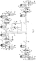
- shock absorbers 1 for example of a motor vehicle, are each connected via a branch line 2 to a main line 3, into which a line 4 leads to a storage container 5. From this reservoir 5, hydraulic fluid can be removed by means of a pump 6 with the interposition of a hydraulic fluid and fed into the main line 3. Primarily, the pump 6 serves to fill up stores 7, which are switched on as the first control elements in the respective branch line 2.
- the pump 6 switches off. If the pressure in line 4 or main line 3 is too high due to the pump 6 being pumped, excess hydraulic pressure medium can flow back to the reservoir 5 via a pressure limiting valve 8. In this way, even if, for example, an undesired continuous operation of the pump 6 is effected, the accumulators 7 are filled with pressure medium only to a previously set and desired extent.
- Each store 7 is followed in each branch line 2 by a control element 9, which essentially consists of a control valve 10, a damper valve 11 and a throttle 12.
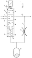
- the control valve 10 is described in more detail in relation to FIG. 2.
- the damper valve 11 is a fast-switching valve and has a passage position and a one-sided blocking position occupied by a check valve, so that a backflow of pressure medium from the shock absorber 1 can be prevented.
- the throttle 12 is located in a discharge line 13, via which a chamber 26 (see FIG. 2) in the control valve 10 is connected to the branch line 2 between the damper valve 11 and the control valve 10.
- the control element 9 is followed by a further accumulator 14 connected to a line 2a.
- This accumulator 14 is used in particular to receive and compensate for pressure medium when the damper valve 11 is closed.
- the line 2a opens into an upper chamber 15 of the shock absorber 1.
- a damper piston 16 separates the upper chamber 15 from a lower chamber 17, which is also traversed by a piston rod 18.
- Upper chamber 15 and lower chamber 17 together form a cylinder 19 which is fastened, for example, to a chassis of a motor vehicle, not shown.
- the piston 18, on the other hand, is connected, for example, to a wheel axle (not shown in more detail).
- a return line 20 is also connected to the control valve 10, a common connecting line 21 opening into the storage container 5.
- a slide 22 is seated in the control valve 10, which is supported at one end via a spring 23 against an actuating magnet 24.
- the slide 22 engages with a piston 25 in the chamber 26 and is supported in this chamber 26 by a spring 27 against the bottom 28 of the control valve 10.
- This piston 25 can be acted upon in the chamber 26 by pressure from the discharge line 13.
- the branch line 2 is interrupted from the connection to line 2a and the return line 20 is blocked. If the slide 22 is shifted to the right, the line 2a between the shock absorber 1 and the control valve 10 is connected to the return.
- the slide 22 is shifted to the left, the return 20 remains blocked while a passage of pressure medium from the accumulator 7 or the pump 6 to the shock absorber 1 is opened.
- the middle blocking position of the slide 22 is identified by 29, the return position by 30 and the inlet position by 31.
- the chassis control according to the invention takes place as follows: If only passive chassis control is required, the damper valve 11 is switched to the blocking position, so that the shock absorber can carry out its normal, known activity, the damping being carried out essentially by damping valves 32 present in the damper piston 16.
- the memory 14 also acts as an expansion tank.
- the damper valve 11 switches to the through position and the regulating valve 10 starts operating. If an inflow of pressure medium to the shock absorber 1 is required, the control valve 10 is switched to the inflow position 31 via the actuating magnet 24. If the mean pressure in the chambers 15 and 17 subsequently increases, pressure medium flows through the throttle 12 into the chamber 26 and moves the slide 22 into the closed position 29 via the piston 25. For this reason, additional pressure sensors can be located on the shock absorber 1 or in the line 2a omitted. For this reason, high-frequency wheel movements and low-frequency movements of a vehicle body are processed separately by the control element 9. The control valve 10 can adjust the low-frequency pressure curve associated with the movement of the vehicle body in accordance with a target specification.
- High-frequency pressure overlaps which result, for example, from road bumps on the part of the shock absorber, are excluded from direct intervention on the control element 30 via the hydraulic low-pass filter consisting of throttle point 12 and accumulator 33.
- low-frequency pressure changes according to the target allocation can directly access the control element and specify an average pressure in the spring cylinder.
- the adjustable setpoint pressure thus results from an equilibrium of forces between the magnetic force of the actuating magnet 24 and the force from the pressure in the chamber 26 and the effective area on the slide 22.
- an additional memory 33 is also associated with the derivative 13 between the throttle 12 and the control valve 10.
- the accumulator must be designed so that changes in position of the piston 25 have no noticeable influence on the accumulator pressure, for example when the slide 22 is displaced into its inlet position 31 by the actuating magnet 24.
Landscapes
- Engineering & Computer Science (AREA)
- Mechanical Engineering (AREA)
- Vehicle Body Suspensions (AREA)
Applications Claiming Priority (2)
| Application Number | Priority Date | Filing Date | Title |
|---|---|---|---|
| DE4035313A DE4035313C2 (de) | 1990-11-07 | 1990-11-07 | System zum Regeln eines Fahrwerkes |
| DE4035313 | 1990-11-07 |
Publications (2)
| Publication Number | Publication Date |
|---|---|
| EP0484694A2 true EP0484694A2 (fr) | 1992-05-13 |
| EP0484694A3 EP0484694A3 (en) | 1993-11-18 |
Family
ID=6417770
Family Applications (1)
| Application Number | Title | Priority Date | Filing Date |
|---|---|---|---|
| EP19910117426 Withdrawn EP0484694A3 (en) | 1990-11-07 | 1991-10-12 | Suspension control system |
Country Status (4)
| Country | Link |
|---|---|
| US (1) | US5205581A (fr) |
| EP (1) | EP0484694A3 (fr) |
| JP (1) | JP3160032B2 (fr) |
| DE (1) | DE4035313C2 (fr) |
Families Citing this family (8)
| Publication number | Priority date | Publication date | Assignee | Title |
|---|---|---|---|---|
| US5588510A (en) * | 1995-09-25 | 1996-12-31 | Husco International, Inc. | Variable damping force shock absorber |
| DE10158913B4 (de) * | 2001-11-30 | 2004-07-22 | Audi Ag | Verfahren und Vorrichtung zur Voraktivierung mindestens einer Fahrzeugkomponente |
| US7946163B2 (en) * | 2007-04-02 | 2011-05-24 | Penske Racing Shocks | Methods and apparatus for developing a vehicle suspension |
| DE102009027939A1 (de) * | 2009-02-03 | 2010-08-05 | Robert Bosch Gmbh | Verfahren zur Fahrwerkregelung eines Kraftfahrzeugs, sowie Vorrichtung zur Durchführung |
| DE102016216546A1 (de) * | 2016-09-01 | 2018-03-01 | Zf Friedrichshafen Ag | Schwingungsdämpfer sowie Kraftfahrzeug |
| DE102018118911A1 (de) * | 2018-08-03 | 2020-02-06 | Thyssenkrupp Ag | Schwingungsdämpfer, Fahrzeug, Verwendung eines Absperrventils und Verfahren zum Befüllen |
| US20220203801A1 (en) * | 2019-05-22 | 2022-06-30 | Mario Rolando NAVARRETE | Land vehicle |
| US11358430B2 (en) * | 2020-06-16 | 2022-06-14 | Deere & Company | Suspension system with variable roll resistance |
Family Cites Families (16)
| Publication number | Priority date | Publication date | Assignee | Title |
|---|---|---|---|---|
| DE1277040B (de) * | 1966-03-04 | 1968-09-05 | Daimler Benz Ag | Hydropneumatische Federung mit Niveauregelung fuer Fahrzeuge, insbesondere fuer Nutzkraftfahrzeuge |
| DE1630058B1 (de) * | 1967-10-09 | 1971-10-28 | Hoesch Ag | Hydropneumatisches Federbein mit innerer Niveauregeleinrichtung |
| US3807678A (en) * | 1972-09-19 | 1974-04-30 | Lord Corp | System for controlling the transmission of energy between spaced members |
| US4620619A (en) * | 1982-05-20 | 1986-11-04 | Atsugi Motor Parts Co., Ltd. | Variable-damping-force shock absorber |
| DE3524863A1 (de) * | 1985-04-12 | 1986-10-30 | Robert Bosch Gmbh, 7000 Stuttgart | Verfahren und vorrichtung zum steuern der federhaerte, insbesondere bei fahrzeugen |
| DE3524862A1 (de) * | 1985-04-12 | 1986-10-30 | Robert Bosch Gmbh, 7000 Stuttgart | Vorrichtung zur daempfung von bewegungsablaeufen |
| DE3610937A1 (de) * | 1986-04-02 | 1987-10-08 | Bosch Gmbh Robert | Vorrichtung zur daempfung von bewegungsablaeufen |
| DE3611315A1 (de) * | 1986-04-04 | 1987-10-08 | Bosch Gmbh Robert | Regelbarer stossdaempfer |
| DE3644447A1 (de) * | 1986-12-24 | 1988-07-07 | Bosch Gmbh Robert | Vorrichtung zur daempfung von bewegungsablaeufen |
| DE3823840A1 (de) * | 1987-07-18 | 1989-01-26 | Barmag Barmer Maschf | Stossdaempfer |
| JPH082727B2 (ja) * | 1988-01-26 | 1996-01-17 | 日産自動車株式会社 | アクティブサスペンション用油圧回路 |
| JPH0254007A (ja) * | 1988-08-12 | 1990-02-23 | Nikko Co Ltd | アスファルトプラント |
| EP0394389A1 (fr) * | 1988-09-02 | 1990-10-31 | Electro Hydraulic Technology Ltd. | Dispositif de commande de suspension |
| JP2528964B2 (ja) * | 1989-03-27 | 1996-08-28 | 日産自動車株式会社 | 能動型サスペンション |
| JP2509328B2 (ja) * | 1989-04-28 | 1996-06-19 | 日産自動車株式会社 | 車両用流体圧供給装置 |
| JP2594156B2 (ja) * | 1989-08-30 | 1997-03-26 | トヨタ自動車株式会社 | 流体圧式アクティブサスペンション |
-
1990
- 1990-11-07 DE DE4035313A patent/DE4035313C2/de not_active Expired - Fee Related
-
1991
- 1991-10-12 EP EP19910117426 patent/EP0484694A3/de not_active Withdrawn
- 1991-11-05 JP JP28829391A patent/JP3160032B2/ja not_active Expired - Fee Related
- 1991-11-06 US US07/788,670 patent/US5205581A/en not_active Expired - Fee Related
Also Published As
| Publication number | Publication date |
|---|---|
| JPH04262909A (ja) | 1992-09-18 |
| DE4035313C2 (de) | 2000-03-02 |
| JP3160032B2 (ja) | 2001-04-23 |
| DE4035313A1 (de) | 1992-05-14 |
| US5205581A (en) | 1993-04-27 |
| EP0484694A3 (en) | 1993-11-18 |
Similar Documents
| Publication | Publication Date | Title |
|---|---|---|
| DE69223149T2 (de) | Fahrzeugaufhängungssystem | |
| DE69531448T2 (de) | Hydraulische aufhängung mit unabhängiger regelung von nick- und rollbewegung | |
| DE3910445C2 (fr) | ||
| DE3485842T2 (de) | Computeroptimiertes regelbares aufhaengungssystem. | |
| DE102006002983B4 (de) | Aktives Fahrwerksystem eines Fahrzeugs | |
| DE2923357C2 (de) | Sich regelnde Aufhängungen für die Zelle eines Kraftfahrzeugs | |
| EP0367949B1 (fr) | Système de suspension pour véhicules | |
| DE3919303C2 (fr) | ||
| DE19703872A1 (de) | Hydraulischer Dämpfer | |
| EP0351537B1 (fr) | Système à ressort et amortisseur pour véhicules | |
| DE112013006374T5 (de) | Aktive und passive Aufhängung mit Optimierung des Energieverbrauchs | |
| EP0197317A2 (fr) | Système pour commander la raideur des ressorts, en particulier pour des suspensions de roues pour véhicules | |
| DE4138831A1 (de) | Verfahren und system zum regeln einer aktiven aufhaengung eines fahrzeuges | |
| DE4019732A1 (de) | Vorrichtung zur steuerung aktiver radaufhaengungen von fahrzeugen | |
| AT502330B1 (de) | Verfahren zum betrieb einer einrichtung für eine reifenfüllanlage für kraftfahrzeuge | |
| EP0482323A1 (fr) | Système de support à ressorts, notamment pour véhicules | |
| EP1241031B1 (fr) | Suspension hydropneumatique à réglage d'assiette pour véhicules, notamment pour véhicules totalement suspendus | |
| DE68908846T2 (de) | Hydraulisches Fahrzeugaufhängungssystem. | |
| EP0444278B1 (fr) | Dispositif pour le réglage actif de mouvements de la caisse de véhicules automobiles | |
| DE4035313C2 (de) | System zum Regeln eines Fahrwerkes | |
| DE3308011C2 (de) | Aktives Federungssystem | |
| EP1778508A1 (fr) | Dispositif de suspenson | |
| DE4193088C2 (de) | Hydraulischer Schwingungsdämpfer mit integrierter Nivellier-Regeleinrichtung | |
| DE3936987A1 (de) | Hydropneumatisches federungssystem | |
| DE3823840C2 (fr) |
Legal Events
| Date | Code | Title | Description |
|---|---|---|---|
| PUAI | Public reference made under article 153(3) epc to a published international application that has entered the european phase |
Free format text: ORIGINAL CODE: 0009012 |
|
| AK | Designated contracting states |
Kind code of ref document: A2 Designated state(s): DE FR GB SE |
|
| PUAL | Search report despatched |
Free format text: ORIGINAL CODE: 0009013 |
|
| AK | Designated contracting states |
Kind code of ref document: A3 Designated state(s): DE FR GB SE |
|
| STAA | Information on the status of an ep patent application or granted ep patent |
Free format text: STATUS: THE APPLICATION IS DEEMED TO BE WITHDRAWN |
|
| 18D | Application deemed to be withdrawn |
Effective date: 19940503 |