EP0484683A1 - Sportschuh, insbesondere für Gehen und Skilanglauf, mit abnehmbarer Schaftmanschette - Google Patents
Sportschuh, insbesondere für Gehen und Skilanglauf, mit abnehmbarer Schaftmanschette Download PDFInfo
- Publication number
- EP0484683A1 EP0484683A1 EP91117102A EP91117102A EP0484683A1 EP 0484683 A1 EP0484683 A1 EP 0484683A1 EP 91117102 A EP91117102 A EP 91117102A EP 91117102 A EP91117102 A EP 91117102A EP 0484683 A1 EP0484683 A1 EP 0484683A1
- Authority
- EP
- European Patent Office
- Prior art keywords
- collar
- head
- buttonhole
- plane
- sports shoe
- Prior art date
- Legal status (The legal status is an assumption and is not a legal conclusion. Google has not performed a legal analysis and makes no representation as to the accuracy of the status listed.)
- Granted
Links
Images



Classifications
-
- A—HUMAN NECESSITIES
- A43—FOOTWEAR
- A43B—CHARACTERISTIC FEATURES OF FOOTWEAR; PARTS OF FOOTWEAR
- A43B5/00—Footwear for sporting purposes
- A43B5/04—Ski or like boots
- A43B5/0411—Ski or like boots for cross-country
Definitions
- the present invention relates to a sports shoe, intended for sports requiring longitudinal mobility of the foot relative to the leg and good ankle grip and which is more specifically adapted to walking (hiking, trekking) or to skiing. background.
- this is defined by repetitive cycles in which alternate, motor phases and rest phase; a motor phase corresponding to an impulse provided by one leg, being followed by a rest phase where one slides on the other leg, the skis remaining substantially parallel during these cycles.
- the lower train works on sliding supports, which forces the skier to exert a thrust directed laterally, with respect to its trajectory, by making its skis diverge to rest on the edges .
- the alternative step requires only a front / rear flexibility in the direction of movement for the movements of extension / flexion of the leg, whereas in the case of the skater's step, an additional requirement is required which is added to the previous one and which consists in obtaining a maximum rigidity of the shoe in the direction perpendicular to the movement for good grip of the ankle. It should be noted that the requirements for shoes for skating steps are the same as for walking shoes.
- shoes with low upper for the practice of the alternative step on the one hand, and shoes with high upper for the practice of the skater's step or walking, on the other hand .
- shoes with a high articulated upper are desirable for hiking while shoes with a low upper are necessary for the practice of sport requiring only one unrolling of the foot.
- the articulation of the rigid collar on the low rod is located at the upper end thereof, the collar extending upward from its articulation, beyond the end upper stem.
- This document therefore teaches how to obtain, from a shoe with a low upper, a shoe with a high upper, which moreover is articulated, but does not solve the problem posed, namely to offer a shoe that can be used for both for the practice of the alternative step and the skater step.
- the means for fixing the collar to the shoe provided are unsuitable for rapid removal or positioning of the collar on the track, for a change of technique, especially during a race.
- these fixing means consist of an elastically deformable nail coming from the rear buttress and formed of a plurality of parallel elastic arms arranged around the transverse axis of articulation of the collar, and which engage by a transverse action, in a cylindrical hole in the collar until the hooks placed as a corolla on the end of the said arms, snap elastically onto the external face of the collar emerging from it.
- such a corolla constitutes a projection liable to be dangerous in the event of a fall or a collision with another skier.
- fixing means require for the removal of the collar the use of a tightening tool capable of pinching the corolla formed by the end of the arms, thus making such manual removal difficult (if not impossible), given the small grip surface available, often snow-covered in addition.
- the object of the present invention is to remedy these various drawbacks and to provide a dual-use sports shoe, that is to say with a low upper or a high articulated upper, which can be easily transformed with simple means and without requiring 'special tools.
- the invention relates to a sports shoe in particular for walking and cross-country skiing, obtained from a low rod provided with a rear buttress and comprising a rigid collar intended to surround the bottom of the leg and articulated on the rear buttress of the rod at the upper level thereof, the collar extending upwards from its articulation beyond the end of the rod, characterized in that the collar comprises on the other of its articulation zone overlapping the top of the rod, its own elastic locking means, capable of making it removable manually and constituted respectively by a buttonhole, at least part of which is elastically deformable outside of its plane, to allow its engagement by deformation on the head of a nail forming a button integral with the buttress, and then resume its shape according to an initial plane, behind said neck head, the dimensions of which are greater than those of the buttonhole.
- the large head nails forming buttons are located on a transverse axis substantially at the level of the natural articulation of the leg on the foot, which allows better comfort since there is concordance between the two axes.
- the nails are made integral with the buttress, by force-fitting into holes in cylindrical projections obtained from the material with the collar.
- the buttonhole is defined by a segment of a circle, the cord of which is at least equal to the diameter of the neck head and by a longitudinal slot opening out at one of its ends in the circle segment and by its other end in a cylindrical part, the diameter of which is at least equal to that of the projections, the longitudinal slot being delimited transversely by lips deformable elastically out of their plane during the introduction of the head of neck and in their plane during the passage of the projection, until elastic snap thereof in the cylindrical hole, the diameter of which is greater than the width of the slot, to define near the entrance of the hole two collar retaining beads on the projection.
- the shoe shown by way of example in FIG. 1 is particularly suitable for skating or skating or for hiking and has the appearance of a shoe originally made up of a low rod 10, c ' that is to say a rod whose rigid parts do not extend in height beyond the malleoli, an outer sole 11 and a lacing system 20 of a type known per se.
- the rod 10 is made of flexible material and is provided at the heel with a rear buttress 12 which can be produced in any known way on the ground.
- This buttress 12 is preferably made of rigid synthetic material, and extends over the entire rear part of the shoe, all around the heel thereof.
- This buttress 12 extends, in the region of the malleoli, to the top of the upper, for the reception of an articulated collar 13, and has at its upper end, at the level of these malleoli, on each side of the shoe , a projection or boss 12a extending outward substantially perpendicular to the wall of the buttress and adapted to be introduced into an associated cylindrical hole 13a, formed on each side of the collar 13 (see Figure 2).
- Each boss 12a is also provided with a hole 12b for fixing the collar 13 by means of nails 19 (see FIG. 8).
- the collar 13 can therefore be mounted articulated on the projecting parts 12a of the buttress of the rod at the upper end of the latter.
- nails 19 can be replaced by other means of connection allowing rotation such as rivets.
- the use of nails 19 is particularly advantageous, because it allows installation by simple application of pressure on the head 19a, without requiring a counterpart as in the case of rivets.
- the nails 19 will advantageously be made of a relatively flexible material compared to a metal rivet, such as delrin, so that their head 19a follows the possible deformations of the rigid collar 13, for example during of a twist of the leg, such a construction making it possible to avoid tearing of these nails during such a twist.
- the articulated collar 13 is constituted by a cuff made of rigid material and in particular of a synthetic material such as pebax.
- This collar 13 extends up to the bottom of the calf and surrounds the entire lower leg. It is open at its front part to allow the foot to be placed in the shoe and is provided with clamping means 15 of a type known per se, and constituted for example by hook-and-loop means.
- This collar 13 is also provided at the rear with a notch 13b intended to facilitate the rearward rotation of this collar (cf. position in dotted lines in FIG. 1).
- the large height of the collar 13 allows excellent lateral holding of the leg when skating or hiking, such a height also allowing greater distribution of the reaction forces over the leg. and, consequently, better comfort for the user.
- the total and independent articulation of the collar 13 on the rod allows the latter to pivot freely and without any discomfort for the user.
- the tongue 42, like the lacing system 40, of the shoe does not extend, in height, not beyond the flexion fold of the user's foot, so as not to hinder it. bending.
- the position of the hinge pin 30 of the collar 13 on the rod is chosen so as to achieve the best compromise between comfort and an axis as close as possible to the natural position of the tibio-tarsal joint, depending different morphologies and foot sizes.
- the collar 13 includes in its articulation zone overlapping the top of the rod 10 with its own locking means, capable of making it removable manually and cooperating in mounting with the projecting bosses 12a integral with the buttress 12 and materializing the transverse articulation axis 30.
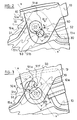
- These means are arranged on either side of the articulation zone of the collar 13 and are constituted respectively by a buttonhole 50 of axis of symmetry XX ′ (FIGS. 1 to 3) defined, on the one hand, by a segment of a hollowed-out circle 50a, the length of cord C of which is at least equal to the diameter D of the head 19a of the nail 19, and on the other hand, by a longitudinal slot 51, arranged symmetrically to the axis XX ' and opening through one of its ends 51a into the circle segment 50a and through its other end 51b into a circular opening 13a, the diameter D1 of which is at least equal to that of the projections 12a which engage therein.
- the longitudinal slot 50 is delimited transversely by lips 51c and 51d, elastically deformable out of their plane, during the introduction of the head 19a of neck 19.
- This introduction is carried out first by introducing in an inclined manner, one side of head 19a in the circle segment 50a, then by exerting lateral pressure on the collar 13, tending to deform the said lips out of their plane, and by passing the other part of the head 19a over the lips 51c, 51d which then resume their initial position, according to an original plane, behind the head 19a of the neck 19.
- the lips 51c and 51d also undergo another elastic deformation tending to separate them laterally, in the same plane this time, when the projection 12a passes in a direction F of introduction of the collar 13, and this until with elastic snap-fitting of said projection 12a in the cylindrical hole 13a.
- the diameter D1 of the hole 13a is greater than the width l of the slot 51, to define, near its entry 51b, two beads 52, 53 for retaining the collar 13 on the projection 12a.
- the longitudinal axis XX 'of the buttonhole forms an angle ⁇ relative to the generally vertical axis YY' of the collar 13, substantially equal to 45 ° but, of course, the axis XX 'of the buttonhole can be confused with the axis YY 'of the collar 13 or form a different angle ⁇ .
- the latter has a flared part formed by the ramp-shaped introduction edges 51e and 51j on the side of the end 51a of said slot 51 while the rest of the slot 51 has a substantially constant width l of value less than the diameter D1 of the projection 12a.
- the embodiment shown in FIG. 4 essentially differs from the previous one, in that the buttonhole 60 is defined by a circular hole 61 partially delimited on its periphery by two branches 62, 63 in the form of an annular sector forming jaws.
- the branches 62, 63 arise on the collar 13 itself, and are defined on the one hand by the hole 61 and on the other hand by a semicircular slot of larger diameter 69, and their free ends 62a and 63a are deformable out of their plan, to allow their engagement under the head 19a of the nail 19.
- the introduction of the head 19a of the nail 19 is carried out substantially as described above, by tilting a first part of the head 19a over a branch, 62 for example, then over the other 63 by a straightening gesture applied to said head.
- the free ends 62a, 63a delimit between them a passage 64 of width l1 less than the diameter D2 of the cylindrical hole 61 in which the projection or boss 12a engages during assembly in a direction F pour, to define at the entrance to said hole 61, two retaining beads 65 and 66.
- the free ends 62a and 63a form an angle such as to define a flared introduction part of width l2> l1.
- FIG. 5 differs essentially from that of Figure 4, in that a clearance J is provided between the outer periphery of the branches 62 and 63 in the form of an annular sector and the corresponding part of the collar 13 from which they originate by cutting, so as to give said branches 62, 63 a transverse elasticity in their plane.
- the mounting of the collar 13 on the head 19a is carried out as previously in a direction of engagement F2.
- the buttonhole 70 is defined by a circular hole 71 with a diameter D3 substantially equal to that of the projection 12a and partially delimited on its periphery by a tongue 72, arranged radially relative to the center O of the hole 71.
- the tongue 72 is delimited by lateral recesses, constituted here by grooves 73, 74 extended by cutouts 75, 76 able to make said tongue 72 elastically deformable out of its plane, this in order to allow the engagement of said buttonhole 70 on the head 19a of the nail 19, the passage of which in the hole 71 is made possible by driving the nail into the collar 13, which causes the tongue 72 to disappear from its plane, then its elastic return in its plane, behind the head 19a, thus resting on the entire surface surrounding the hole 71.
- the passage defined by the tongue 72 folded down with the opposite end of the hole 71 is at least equal to the diameter D3 of the head 19a of the nail 19.
- the embodiment shown in FIG. 7 essentially differs from the previous one in FIG. 6, in that the buttonhole 80 is of generally rectangular shape, the length L of which is substantially equal to the diameter of the head 19a of the nail 19, to allow its go to editing.
- the recess 81 is thus formed in a straight elastic tongue 83, elastically deformable out of its plane, thanks to two parallel lateral grooves 84 and 85.
- the tongue 83 is produced on one of the long sides of the rectangle, corresponding to the length L, while on the opposite side 86 is formed the recess 82, this side 86 therefore constituting a rigid bearing face.
- the head 19a initially bears by an inclined engagement, in the direction F5, then, by pivoting on itself by bending over said face 86, it overcomes the elastic force of the tab 83, to cause its erasure. After passage of the head 19a, the tongue naturally resumes its position in its plane, behind the said head 19a.
Landscapes
- Health & Medical Sciences (AREA)
- General Health & Medical Sciences (AREA)
- Physical Education & Sports Medicine (AREA)
- Footwear And Its Accessory, Manufacturing Method And Apparatuses (AREA)
Applications Claiming Priority (2)
| Application Number | Priority Date | Filing Date | Title |
|---|---|---|---|
| FR9013889 | 1990-11-06 | ||
| FR9013889A FR2668687B1 (fr) | 1990-11-06 | 1990-11-06 | Chaussure de sport notamment pour la marche et le ski de fond pourvue d'un collier amovible. |
Publications (2)
| Publication Number | Publication Date |
|---|---|
| EP0484683A1 true EP0484683A1 (de) | 1992-05-13 |
| EP0484683B1 EP0484683B1 (de) | 1995-01-04 |
Family
ID=9401996
Family Applications (1)
| Application Number | Title | Priority Date | Filing Date |
|---|---|---|---|
| EP91117102A Expired - Lifetime EP0484683B1 (de) | 1990-11-06 | 1991-10-08 | Sportschuh, insbesondere für Gehen und Skilanglauf, mit abnehmbarer Schaftmanschette |
Country Status (4)
| Country | Link |
|---|---|
| EP (1) | EP0484683B1 (de) |
| AT (1) | ATE116529T1 (de) |
| DE (1) | DE69106483T2 (de) |
| FR (1) | FR2668687B1 (de) |
Cited By (4)
| Publication number | Priority date | Publication date | Assignee | Title |
|---|---|---|---|---|
| EP0551881A1 (de) * | 1992-01-16 | 1993-07-21 | NORDICA S.p.A | Schuhwerk, insbesondere für Skifahren |
| FR2726976A1 (fr) * | 1994-11-17 | 1996-05-24 | Rossignol Sa | Chaussure de sport, notamment de marche ou de ski de fond |
| EP0917834A1 (de) * | 1997-11-24 | 1999-05-26 | Skis Rossignol S.A. | Langlauf-schischuh |
| WO2010049398A1 (en) * | 2008-10-29 | 2010-05-06 | Abe Sport Group S.R.L. | System for removably assembling a cuff on a sport boot, and sport boot provided with said system |
Families Citing this family (2)
| Publication number | Priority date | Publication date | Assignee | Title |
|---|---|---|---|---|
| DE102019003508A1 (de) * | 2019-05-20 | 2020-11-26 | Michael Henze | Zweiteiliger hoher Stiefel |
| CN116999785B (zh) * | 2023-08-25 | 2026-01-13 | 广州市勇源运动用品科技有限公司 | 可拆卸后护片快速互换装置 |
Citations (5)
| Publication number | Priority date | Publication date | Assignee | Title |
|---|---|---|---|---|
| FR2043998A5 (de) * | 1969-05-14 | 1971-02-19 | Rosaz Albert | |
| US4019267A (en) * | 1976-01-07 | 1977-04-26 | Dorofix Design Establishment | Ski boot structure |
| DE8807537U1 (de) * | 1987-12-21 | 1988-07-28 | Alpina Tovarna Obutve, n.sol.o., Žiri | Langlaufschuh |
| EP0416437A1 (de) * | 1989-09-07 | 1991-03-13 | Salomon S.A. | Langlaufskischuh |
| WO1991007889A1 (en) * | 1989-12-05 | 1991-06-13 | Alfa Skofabrik A/S | Device for cross-country ski boot |
-
1990
- 1990-11-06 FR FR9013889A patent/FR2668687B1/fr not_active Expired - Fee Related
-
1991
- 1991-10-08 EP EP91117102A patent/EP0484683B1/de not_active Expired - Lifetime
- 1991-10-08 AT AT91117102T patent/ATE116529T1/de not_active IP Right Cessation
- 1991-10-08 DE DE69106483T patent/DE69106483T2/de not_active Expired - Fee Related
Patent Citations (5)
| Publication number | Priority date | Publication date | Assignee | Title |
|---|---|---|---|---|
| FR2043998A5 (de) * | 1969-05-14 | 1971-02-19 | Rosaz Albert | |
| US4019267A (en) * | 1976-01-07 | 1977-04-26 | Dorofix Design Establishment | Ski boot structure |
| DE8807537U1 (de) * | 1987-12-21 | 1988-07-28 | Alpina Tovarna Obutve, n.sol.o., Žiri | Langlaufschuh |
| EP0416437A1 (de) * | 1989-09-07 | 1991-03-13 | Salomon S.A. | Langlaufskischuh |
| WO1991007889A1 (en) * | 1989-12-05 | 1991-06-13 | Alfa Skofabrik A/S | Device for cross-country ski boot |
Cited By (7)
| Publication number | Priority date | Publication date | Assignee | Title |
|---|---|---|---|---|
| EP0551881A1 (de) * | 1992-01-16 | 1993-07-21 | NORDICA S.p.A | Schuhwerk, insbesondere für Skifahren |
| US5381611A (en) * | 1992-01-16 | 1995-01-17 | Nordica S.P.A. | Footgear with replaceable flap elements |
| FR2726976A1 (fr) * | 1994-11-17 | 1996-05-24 | Rossignol Sa | Chaussure de sport, notamment de marche ou de ski de fond |
| EP0917834A1 (de) * | 1997-11-24 | 1999-05-26 | Skis Rossignol S.A. | Langlauf-schischuh |
| FR2771264A1 (fr) * | 1997-11-24 | 1999-05-28 | Rossignol Sa | Chaussure destinee a la pratique du ski de fond |
| US6098317A (en) * | 1997-11-24 | 2000-08-08 | Skis Rossignol S.A. | Boot intended for cross-country skiing |
| WO2010049398A1 (en) * | 2008-10-29 | 2010-05-06 | Abe Sport Group S.R.L. | System for removably assembling a cuff on a sport boot, and sport boot provided with said system |
Also Published As
| Publication number | Publication date |
|---|---|
| FR2668687B1 (fr) | 1992-12-31 |
| DE69106483D1 (de) | 1995-02-16 |
| EP0484683B1 (de) | 1995-01-04 |
| ATE116529T1 (de) | 1995-01-15 |
| FR2668687A1 (fr) | 1992-05-07 |
| DE69106483T2 (de) | 1995-05-11 |
Similar Documents
| Publication | Publication Date | Title |
|---|---|---|
| EP0088673B1 (de) | Vorrichtung für Langlaufski | |
| EP2060196B1 (de) | Schuh mit verbesserter Festziehmöglichkeit des Schafts | |
| CA2220989A1 (fr) | Chaussure de sport comportant un collier mobile | |
| WO1980001056A1 (fr) | Dispositif de fixation d'une chaussure sur une pedale de bicyclette | |
| FR2791230A1 (fr) | Languette de chaussure | |
| EP2580978A1 (de) | Boot with improved leg tightening | |
| EP2820966A1 (de) | Steigeisen für Schuh | |
| EP1688055A1 (de) | Sportschuh | |
| FR2583272A1 (fr) | Chaussure de ski alpin | |
| EP0620711B1 (de) | Langlaufschischuh und kombination von schi, bindung und schuh | |
| EP0230063B1 (de) | Verschlusseinrichtung für Sportschuh | |
| EP3108944A1 (de) | Schuhelement, das für die montage auf eine maschine bestimmt ist, und ausrüstung, die ein solches schuhelement und eine maschine umfasst | |
| EP2353417A1 (de) | Schuh mit verbesserter Sohle | |
| EP0484683B1 (de) | Sportschuh, insbesondere für Gehen und Skilanglauf, mit abnehmbarer Schaftmanschette | |
| CH678385A5 (de) | ||
| EP0514642B1 (de) | Langlauf-Skischuh | |
| EP0486801B1 (de) | Sportschuh, insbesondere zum Gehen und für den Skilanglauf, mit abnehmbarer hoher Schaftmanschette | |
| EP2885993B1 (de) | Sportschuh | |
| FR2544969A1 (fr) | Chaussure de ski | |
| EP2620071B1 (de) | Schuhelement, das mit einer verbesserten Einspannvorrichtung ausgestattet ist | |
| WO1993025107A1 (fr) | Chaussure avec dispositif de tenue de pied | |
| FR2722372A1 (fr) | Chaussure de sport, notamment chaussure de ski alpine | |
| FR2500314A1 (fr) | Talonniere pour fixations de ski de securite | |
| FR2848869A1 (fr) | Dispositif de retenue d'une chaussure sur un engin de sport | |
| EP0436444B1 (de) | Skischuh aus Kunststoff |
Legal Events
| Date | Code | Title | Description |
|---|---|---|---|
| PUAI | Public reference made under article 153(3) epc to a published international application that has entered the european phase |
Free format text: ORIGINAL CODE: 0009012 |
|
| AK | Designated contracting states |
Kind code of ref document: A1 Designated state(s): AT CH DE IT LI |
|
| 17P | Request for examination filed |
Effective date: 19921105 |
|
| 17Q | First examination report despatched |
Effective date: 19921229 |
|
| GRAA | (expected) grant |
Free format text: ORIGINAL CODE: 0009210 |
|
| ITF | It: translation for a ep patent filed | ||
| AK | Designated contracting states |
Kind code of ref document: B1 Designated state(s): AT CH DE IT LI |
|
| REF | Corresponds to: |
Ref document number: 116529 Country of ref document: AT Date of ref document: 19950115 Kind code of ref document: T |
|
| REF | Corresponds to: |
Ref document number: 69106483 Country of ref document: DE Date of ref document: 19950216 |
|
| PLBE | No opposition filed within time limit |
Free format text: ORIGINAL CODE: 0009261 |
|
| STAA | Information on the status of an ep patent application or granted ep patent |
Free format text: STATUS: NO OPPOSITION FILED WITHIN TIME LIMIT |
|
| 26N | No opposition filed | ||
| PGFP | Annual fee paid to national office [announced via postgrant information from national office to epo] |
Ref country code: CH Payment date: 19961227 Year of fee payment: 6 |
|
| PG25 | Lapsed in a contracting state [announced via postgrant information from national office to epo] |
Ref country code: LI Free format text: LAPSE BECAUSE OF NON-PAYMENT OF DUE FEES Effective date: 19971031 Ref country code: CH Free format text: LAPSE BECAUSE OF NON-PAYMENT OF DUE FEES Effective date: 19971031 |
|
| REG | Reference to a national code |
Ref country code: CH Ref legal event code: PL |
|
| PGFP | Annual fee paid to national office [announced via postgrant information from national office to epo] |
Ref country code: AT Payment date: 20001010 Year of fee payment: 10 |
|
| PGFP | Annual fee paid to national office [announced via postgrant information from national office to epo] |
Ref country code: DE Payment date: 20001127 Year of fee payment: 10 |
|
| PG25 | Lapsed in a contracting state [announced via postgrant information from national office to epo] |
Ref country code: AT Free format text: LAPSE BECAUSE OF NON-PAYMENT OF DUE FEES Effective date: 20011008 |
|
| PG25 | Lapsed in a contracting state [announced via postgrant information from national office to epo] |
Ref country code: DE Free format text: LAPSE BECAUSE OF NON-PAYMENT OF DUE FEES Effective date: 20020702 |
|
| PG25 | Lapsed in a contracting state [announced via postgrant information from national office to epo] |
Ref country code: IT Free format text: LAPSE BECAUSE OF NON-PAYMENT OF DUE FEES;WARNING: LAPSES OF ITALIAN PATENTS WITH EFFECTIVE DATE BEFORE 2007 MAY HAVE OCCURRED AT ANY TIME BEFORE 2007. THE CORRECT EFFECTIVE DATE MAY BE DIFFERENT FROM THE ONE RECORDED. Effective date: 20051008 |