EP0484602B1 - Rad mit einem Luftreifen mit schwenkbaren Grundkörpern - Google Patents
Rad mit einem Luftreifen mit schwenkbaren Grundkörpern Download PDFInfo
- Publication number
- EP0484602B1 EP0484602B1 EP90312267A EP90312267A EP0484602B1 EP 0484602 B1 EP0484602 B1 EP 0484602B1 EP 90312267 A EP90312267 A EP 90312267A EP 90312267 A EP90312267 A EP 90312267A EP 0484602 B1 EP0484602 B1 EP 0484602B1
- Authority
- EP
- European Patent Office
- Prior art keywords
- tyre
- pad
- spindle
- ground
- pads
- Prior art date
- Legal status (The legal status is an assumption and is not a legal conclusion. Google has not performed a legal analysis and makes no representation as to the accuracy of the status listed.)
- Expired - Lifetime
Links
- 230000008878 coupling Effects 0.000 claims description 7
- 238000010168 coupling process Methods 0.000 claims description 7
- 238000005859 coupling reaction Methods 0.000 claims description 7
- 238000006073 displacement reaction Methods 0.000 claims description 5
- 239000012858 resilient material Substances 0.000 claims description 2
- 230000001419 dependent effect Effects 0.000 claims 1
- 230000008901 benefit Effects 0.000 description 4
- 244000025254 Cannabis sativa Species 0.000 description 2
- 239000004677 Nylon Substances 0.000 description 2
- 229920001778 nylon Polymers 0.000 description 2
- 238000005056 compaction Methods 0.000 description 1
- 238000010276 construction Methods 0.000 description 1
- 239000013013 elastic material Substances 0.000 description 1
- 239000000835 fiber Substances 0.000 description 1
- 235000000396 iron Nutrition 0.000 description 1
- 238000010068 moulding (rubber) Methods 0.000 description 1
- 239000012779 reinforcing material Substances 0.000 description 1
Images


Classifications
-
- B—PERFORMING OPERATIONS; TRANSPORTING
- B60—VEHICLES IN GENERAL
- B60C—VEHICLE TYRES; TYRE INFLATION; TYRE CHANGING; CONNECTING VALVES TO INFLATABLE ELASTIC BODIES IN GENERAL; DEVICES OR ARRANGEMENTS RELATED TO TYRES
- B60C11/00—Tyre tread bands; Tread patterns; Anti-skid inserts
- B60C11/02—Replaceable treads
-
- B—PERFORMING OPERATIONS; TRANSPORTING
- B60—VEHICLES IN GENERAL
- B60B—VEHICLE WHEELS; CASTORS; AXLES FOR WHEELS OR CASTORS; INCREASING WHEEL ADHESION
- B60B15/00—Wheels or wheel attachments designed for increasing traction
- B60B15/18—Wheels with ground-engaging plate-like shoes
-
- B—PERFORMING OPERATIONS; TRANSPORTING
- B60—VEHICLES IN GENERAL
- B60C—VEHICLE TYRES; TYRE INFLATION; TYRE CHANGING; CONNECTING VALVES TO INFLATABLE ELASTIC BODIES IN GENERAL; DEVICES OR ARRANGEMENTS RELATED TO TYRES
- B60C27/00—Non-skid devices temporarily attachable to resilient tyres or resiliently-tyred wheels
- B60C27/20—Non-skid devices temporarily attachable to resilient tyres or resiliently-tyred wheels having ground-engaging plate-like elements
Definitions
- the invention relates to wheels for machines which normally require wide faced tyres for the purpose of spreading the load carried over grass covered ground or other soft surfaces, for example, golf fairways and has particular, though not exclusive,application to wheels for use on golf carts, grass mowing machines and other mobile apparatus.
- Patent Specification US-A-1 600 589 discloses a traction device corresponding to the preamble of claim 1 wherein a double tread wheel has shoes disposed about its periphery, the shoes comprising channel irons each secured to a peripherally extending cable located between the treads and the treads being formed of elastic material so as frictionally to support the shoes but to allow the shoes to creep around the wheel.
- a tyre for mounting on a wheel hub, the tyre having a plurality of ground engaging pads disposed around the periphery of the tyre, with each pad being capable of at least a limited degree of angular displacement,
- the tyre is a pneumatic tyre
- the limited degree of angular displacement is about a radial axis relative to the tyre, whereby the tyre may turn through the said limited angle relative to any pad currently in ground contact, and means are provided for returning each pad to its undisplaced position when the pad has moved out of contact with the ground.
- the tyre is preferably mounted on a conventional wheel hub, and a conventional tube is provided to inflate the tyre to the correct pressure.
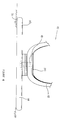
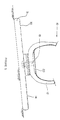
- the wheel 10 comprises a rigid hub 11 having mounted thereon a pneumatic tyre 12.
- the tyre 12 incorporates a conventional inflatable tube 13, which when inflated pressurises the tyre to an appropriate pressure.
- a plurality of ground engaging pads 14 are disposed around and coupled to the periphery 15 of the tyre 12.
- Each pad which is of a resilient material, for example rubber, is of a width of approximately 355 mm (14 inches) and of a length in the direction of rotation of the tyre of approximately 127 mm (5 inches). As shown, the pads 14 are slightly spaced apart and taper from their widest central part 16 towards the ends 17.
- the pads 14 are coupled to the periphery of the tyre 12 by a coupling means, as will now be described, so as to permit each pad at least a limited degree of angular displacement about a notional radial axis relative to the tyre 12.
- the coupling means comprises a spindle 18 which passes through an aperture 19 in the tyre 12.
- the spindle 18 has a plate member 20 fixed at its end 21, the plate member 20 engaging the inner surface 22 of the tyre to locate the spindle 18 in position.
- a rubber washer 23 is fixed to the outer surface 24 of the tyre in the region of the aperture 19.
- a locking plate 25 is located on the spindle 18 adjacent to the rubber washer 23, and a locking nut 26 engages with suitable screw-threads 27 on the spindle 18, to securely lock the spindle 18 to the tyre 12.
- a nylon bearing plate 28 is located over the locking nut 26, the aperture 29 in the bearing plate 28 into which the locking nut 26 is received being of a greater diameter than the diameter of the locking nut 26.
- the ground engaging pad 14 comprises a base plate 30 on which is fixed a rubber block 31 having a square shaped aperture 32.
- the base plate 30 has a circular aperture 33 through which a shoulder portion 34 of the spindle 18 engages.
- the aperture 33 is very slightly greater in diameter than the diameter of the shoulder portion 34 of the spindle 18, so that the pad 14 can turn freely relative to the spindle 18.
- the free end 35 of the spindle 18 is formed as a square shape and the pad 14 is secured on the spindle 18 by means of a square shaped retaining block 36 which is held in place by a suitable circlip 37 secured to the spindle 18 as shown.
- the retaining block 36 is located on the spindle 18 within the region of the squared shaped aperture 32 in the rubber block 31.
- the retaining block 36 is of a diameter slightly less than that of the aperture 32.
- the spindle 18 serves only the purpose of coupling the pads 14 to the tyre 12.
- the pads 14 carry the weight which is transferred to the tyre 12, by the pad 14 pressing against the nylon plate 28 which in turn presses against the outer surface 24 of the tyre 12.
- the pad When the tyre 12 is turned relative to that one of the pads 14 which is in contact with the ground surface, the pad will remain stationary and the tyre 12 and spindle 18 including the retaining block 36, will rotate a predetermined angular distance approximately 4 to 15°. As the retaining block 36 rotates, it will engage and compress the walls of the rubber block 31 which define the aperture 32. Thus, the rubber block 31 in the region of the aperture 32 will be compressed and the relative angular movement of the tyre will be determined, by the degree of resilience of the rubber block 31 and by how long the pad 14 remains in ground contact. Once the pad 14 moves out of ground contact, the resilience of the rubber block 31 causes the pad 14 to return to its normal position. As described previously, the pads 14 are tapered to facilitate relative turning of the pads.
- expansion springs may be used one fixed at one side of each pad 14 with the other end of each spring fixed to the hub 11 of the wheel. This will enable the pads to be returned to their undisplaced position.
- the invention provides a construction of wheel and tyre which enables the substantial reduction of ground compaction by spreading the weight carried over a greater area being that of the pads 14 which provide a very much larger area than that of the typical tyre.
- the pressure exerted by the pads on the ground surface is substantially less than that exerted by convention wide faced tyres.
- this wheel can turn without damage to the ground surface because the pads 14 remain stationary on the ground surface while the wheel itself turns. The damage to the ground surfaces caused by wheels turning on sloping ground surfaces is also mitigated because the pads 14 will always remain flat on the ground surface as shown in Figure 5.
- the invention maintains the advantage of pneumatic tyres being that of air cushioning.
- the entire circumference of the tyre is covered by a one piece sleeve of flexible rubber which is attached by known means, for example vulcanising to each base plate 30.
- the rubber sleeve would have a number of spaced apart slots, with the space between each adjacent pair or slots defining a recess for a pad. This arrangement would have a continuous central rubber area with the necessary flexibility to provide a smooth running revolution of the wheel.
- another embodiment of the invention provides a pneumatic tyre having flexible rubber mountings integrally formed with and protruding from its ground engaging surface.
- the ground engaging pads are attached to the rubber mountings.
- Such a flexible mounting would allow the hub of the wheel to turn at ground contact and return the pad to its undisplaced position as soon as it comes off ground pressure.
- rubber blocks for example car engine mounting blocks could be secured to the tyre with the mounting block also fixed to the base plate of the pads.
- All the novelty and benefits of the invention may be maintained by having the combination of pneumatic tyre and pads manufactured as a single unit rubber moulding. This would eliminate the necessity for the mechanical linkage between the pads and the tyre. The inherent flexibility of the rubber would allow the pads to twist to the necessary extent thereby eliminating the need for the mechanical means of returning the pad to its undisplaced position after each pad rolls off ground contact. The flexibility of the relatively narrow region of pad in direct contact with the tyre surface, would allow the hub of the wheel to turn without causing the pad to slide at ground contact when it takes the weight of the machine. Fibre or other known reinforcing material could be moulded (or inserted) with the tyre so as to strengthen the wide cross section area of each pad.
- the tyre cannot wear out, or be punctured; the pads are replaceable without having to deflate the tyre; the size of the pads can be selected to suit the size of the wheel; the tyre may or may not be tubeless.
Landscapes
- Engineering & Computer Science (AREA)
- Mechanical Engineering (AREA)
- Tires In General (AREA)
Claims (8)
- Reifen (12) zur Anbringung auf einer Radnabe (11), wobei der Reifen (12) eine Mehrzahl von rings des Umfangs (15) des Reifens angeordneten Bodenangriffsplatten (14) aufweist, wobei jede Platte (14) wenigstens begrenzt im Winkel verstellbar ist, dadurch gekennzeichnet, daß der Reifen (12) ein Luftreifen ist und die begrenzte Winkelverstellbarkeit um eine radiale Achse relativ zu dem Reifen (12) gegeben ist, wodurch der Reifen um den begrenzten Winkel retativ zu der jeweiligen im Bodenkontakt befindlichen Platte sich drehen kann, und daß Mittel (31, 36) zum Zurückstellen der jeweiligen Platte (14) in die Ausgangsstellung nach der Bewegung der Platte außer Kontakt mit dem Boden vorgesehen sind.
- Reifen nach Anspruch 1, wobei eine Kupplungseinrichtung (18) zum Kuppeln jeder Platte (14) an den Umfang (15) des Reifens vorgesehen ist.
- Reifen nach Anspruch 2, wobei die Kupplungseinrichtung eine Spindel (18) aufweist, die durch ein Loch (19) in dem Reifen (12) vorsteht, wobei die Spindel ein an dem einen Ende festgelegtes Plattenglied (20) aufweist, das an der Innenfläche des Reifens angreift, und das freie Ende (35) der Spindel an einer Bodenangriffsplatte angeschlossen ist.
- Reifen nach einem der Ansprüche 1 bis 3, bei welchem jede Bodenangriffsplatte (14) eine Grundplatte (30) aufweist, an der ein Stollen (31) aus federnd nachgiebigem Materiat befestigt ist.
- Reifen nach Anspruch 3 oder 4, wobei das freie Ende (35) der Spindel (18) durch ein Loch (33) in der Grundplatte (30) und in eine Ausnehmung (32) in dem federnd nachgiebigen Stollen (31) ragt und ein Halteglied (36) an dem freien Ende (35) der Spindel (18) befestigt ist.
- Reifen nach Anspruch 6, wobei das Halteglied (36) derart in den federnd nachgiebigen Stollen (31) eingreift, daß wenn sich der Reifen (12) dreht, das Halteglied (36) der in Bodentakt befindlichen Platte (14) den federnd nachgiebigen Stollen zusammendrückt, und wenn dieser Stollen außer Bodenkontakt getangt, die inhärente Elastizität des federnd nachgiebigen Stollens (31) die Platte (14) veranlaßt, in die Normalposition zurückzukehren.
- Reifen nach einem der vorstehenden Ansprüche, bei welchem die an dem Boden angreifenden Platten (14) etwas voneinander entfernt sind und sich von ihrem breitesten Mittelteil (19) zu den Enden (17) hin verjüngen.
Priority Applications (2)
| Application Number | Priority Date | Filing Date | Title |
|---|---|---|---|
| AT90312267T ATE92853T1 (de) | 1990-11-09 | 1990-11-09 | Rad mit einem luftreifen mit schwenkbaren grundkoerpern. |
| DE1990602768 DE69002768T2 (de) | 1990-11-09 | 1990-11-09 | Rad mit einem Luftreifen mit schwenkbaren Grundkörpern. |
Applications Claiming Priority (1)
| Application Number | Priority Date | Filing Date | Title |
|---|---|---|---|
| IE383588 | 1988-12-21 |
Publications (2)
| Publication Number | Publication Date |
|---|---|
| EP0484602A1 EP0484602A1 (de) | 1992-05-13 |
| EP0484602B1 true EP0484602B1 (de) | 1993-08-11 |
Family
ID=11039127
Family Applications (1)
| Application Number | Title | Priority Date | Filing Date |
|---|---|---|---|
| EP90312267A Expired - Lifetime EP0484602B1 (de) | 1988-12-21 | 1990-11-09 | Rad mit einem Luftreifen mit schwenkbaren Grundkörpern |
Country Status (2)
| Country | Link |
|---|---|
| US (1) | US5004030A (de) |
| EP (1) | EP0484602B1 (de) |
Families Citing this family (13)
| Publication number | Priority date | Publication date | Assignee | Title |
|---|---|---|---|---|
| GB9514550D0 (en) * | 1995-07-10 | 1995-09-13 | Elite Golf Products Limited | Wheels and tyres |
| US6443466B2 (en) | 1998-12-16 | 2002-09-03 | Carl-All, Inc. | All-terrain bicycle |
| GB0004524D0 (en) * | 2000-02-26 | 2000-04-19 | Argent John D | Wheel attachment |
| KR100478371B1 (ko) * | 2003-01-09 | 2005-03-24 | 김서림 | 계단, 경사로, 험로 주행장치 |
| US7198084B2 (en) * | 2004-08-06 | 2007-04-03 | Marilyn Tiffany Riemer | Dual purpose tire wrap |
| US8714278B2 (en) * | 2005-07-01 | 2014-05-06 | Simba International Limited | Soil treatment apparatus, a soil treatment component and a method of assembling a soil treatment apparatus |
| US20070023117A1 (en) * | 2005-07-26 | 2007-02-01 | Seamus Mclaughlin | Tyre with pivotable ground pads |
| US20130062841A1 (en) * | 2011-09-14 | 2013-03-14 | James K. Bullis | Off-road vehicle |
| US9211922B2 (en) * | 2012-08-17 | 2015-12-15 | Cardinal Gibbons High School | Robotic vehicle having traction and mobility-enhanced wheel structures |
| US10179476B2 (en) | 2012-10-29 | 2019-01-15 | Karsten Manufacturing Corporation | Collapsible wheels and methods of making collapsible wheels |
| US12017477B2 (en) | 2012-10-29 | 2024-06-25 | Karsten Manufacturing Corporation | Collapsible wheels and methods of making collapsible wheels |
| CN105856987B (zh) * | 2016-04-11 | 2018-06-05 | 葛强林 | 一种雪橇式车轮防滑陷卡板 |
| US11241908B2 (en) * | 2018-05-01 | 2022-02-08 | Nicholas E. Mansfield | Flex track |
Family Cites Families (9)
| Publication number | Priority date | Publication date | Assignee | Title |
|---|---|---|---|---|
| FR607205A (de) * | 1926-06-28 | |||
| US1090851A (en) * | 1914-01-08 | 1914-03-24 | Sterling C Munson | Metal tread for block-tires. |
| GB241742A (en) * | 1924-12-01 | 1925-10-29 | Henry Mclaren | Improvements in, or connected with, traction wheels |
| US1600589A (en) * | 1925-03-21 | 1926-09-21 | L C Harward | Traction device |
| US2552995A (en) * | 1948-07-24 | 1951-05-15 | Joseph A Morrone | Combined vehicle tire and antiskid device therefor |
| US3344832A (en) * | 1965-09-08 | 1967-10-03 | Horne Alfred | Pneumatic tire |
| US3871720A (en) * | 1973-07-31 | 1975-03-18 | Uniroyal Inc | Traction tread band |
| SU1320113A1 (ru) * | 1985-06-28 | 1987-06-30 | Ухтинский индустриальный институт | Гусенична цепь транспортного средства |
| SU1416363A2 (ru) * | 1987-01-19 | 1988-08-15 | Всесоюзный научно-исследовательский институт торфяной промышленности | Гусеница |
-
1989
- 1989-12-21 US US07/454,591 patent/US5004030A/en not_active Expired - Fee Related
-
1990
- 1990-11-09 EP EP90312267A patent/EP0484602B1/de not_active Expired - Lifetime
Also Published As
| Publication number | Publication date |
|---|---|
| US5004030A (en) | 1991-04-02 |
| EP0484602A1 (de) | 1992-05-13 |
Similar Documents
| Publication | Publication Date | Title |
|---|---|---|
| US5004030A (en) | Pneumatic tire with pivotable ground pads | |
| EP2066502B1 (de) | Speicher von variabler festigkeit für eine nichtpneumatische baugruppe | |
| KR101059722B1 (ko) | 컴플라이언트 휠 | |
| US4235270A (en) | Tire with supporting and cushioning walls | |
| JP4601099B2 (ja) | 空気入りタイヤ用の非装着式監視用組立体 | |
| US4461333A (en) | Internal support to resist the flattening of a tire | |
| US4124051A (en) | Shock absorbing wheel hub | |
| KR890002974B1 (ko) | 차륜 | |
| JPH01314603A (ja) | 非空気式タイヤ | |
| CA1314468C (en) | Crossband device to be attached on tire on snowy road | |
| CA2272108C (en) | Durable, smooth ride wheel and solid rubber tire | |
| US3747658A (en) | Flexible sectional wheel | |
| CA2038455A1 (en) | Pneumatic tyre wheel with pivotable ground pads | |
| CA1135164A (en) | Tubeless pneumatic tires | |
| EP0780245A3 (de) | Luftreifen | |
| CA1138313A (en) | Tire with supportable sidewalls | |
| US20060076096A1 (en) | Wheel and tire assembly for recreational vehicles | |
| CN217435423U (zh) | 一种滚动阻力小的汽车轮胎 | |
| US2941565A (en) | Safety tire for motor vehicle wheels | |
| CA2176279A1 (en) | Low pressure all terrain vehicle tire | |
| JPH04176719A (ja) | 旋回式路面パッド付き空気タイヤ | |
| US4685743A (en) | Wheel anti-skid attachment | |
| KR102437390B1 (ko) | 비공기압 타이어 | |
| CA1112550A (en) | Bicycle tire with compression amplification | |
| JP2022089778A (ja) | 支持構造体のためのホイール |
Legal Events
| Date | Code | Title | Description |
|---|---|---|---|
| PUAI | Public reference made under article 153(3) epc to a published international application that has entered the european phase |
Free format text: ORIGINAL CODE: 0009012 |
|
| 17P | Request for examination filed |
Effective date: 19920225 |
|
| AK | Designated contracting states |
Kind code of ref document: A1 Designated state(s): AT BE CH DE DK ES FR GB GR IT LI LU NL SE |
|
| 17Q | First examination report despatched |
Effective date: 19920805 |
|
| GRAA | (expected) grant |
Free format text: ORIGINAL CODE: 0009210 |
|
| AK | Designated contracting states |
Kind code of ref document: B1 Designated state(s): AT BE CH DE DK ES FR GB GR IT LI LU NL SE |
|
| PG25 | Lapsed in a contracting state [announced via postgrant information from national office to epo] |
Ref country code: IT Free format text: LAPSE BECAUSE OF FAILURE TO SUBMIT A TRANSLATION OF THE DESCRIPTION OR TO PAY THE FEE WITHIN THE PRESCRIBED TIME-LIMIT;WARNING: LAPSES OF ITALIAN PATENTS WITH EFFECTIVE DATE BEFORE 2007 MAY HAVE OCCURRED AT ANY TIME BEFORE 2007. THE CORRECT EFFECTIVE DATE MAY BE DIFFERENT FROM THE ONE RECORDED. Effective date: 19930811 Ref country code: LI Effective date: 19930811 Ref country code: GR Free format text: LAPSE BECAUSE OF FAILURE TO SUBMIT A TRANSLATION OF THE DESCRIPTION OR TO PAY THE FEE WITHIN THE PRESCRIBED TIME-LIMIT Effective date: 19930811 Ref country code: ES Free format text: THE PATENT HAS BEEN ANNULLED BY A DECISION OF A NATIONAL AUTHORITY Effective date: 19930811 Ref country code: DK Effective date: 19930811 Ref country code: BE Effective date: 19930811 Ref country code: AT Effective date: 19930811 Ref country code: CH Effective date: 19930811 Ref country code: NL Effective date: 19930811 |
|
| REF | Corresponds to: |
Ref document number: 92853 Country of ref document: AT Date of ref document: 19930815 Kind code of ref document: T |
|
| REF | Corresponds to: |
Ref document number: 69002768 Country of ref document: DE Date of ref document: 19930916 |
|
| REG | Reference to a national code |
Ref country code: CH Ref legal event code: PL |
|
| PG25 | Lapsed in a contracting state [announced via postgrant information from national office to epo] |
Ref country code: LU Free format text: LAPSE BECAUSE OF NON-PAYMENT OF DUE FEES Effective date: 19931130 |
|
| ET | Fr: translation filed | ||
| NLV1 | Nl: lapsed or annulled due to failure to fulfill the requirements of art. 29p and 29m of the patents act | ||
| PGFP | Annual fee paid to national office [announced via postgrant information from national office to epo] |
Ref country code: FR Payment date: 19940127 Year of fee payment: 4 |
|
| PGFP | Annual fee paid to national office [announced via postgrant information from national office to epo] |
Ref country code: DE Payment date: 19940131 Year of fee payment: 4 |
|
| PGFP | Annual fee paid to national office [announced via postgrant information from national office to epo] |
Ref country code: SE Payment date: 19940207 Year of fee payment: 4 |
|
| PLBE | No opposition filed within time limit |
Free format text: ORIGINAL CODE: 0009261 |
|
| STAA | Information on the status of an ep patent application or granted ep patent |
Free format text: STATUS: NO OPPOSITION FILED WITHIN TIME LIMIT |
|
| 26N | No opposition filed | ||
| PG25 | Lapsed in a contracting state [announced via postgrant information from national office to epo] |
Ref country code: SE Effective date: 19941110 |
|
| EAL | Se: european patent in force in sweden |
Ref document number: 90312267.9 |
|
| PG25 | Lapsed in a contracting state [announced via postgrant information from national office to epo] |
Ref country code: FR Effective date: 19950731 |
|
| PG25 | Lapsed in a contracting state [announced via postgrant information from national office to epo] |
Ref country code: DE Effective date: 19950801 |
|
| EUG | Se: european patent has lapsed |
Ref document number: 90312267.9 |
|
| REG | Reference to a national code |
Ref country code: FR Ref legal event code: ST |
|
| REG | Reference to a national code |
Ref country code: GB Ref legal event code: IF02 |
|
| PGFP | Annual fee paid to national office [announced via postgrant information from national office to epo] |
Ref country code: GB Payment date: 20030509 Year of fee payment: 13 |
|
| PG25 | Lapsed in a contracting state [announced via postgrant information from national office to epo] |
Ref country code: GB Free format text: LAPSE BECAUSE OF NON-PAYMENT OF DUE FEES Effective date: 20031109 |
|
| GBPC | Gb: european patent ceased through non-payment of renewal fee |
Effective date: 20031109 |