EP0484430B1 - Szintillationsvorrichtung zur messung der signalabschwächung mit hilfe von transmissionstomographie - Google Patents
Szintillationsvorrichtung zur messung der signalabschwächung mit hilfe von transmissionstomographie Download PDFInfo
- Publication number
- EP0484430B1 EP0484430B1 EP90912241A EP90912241A EP0484430B1 EP 0484430 B1 EP0484430 B1 EP 0484430B1 EP 90912241 A EP90912241 A EP 90912241A EP 90912241 A EP90912241 A EP 90912241A EP 0484430 B1 EP0484430 B1 EP 0484430B1
- Authority
- EP
- European Patent Office
- Prior art keywords
- detector
- gamma camera
- accordance
- fact
- gamma
- Prior art date
- Legal status (The legal status is an assumption and is not a legal conclusion. Google has not performed a legal analysis and makes no representation as to the accuracy of the status listed.)
- Expired - Lifetime
Links
- 230000005540 biological transmission Effects 0.000 title claims description 11
- 238000003325 tomography Methods 0.000 title description 13
- 230000002285 radioactive effect Effects 0.000 claims abstract description 23
- 230000033001 locomotion Effects 0.000 claims description 4
- 238000012545 processing Methods 0.000 claims description 4
- 230000005251 gamma ray Effects 0.000 claims description 3
- 230000005855 radiation Effects 0.000 abstract description 18
- 230000000694 effects Effects 0.000 abstract description 7
- 238000000034 method Methods 0.000 description 10
- 238000001514 detection method Methods 0.000 description 8
- 238000012937 correction Methods 0.000 description 5
- 238000005259 measurement Methods 0.000 description 5
- 239000007788 liquid Substances 0.000 description 4
- 238000010606 normalization Methods 0.000 description 4
- 239000003550 marker Substances 0.000 description 3
- 229920003023 plastic Polymers 0.000 description 3
- 230000008707 rearrangement Effects 0.000 description 3
- 210000001015 abdomen Anatomy 0.000 description 2
- 238000010521 absorption reaction Methods 0.000 description 2
- 238000004364 calculation method Methods 0.000 description 2
- 239000013078 crystal Substances 0.000 description 2
- 239000012895 dilution Substances 0.000 description 2
- 238000010790 dilution Methods 0.000 description 2
- 239000012530 fluid Substances 0.000 description 2
- 210000000245 forearm Anatomy 0.000 description 2
- 230000005484 gravity Effects 0.000 description 2
- 230000001681 protective effect Effects 0.000 description 2
- 208000031968 Cadaver Diseases 0.000 description 1
- 230000004075 alteration Effects 0.000 description 1
- 238000004873 anchoring Methods 0.000 description 1
- 238000013459 approach Methods 0.000 description 1
- 239000008280 blood Substances 0.000 description 1
- 210000004369 blood Anatomy 0.000 description 1
- 238000005056 compaction Methods 0.000 description 1
- 238000002591 computed tomography Methods 0.000 description 1
- 230000001419 dependent effect Effects 0.000 description 1
- 238000011161 development Methods 0.000 description 1
- 238000002059 diagnostic imaging Methods 0.000 description 1
- 239000006185 dispersion Substances 0.000 description 1
- 239000000428 dust Substances 0.000 description 1
- 239000011521 glass Substances 0.000 description 1
- 238000003384 imaging method Methods 0.000 description 1
- 238000002347 injection Methods 0.000 description 1
- 239000007924 injection Substances 0.000 description 1
- 230000003993 interaction Effects 0.000 description 1
- 210000004185 liver Anatomy 0.000 description 1
- 230000004807 localization Effects 0.000 description 1
- 239000000463 material Substances 0.000 description 1
- 235000012771 pancakes Nutrition 0.000 description 1
- 230000003389 potentiating effect Effects 0.000 description 1
- 229920006395 saturated elastomer Polymers 0.000 description 1
- 230000035945 sensitivity Effects 0.000 description 1
- 238000002603 single-photon emission computed tomography Methods 0.000 description 1
- 239000000243 solution Substances 0.000 description 1
- 239000010421 standard material Substances 0.000 description 1
- 229910052713 technetium Inorganic materials 0.000 description 1
- GKLVYJBZJHMRIY-UHFFFAOYSA-N technetium atom Chemical compound [Tc] GKLVYJBZJHMRIY-UHFFFAOYSA-N 0.000 description 1
Images
Classifications
-
- G—PHYSICS
- G01—MEASURING; TESTING
- G01T—MEASUREMENT OF NUCLEAR OR X-RADIATION
- G01T1/00—Measuring X-radiation, gamma radiation, corpuscular radiation, or cosmic radiation
- G01T1/16—Measuring radiation intensity
- G01T1/161—Applications in the field of nuclear medicine, e.g. in vivo counting
- G01T1/164—Scintigraphy
- G01T1/1641—Static instruments for imaging the distribution of radioactivity in one or two dimensions using one or several scintillating elements; Radio-isotope cameras
- G01T1/1642—Static instruments for imaging the distribution of radioactivity in one or two dimensions using one or several scintillating elements; Radio-isotope cameras using a scintillation crystal and position sensing photodetector arrays, e.g. ANGER cameras
-
- A—HUMAN NECESSITIES
- A61—MEDICAL OR VETERINARY SCIENCE; HYGIENE
- A61B—DIAGNOSIS; SURGERY; IDENTIFICATION
- A61B6/00—Apparatus or devices for radiation diagnosis; Apparatus or devices for radiation diagnosis combined with radiation therapy equipment
- A61B6/42—Arrangements for detecting radiation specially adapted for radiation diagnosis
- A61B6/4208—Arrangements for detecting radiation specially adapted for radiation diagnosis characterised by using a particular type of detector
- A61B6/4258—Arrangements for detecting radiation specially adapted for radiation diagnosis characterised by using a particular type of detector for detecting non x-ray radiation, e.g. gamma radiation
-
- G—PHYSICS
- G01—MEASURING; TESTING
- G01T—MEASUREMENT OF NUCLEAR OR X-RADIATION
- G01T1/00—Measuring X-radiation, gamma radiation, corpuscular radiation, or cosmic radiation
- G01T1/16—Measuring radiation intensity
- G01T1/161—Applications in the field of nuclear medicine, e.g. in vivo counting
- G01T1/164—Scintigraphy
- G01T1/1641—Static instruments for imaging the distribution of radioactivity in one or two dimensions using one or several scintillating elements; Radio-isotope cameras
- G01T1/1648—Ancillary equipment for scintillation cameras, e.g. reference markers, devices for removing motion artifacts, calibration devices
-
- A—HUMAN NECESSITIES
- A61—MEDICAL OR VETERINARY SCIENCE; HYGIENE
- A61B—DIAGNOSIS; SURGERY; IDENTIFICATION
- A61B6/00—Apparatus or devices for radiation diagnosis; Apparatus or devices for radiation diagnosis combined with radiation therapy equipment
- A61B6/02—Arrangements for diagnosis sequentially in different planes; Stereoscopic radiation diagnosis
- A61B6/03—Computed tomography [CT]
- A61B6/037—Emission tomography
Definitions
- the present invention relates to a scintillation device usable for measuring attenuation by transmission tomography. It finds its application more particularly in the medical field where, in association with a gamma camera conventionally used, it makes it possible to refine the knowledge of the internal structures revealed by an examination of tomography in emission executed by means of this gamma camera.
- An emission tomography examination carried out by means of a gamma camera involves the injection, into a body to be examined, of a radioactive marker.
- the marker for example Technetium
- the radioactive marker is injected, in the form of a dilution, into the patient's blood.
- the radioactive marker produces a measurable radioactive phenomenon.
- the radioactive phenomenon essentially involves the emission of gamma rays.
- a gamma camera essentially comprises a stand to support a detector surmounted by the scintillator crystal.
- a gamma camera also includes a control and processing console.
- the detector includes an arrangement of photomultiplier tubes to produce electrical signals corresponding to detected scintillations.
- the scintillator absorbs radioactive gamma radiation by photoelectric effect. It emits a light scintillation detected downstream by the network detector photomultiplier tubes.
- the tubes are associated with calculation means. These make it possible to determine the coordinates of a place of interaction of gamma radiation in the scintillator.
- this localization can only be achieved by interposing a collimator between the body and the scintillator. This collimator only lets through radioactive radiation in a chosen direction.
- This technique has two drawbacks, however. First, move the patient from one machine to another. We can never be sure that it will resume in the second machine the same position as it had in the first. The measures become difficult to compare or transpose. On the other hand, the energies of the radiation used in one case and in the other are different. These are X-rays in computed tomography and they are gamma rays in the scintillation device, and the measured attenuation coefficients are all dependent on the energy of the radiation absorbed.
- the object of the invention is to remedy these drawbacks by nevertheless using a point source arranged in correspondence and close to the gamma camera.
- the proximity is less than 1 meter: in a preferred example it is 70 cm.
- a weighting is carried out corresponding to a rearrangement of the set of conical projections thus obtained into a set of parallel projections, and a log normalization by the intensity of the source.
- a close point source whose efficiency is further increased due to its greater proximity to the body.
- no collimator is used, which makes the gamma camera 300 to 500 times more sensitive than if it had one.
- the usable material then becomes standard material: the same as that which was used for emission tomography (that which relates to revealing the presence of markers in the body).
- the collimator which has been removed, has judiciously been replaced by a lead frame of the same weight, closed off if necessary by a plastic plate transparent to gamma radiation. This keeps the balance of the conventional gamma camera used. If the gamma camera is round, the frame is round, if it is rectangular, the frame is rectangular.
- the leaded frame mainly plays the role of a field shutter reducing the detection surface to the useful area and thus making it possible to use the counting rate of the gamma camera to reveal effective phenomena.
- the point source is produced by means of a filled syringe then partially emptied, by immersing the end in a jar, and by expressing the air bubble by reinjection into the jar. In this way, the syringe produced no longer has an air bubble.
- the position of the center of gravity of the radioactive source is then kept fixed with respect to the syringe regardless of the orientation of this syringe (oriented upwards or downwards).
- the subject of the invention is therefore a scintillation device comprising a gamma camera, usable for measuring the attenuation by transmission, through a body to be examined, of gamma radiation emitted by a radioactive point source maintained in correspondence with a detector of said gamma camera, said detector being deprived of a collimator and- being placed on one side of the body, opposite with respect to another side of the body where the point source is placed, and said body being moved by a relative rotational movement with respect to the assembly formed by said point source and said detector, characterized in that said gamma camera is mounted on a mobile structure, this structure being capable of rotating the detector of the gamma camera in a vertical plane around the body lying in a lying position on a horizontal support, in that this structure also carries the point source of radiation gamma, and means for weighting the attenuation measured as a function of the distance from the detector source and as a function of the planar character of the detector.
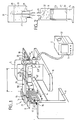
- FIG. 1 shows a scintillation device according to the invention.
- This mainly comprises a gamma camera 1 provided with its scintillator not shown, a network 21 of photomultiplier tubes of its detector D and a set of processing 2 and display 3 of emission images acquired by the gamma camera 1.
- the gamma camera detector is capable of rotating around the body of a patient (not shown) placed on a patient support panel 4.
- the gamma camera detector for this purpose is held by a frame 5 by a structure 8 in the form of a gallows.
- the structure 8 can rotate, in the direction of the arrow 6 around a horizontal axis 7. This allows the gamma camera detector 1 to rotate in a vertical plane around the horizontal axis 7.
- the bracket 8 is fixed on the one hand to the detector of the gamma camera 1 and on the other hand can rotate, driven by a motor not shown, around axis 7.
- the panel 4 and the frame 5 are held by bases respectively 9 and 10 one opposite the other.
- the bases can be movable relative to each other to move the body in front of the detector.
- the scintillation device of the invention also comprises a radioactive source 11 considered to be punctual and located inside a protective enclosure 12.
- the protective enclosure 12 is intended to protect the handlers from radioactive radiation emitted throughout the space by the source 11.
- the enclosure 12, for example made of lead, is therefore provided on one side facing the detector of the gamma camera 1 with an orifice through which the rays emitted by the source 11 can propagate.
- the source 11 is shown in FIG. 2.
- the enclosure 12 may comprise, on the side opposite to its orifice, a closable opening which allows the introduction of the radioactive source inside.
- the enclosure 12 is held integral with the gamma camera 1 by a potent arm 13.
- the arm 13 is fixed to the detector D by engagement in a set of slides 14 and 15 fixed to this detector.
- the arm 13 then rises substantially perpendicular to the plane of the detector D.
- the arm 13 is telescopic and has a forearm 16 which can penetrate inside the base 50 of the arm 13.
- the forearm 16 is finished in extension by a pivot 51 on which is mounted, free in rotation, perpendicular to the axis of the pivot, a telescopic arrow 52.
- the arrow 52 at its end opposite to the pivot, carries a crown 53 intended to receive the enclosure 12 inside sliding.
- the telescopic nature of the arm 13 and the arrow 52, as well as the rotation around the pivot 51 and the sliding of the enclosure 12 make it possible to give the source any position chosen in space relative to the detector D.
- the detector D is surmounted by a frame 17.
- the frame 17 also has fixing devices, for example by screws 19, which occupy exactly the same places and which overlap in exactly the same way as the fixing devices 20 of the collimator 18 on the gamma camera 1.
- the frame 17 is placed on the periphery of the network 21 of the photomultiplier tubes of the gamma camera detector 1.
- These photomultiplier tubes are shown, here symbolically, because in fact they are not visible (they are masked by the presence of the scintillator always necessary ).
- the network of these tubes can be round, hexagonal or even rectangular.
- the tubes themselves can have a round, hexagonal or square section.
- the frame 17 therefore has a hollowed out internal part capable of letting gamma radiation pass.
- the latter may be provided inside, with a plate, of transparent plastic.
- FIG. 2 shows a syringe 22, for example made of glass or plastic.
- the latter comprises a body 23 and a piston 24.
- the body 23 is provided with an orifice 25.
- the orifice 25 comprises a projection provided with a thread 26.
- the projection 25 can thus be screwed in the corresponding part of a hollow rod 27 which plunges into a jar 28.
- the jar 28 is preferably made of lead. It can be opaque.
- the rod 27 is held in the jar 28 by a stopper 29.
- the jar contains a dilution of radioactive product: preferably the same as that which is injectable into the patient. Given the capillarity of the liquids to be transported from the jar in the syringe 22, the diameters of the rod 27 and the orifice 25 are such that they naturally oppose the flow of the fluid 30 contained in the bottle 28.
- the filling mode is as follows.
- the bottle is normally placed on its bottom 31, the syringe 22 is screwed onto the rod 27, and the piston 24 is raised so that the syringe is filled.
- the syringe jar 28 assembly 22 is then turned over so that the jar is now placed above the syringe. In doing so, air bubbles 32 which would remain in the syringe 22 are placed near the orifice 25: they are expelled first as soon as the piston is pushed back.
- the piston 24 is then pushed back until it occupies a predetermined position 33 relative to the body 23.
- the quantity of fluid 30 in the syringe is always the same and, on the other hand, that the air bubbles have disappeared. Then the activity of the source is measured in an activimeter and the volume of liquid in the syringe is adjusted, repeating the same operations, so as to obtain the desired activity.
- the patient is stationary on the panel 4 and the gamma camera 1 rotates around him. Consequently, the source 11 takes vertical positions either above or below the patient. If we were not careful, the position of the bubbles such as 32 would distort the position of the center of gravity of the radioactive liquid contained in the syringe and therefore the position of the emission focal point.
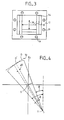
- FIG. 3 shows a frame 17 provided with its anchoring devices 19 and with a shutter diaphragm 34.
- This diaphragm here has two sets 35 and 36 of shutters making it possible to reduce the field of the gamma camera seen by the source 11. This makes it possible to avoid that regions of the detector of the camera, which would not be located in the projected image on it of the body to be studied, are not saturated by too much energy coming directly from the source 11. For example if we place the patient's head in front of the gamma camera, this will not mask the entire field of the gamma camera. Unmasked parts would otherwise receive direct radiation.
- the diaphragm is not symmetrically displaced.
- the flaps in at least one direction, for example direction 36 ( Figures 1 and 3), are provided to leave an opening at the edge of the plane of the detector rather than at its center.
- lateral parts not hatched and distant from the frame 5 of the detector D, are for example active in detection. Consequently, the support 4 can be moved in the direction of the arrow 60 so that only the patient's head is placed under the detector D of the gamma camera. The rest of the detector is then cantilevered relative to the head.
- the bracket of the structure 8, which is telescopic can be retracted into its leg 61 so that the detector passes as close as possible to the patient's head, in practice a few centimeters from the nose thereof.
- the detector is then closer to the head than if it had to go around the patient's belly, a belly which is naturally larger.
- the plate 4 is also narrower, at 62, where the patient must lay his head than where his trunk responds. This leads to better resolution since the detector can be placed closer to this patient's body.
- the detection range of the processing means 2 is reduced to less than 10% of the nominal value of the energy to be detected approximately to 5%. It will be recalled that in conventional emission detection, the range is of the order of 20% of the nominal value of the energy.
- FIG. 4 shows in section the detector D, of center D ′, located at a distance SD from the source 11.
- the detector is seen from the source 11 at a constant angle e.
- the rays which reach the detector on its right lateral edge 70 form, for a given acquisition direction, an angle ⁇ with an axis OY of a frame OXOY.
- the OXOY mark passes through the center of rotation of the gamma camera.
- the center of rotation is placed on the axis 7.
- the angle ⁇ characterizes the direction of projection.
- the projection of a sampled sector ⁇ on the detector D occupies on this detector a surface which depends on the deviation, with respect to an average direction SO of irradiation, from the detection position.
- the measurement made by weighting at each location of the detector is corrected by a coefficient which takes account of the attenuation caused by this surface occupation.
- a2 SD. (tg 2 ⁇ ⁇ tg ⁇ ).
- at i SD. (Tg i ⁇ - tg (i-1) ⁇ ).
- the measured values are corrected as a function of these coefficients.
- the weighting correction can be carried out by taking account of the deviation from the mean direction measured in one direction (35) and also in the other (36). With the difference measured in only one direction, the correction is already sufficient to remove a "bowl" effect in the reconstruction of the transmission attenuation coefficients.
- the gamma camera of the invention we are able to take around sixty views in a minute on a U-turn. These sixty views make it possible to determine the absorption coefficient of gamma radiation inside the body in volume elements whose dimension is of the order of 5 millimeters per side. Once these absorption coefficients have been acquired, we correct, using known techniques, tomography images obtained by emission and in which it was considered that the transmission attenuation was zero. Such a correction method was for example described in the first article cited above.
Landscapes
- Health & Medical Sciences (AREA)
- Physics & Mathematics (AREA)
- Life Sciences & Earth Sciences (AREA)
- Medical Informatics (AREA)
- Engineering & Computer Science (AREA)
- High Energy & Nuclear Physics (AREA)
- Molecular Biology (AREA)
- Nuclear Medicine, Radiotherapy & Molecular Imaging (AREA)
- Optics & Photonics (AREA)
- Biomedical Technology (AREA)
- General Health & Medical Sciences (AREA)
- Spectroscopy & Molecular Physics (AREA)
- General Physics & Mathematics (AREA)
- Radiology & Medical Imaging (AREA)
- Surgery (AREA)
- Animal Behavior & Ethology (AREA)
- Heart & Thoracic Surgery (AREA)
- Public Health (AREA)
- Veterinary Medicine (AREA)
- Pathology (AREA)
- Biophysics (AREA)
- Nuclear Medicine (AREA)
- Apparatus For Radiation Diagnosis (AREA)
Claims (8)
- Szintillationsvorrichtung mit einer Gamma-Kamera (1) zur Messung der Transmissionsabschwächung , quer durch einen zu untersuchenden Körper, einer Gammastrahlung, die von einer radioaktiven Punktquelle (11) abgegeben wird, die gegenüber einem Detektor (D) der Gamma-Kamera gehalten wird, wobei der Detektor von einem Kollimator (18) befreit und auf einer ersten Seite des Körpers gegenüber einer weiteren Seite des Körpers angeordnet ist, auf der die Punktquelle angeordnet ist, und wobei die durch die Punktquelle und den Detektor gebildete Einheit gegenüber dem Körper drehbar ist, dadurch gekennzeichnet, daß die Gamma-Kamera an einem beweglichen Aufbau (8) montiert ist, durch den die Gamma-Kamera in einer Vertikalebene um den Körper drehbar ist, der horizontal ausgestreckt auf einem Träger (4) liegt, daß dieser Aufbau auch die Gammastrahlungs-Punktquelle mitbewegt, und daß Mittel vorgesehen sind, um die gemessene Abschwächung in Abhängigkeit von dem Abstand Quelle-Detektor und in Abhängigkeit von der Planheit des Detektors zu gewichten.
- Vorrichtung nach Anspruch 1, dadurch gekennzeichnet, daß der Detektor der Gamma-Kamera mit einem beweglichen Rahmen versehen ist, der an dem Außenumfang des Detektors angeordnet ist.
- Vorrichtung nach Anspruch 2, dadurch gekennzeichnet, daß der Rahmen eine Blende (34) enthält, um das von der Punktquelle gesehene Feld der Gamma-Kamera zu verringern.
- Vorrichtung nach Anspruch 2 oder 3, dadurch gekennzeichnet, daß der Rahmen ein Gewicht besitzt, das im wesentlichen gleich dem Gewicht des fehlenden Kollimators ist.
- Vorrichtung nach Anspruch 3, dadurch gekennzeichnet, daß die Blende Verschlußklappen mit unsymmetrischer Verstellung aufweist.
- Vorrichtung nach einem der Ansprüche 1 bis 5, dadurch gekennzeichnet, daß die Punktquelle in einer Spritze enthalten ist.
- Vorrichtung nach Anspruch 6, dadurch gekennzeichnet, daß sie einen Glasbehälter enthält, der mit einer Hohlstange (27) versehen ist, die mit einem Ende in das Innere des Glasbehälters eintaucht und an ihrem anderen Ende einen Sammelbereich zur Aufnahme einer Öffnung (25) der Spritze aufweist.
- Vorrichtung nach einem der Ansprüche 1 bis 7, dadurch gekennzeichnet, daß sie unter den Mitteln (2) zur Verarbeitung des erfaßten Signals Mittel (37) enthält, um den erfaßten Energiebereich auf weniger als 10% des Nennwertes der zu erfassenden Energie der Gamma-Photonen zu verringern.
Priority Applications (1)
| Application Number | Priority Date | Filing Date | Title |
|---|---|---|---|
| AT90912241T ATE98026T1 (de) | 1989-07-28 | 1990-07-24 | Szintillationsvorrichtung zur messung der signalabschwaechung mit hilfe von transmissionstomographie. |
Applications Claiming Priority (2)
| Application Number | Priority Date | Filing Date | Title |
|---|---|---|---|
| FR8910225A FR2650397B1 (fr) | 1989-07-28 | 1989-07-28 | Dispositif a scintillation utilisable pour mesurer l'attenuation par tomographie de transmission |
| FR8910225 | 1989-07-28 |
Publications (2)
| Publication Number | Publication Date |
|---|---|
| EP0484430A1 EP0484430A1 (de) | 1992-05-13 |
| EP0484430B1 true EP0484430B1 (de) | 1993-12-01 |
Family
ID=9384266
Family Applications (1)
| Application Number | Title | Priority Date | Filing Date |
|---|---|---|---|
| EP90912241A Expired - Lifetime EP0484430B1 (de) | 1989-07-28 | 1990-07-24 | Szintillationsvorrichtung zur messung der signalabschwächung mit hilfe von transmissionstomographie |
Country Status (9)
| Country | Link |
|---|---|
| US (1) | US5359198A (de) |
| EP (1) | EP0484430B1 (de) |
| JP (1) | JP2919963B2 (de) |
| CA (1) | CA2064033C (de) |
| DE (1) | DE69004963T2 (de) |
| ES (1) | ES2050449T3 (de) |
| FR (1) | FR2650397B1 (de) |
| IL (1) | IL95204A0 (de) |
| WO (1) | WO1991002265A1 (de) |
Families Citing this family (7)
| Publication number | Priority date | Publication date | Assignee | Title |
|---|---|---|---|---|
| FR2721411B1 (fr) * | 1994-06-15 | 1996-08-23 | Sopha Medical | Procédé d'acquisition en médecine nucléaire d'une image en transmission. |
| FR2733841B1 (fr) * | 1995-05-04 | 1997-05-30 | Commissariat Energie Atomique | Procede de realisation de la cartographie d'emission d'un corps corrigee de l'attenuation par ce corps |
| US6718006B2 (en) * | 1998-05-01 | 2004-04-06 | Cti Pet Systems, Inc. | Fiber-optic encoding for dual transmission measurements in positron emission tomography |
| AU2003281907A1 (en) * | 2003-11-20 | 2005-06-08 | Ge Medical Systems Global Technology Company, Llc. | Collimator and radiation irradiator |
| JP2015501435A (ja) | 2011-11-02 | 2015-01-15 | ジョンソン、マッセイ、パブリック、リミテッド、カンパニーJohnson Matthey Publiclimited Company | スキャン方法及び装置 |
| GB201604246D0 (en) * | 2016-03-11 | 2016-04-27 | Univ Hull | Radioactivity detection |
| CN116819601B (zh) * | 2023-06-29 | 2026-03-20 | 西北核技术研究所 | 一种宽能伽马射线标准面源及其制备方法 |
Family Cites Families (22)
| Publication number | Priority date | Publication date | Assignee | Title |
|---|---|---|---|---|
| AU505730B2 (en) * | 1976-05-07 | 1979-11-29 | Ohio-Nuclear, Inc | Correction circuit for scintillation camera |
| IT1083835B (it) * | 1977-06-15 | 1985-05-25 | Selo | Apparechiatura per tomografia a gamma camera |
| US4212061A (en) * | 1977-12-21 | 1980-07-08 | Medtronic, Inc. | Radiation signal processing system |
| US4223221A (en) * | 1978-06-19 | 1980-09-16 | Picker Corporation | Scintillation camera uniformity correction |
| US4216381A (en) * | 1979-05-10 | 1980-08-05 | General Electric Company | Structure for emission tomography scintillation camera |
| US4323977A (en) * | 1979-11-20 | 1982-04-06 | Siemens Gammasonics, Inc. | Non-uniformity energy correction method and apparatus |
| US4429226A (en) * | 1980-05-13 | 1984-01-31 | Elscint, Inc. | Method of and means for improving the resolution of a gamma camera |
| US4424446B1 (en) * | 1980-06-19 | 1994-04-19 | Elscint Ltd | Gamma camera correction system and method for using the same |
| JPS5892974A (ja) * | 1981-11-30 | 1983-06-02 | Shimadzu Corp | 放射型コンピユ−タ断層撮影装置 |
| US4503331A (en) * | 1982-04-21 | 1985-03-05 | Technicare Corporation | Non-circular emission computed tomography |
| DE3236082A1 (de) * | 1982-09-29 | 1984-03-29 | Siemens AG, 1000 Berlin und 8000 München | Strahlenblende fuer ein roentgenuntersuchungsgeraet |
| JPS59180477A (ja) * | 1983-03-31 | 1984-10-13 | Shimadzu Corp | シングルフォトンエミッションct装置 |
| US4780823A (en) * | 1986-03-11 | 1988-10-25 | Siemens Gammasonics, Inc. | Multiple pixel area-weighted acquisition system for scintillation cameras |
| US4788429A (en) * | 1986-04-21 | 1988-11-29 | The Medical College Of Wisconsin, Inc. | Device and method for measuring bone mineral mass |
| GB2197570A (en) * | 1986-11-07 | 1988-05-18 | Philips Nv | Gamma tomography apparatus |
| JP2606232B2 (ja) * | 1987-09-28 | 1997-04-30 | 松下電器産業株式会社 | 交通信号制御装置 |
| JPH0619439B2 (ja) * | 1989-08-04 | 1994-03-16 | 株式会社東芝 | Spect装置 |
| FR2653897B1 (fr) * | 1989-11-02 | 1994-07-29 | Informatek Sopha Medical Ste N | Equipement gamma camera a deux tetes detectrices. |
| US5047641A (en) * | 1990-03-14 | 1991-09-10 | Siemens Gammasonics, Inc. | Scintillation camera with automatically counterbalanced gantry |
| US5172695A (en) * | 1990-09-10 | 1992-12-22 | Cann Christopher E | Method for improved prediction of bone fracture risk using bone mineral density in structural analysis |
| US5228068A (en) * | 1992-09-14 | 1993-07-13 | Lunar Corporation | Device and method for automated determination and analysis of bone density and vertebral morphology |
| US5185529A (en) * | 1991-06-07 | 1993-02-09 | Digital Scintigraphics, Inc. | Position analysis system and method |
-
1989
- 1989-07-28 FR FR8910225A patent/FR2650397B1/fr not_active Expired - Fee Related
-
1990
- 1990-07-24 EP EP90912241A patent/EP0484430B1/de not_active Expired - Lifetime
- 1990-07-24 WO PCT/FR1990/000560 patent/WO1991002265A1/fr not_active Ceased
- 1990-07-24 ES ES90912241T patent/ES2050449T3/es not_active Expired - Lifetime
- 1990-07-24 JP JP2511469A patent/JP2919963B2/ja not_active Expired - Lifetime
- 1990-07-24 CA CA002064033A patent/CA2064033C/fr not_active Expired - Fee Related
- 1990-07-24 DE DE90912241T patent/DE69004963T2/de not_active Expired - Fee Related
- 1990-07-27 IL IL95204A patent/IL95204A0/xx not_active IP Right Cessation
-
1992
- 1992-03-27 US US07/820,613 patent/US5359198A/en not_active Expired - Fee Related
Also Published As
| Publication number | Publication date |
|---|---|
| WO1991002265A1 (fr) | 1991-02-21 |
| JP2919963B2 (ja) | 1999-07-19 |
| JPH05503145A (ja) | 1993-05-27 |
| FR2650397A1 (fr) | 1991-02-01 |
| ES2050449T3 (es) | 1994-05-16 |
| DE69004963T2 (de) | 1994-03-24 |
| DE69004963D1 (de) | 1994-01-13 |
| IL95204A0 (en) | 1991-06-10 |
| CA2064033C (fr) | 2000-03-07 |
| FR2650397B1 (fr) | 1991-10-04 |
| EP0484430A1 (de) | 1992-05-13 |
| US5359198A (en) | 1994-10-25 |
| CA2064033A1 (fr) | 1991-01-29 |
Similar Documents
| Publication | Publication Date | Title |
|---|---|---|
| JP6200428B2 (ja) | X線検出器、x線装置、プロセッサ、コンピュータプログラム、及びその関連方法 | |
| US20110073763A1 (en) | Method and apparatus for high-sensitivity Single-Photon Emission Computed Tomography | |
| JP5920930B2 (ja) | ガンマカメラ、spect装置、pet装置およびガンマ線計測画像生成方法 | |
| EP0484430B1 (de) | Szintillationsvorrichtung zur messung der signalabschwächung mit hilfe von transmissionstomographie | |
| EP1188070B1 (de) | Vorrichtung zum nachweis und zum orten einer radioaktiven, gammastrahlung aussendenden quelle und deren verwendung | |
| CA3053944A1 (fr) | Procede de mesure et de representation du niveau des doses locales d'irradiation | |
| Gottschalk et al. | SPECT resolution and uniformity improvements by noncircular orbit | |
| JP2001324570A (ja) | 透過放射線補正型ガンマ線カメラ及びそれを用いた診断画像形成方法 | |
| Koral et al. | Improving emission-computed-tomography quantification by Compton-scatter rejection through offset windows | |
| EP0253742B1 (de) | Gerät zur Bestimmung des Kalziumgehaltes von Knochen | |
| EP0782009B1 (de) | Verfahren zur Erzeugung eines Übertragungsbildes in Nuklearmedizin | |
| JPH0763464B2 (ja) | X線ct装置 | |
| EP4010739B1 (de) | Rotierender kollimator für ein röntgendetektionssystem | |
| FR2805730A1 (fr) | Procede et systeme de positionnement automatique d'un appareil de radiologie, programme associe et appareil de radiologie | |
| Tenney et al. | Uranium pinhole collimators for 511-keV photon SPECT imaging of small volumes | |
| JPH0684988B2 (ja) | ベツド吸収補正装置 | |
| EP3987312A1 (de) | Compton-kamera und verfahren zur 3d-abbildung | |
| Daba | Quality Assurance of Intra-oral X-ray Images | |
| Vaiano | Standard Operating Procedures for Quality Control of Gamma Cameras | |
| JPS5979879A (ja) | エミツシヨン型コンピユ−タ断層撮影装置 | |
| Grošev et al. | Extension of the International Atomic Energy Agency phantom study in image quantification: results of multicentre evaluation in Croatia | |
| JPH0332759B2 (de) | ||
| Li et al. | Lesion quantification in dual-modality mammotomography | |
| Goodwin et al. | Methods for comparing the performance of different gamma cameras | |
| JP2005249412A (ja) | 放射能画像化装置 |
Legal Events
| Date | Code | Title | Description |
|---|---|---|---|
| PUAI | Public reference made under article 153(3) epc to a published international application that has entered the european phase |
Free format text: ORIGINAL CODE: 0009012 |
|
| 17P | Request for examination filed |
Effective date: 19920117 |
|
| AK | Designated contracting states |
Kind code of ref document: A1 Designated state(s): AT DE ES FR GB IT NL |
|
| 17Q | First examination report despatched |
Effective date: 19930408 |
|
| GRAA | (expected) grant |
Free format text: ORIGINAL CODE: 0009210 |
|
| ITF | It: translation for a ep patent filed | ||
| AK | Designated contracting states |
Kind code of ref document: B1 Designated state(s): AT DE ES FR GB IT NL |
|
| REF | Corresponds to: |
Ref document number: 98026 Country of ref document: AT Date of ref document: 19931215 Kind code of ref document: T |
|
| GBT | Gb: translation of ep patent filed (gb section 77(6)(a)/1977) |
Effective date: 19931209 |
|
| REF | Corresponds to: |
Ref document number: 69004963 Country of ref document: DE Date of ref document: 19940113 |
|
| REG | Reference to a national code |
Ref country code: ES Ref legal event code: FG2A Ref document number: 2050449 Country of ref document: ES Kind code of ref document: T3 |
|
| PLBE | No opposition filed within time limit |
Free format text: ORIGINAL CODE: 0009261 |
|
| STAA | Information on the status of an ep patent application or granted ep patent |
Free format text: STATUS: NO OPPOSITION FILED WITHIN TIME LIMIT |
|
| 26N | No opposition filed | ||
| REG | Reference to a national code |
Ref country code: FR Ref legal event code: GC |
|
| PGFP | Annual fee paid to national office [announced via postgrant information from national office to epo] |
Ref country code: AT Payment date: 20000627 Year of fee payment: 11 |
|
| PGFP | Annual fee paid to national office [announced via postgrant information from national office to epo] |
Ref country code: NL Payment date: 20000629 Year of fee payment: 11 Ref country code: GB Payment date: 20000629 Year of fee payment: 11 |
|
| PGFP | Annual fee paid to national office [announced via postgrant information from national office to epo] |
Ref country code: DE Payment date: 20000705 Year of fee payment: 11 |
|
| PGFP | Annual fee paid to national office [announced via postgrant information from national office to epo] |
Ref country code: ES Payment date: 20000717 Year of fee payment: 11 |
|
| PGFP | Annual fee paid to national office [announced via postgrant information from national office to epo] |
Ref country code: FR Payment date: 20000726 Year of fee payment: 11 |
|
| PG25 | Lapsed in a contracting state [announced via postgrant information from national office to epo] |
Ref country code: GB Free format text: LAPSE BECAUSE OF NON-PAYMENT OF DUE FEES Effective date: 20010724 Ref country code: AT Free format text: LAPSE BECAUSE OF NON-PAYMENT OF DUE FEES Effective date: 20010724 |
|
| PG25 | Lapsed in a contracting state [announced via postgrant information from national office to epo] |
Ref country code: ES Free format text: LAPSE BECAUSE OF NON-PAYMENT OF DUE FEES Effective date: 20010725 |
|
| PG25 | Lapsed in a contracting state [announced via postgrant information from national office to epo] |
Ref country code: NL Free format text: LAPSE BECAUSE OF NON-PAYMENT OF DUE FEES Effective date: 20020201 |
|
| GBPC | Gb: european patent ceased through non-payment of renewal fee |
Effective date: 20010724 |
|
| PG25 | Lapsed in a contracting state [announced via postgrant information from national office to epo] |
Ref country code: FR Free format text: LAPSE BECAUSE OF NON-PAYMENT OF DUE FEES Effective date: 20020329 |
|
| NLV4 | Nl: lapsed or anulled due to non-payment of the annual fee |
Effective date: 20020201 |
|
| PG25 | Lapsed in a contracting state [announced via postgrant information from national office to epo] |
Ref country code: DE Free format text: LAPSE BECAUSE OF NON-PAYMENT OF DUE FEES Effective date: 20020501 |
|
| REG | Reference to a national code |
Ref country code: FR Ref legal event code: ST |
|
| REG | Reference to a national code |
Ref country code: ES Ref legal event code: FD2A Effective date: 20020810 |
|
| PG25 | Lapsed in a contracting state [announced via postgrant information from national office to epo] |
Ref country code: IT Free format text: LAPSE BECAUSE OF NON-PAYMENT OF DUE FEES Effective date: 20050724 |