EP0484305B1 - High speed whirlpool pump - Google Patents
High speed whirlpool pump Download PDFInfo
- Publication number
- EP0484305B1 EP0484305B1 EP91850247A EP91850247A EP0484305B1 EP 0484305 B1 EP0484305 B1 EP 0484305B1 EP 91850247 A EP91850247 A EP 91850247A EP 91850247 A EP91850247 A EP 91850247A EP 0484305 B1 EP0484305 B1 EP 0484305B1
- Authority
- EP
- European Patent Office
- Prior art keywords
- motor
- fan
- vanes
- speed
- pump
- Prior art date
- Legal status (The legal status is an assumption and is not a legal conclusion. Google has not performed a legal analysis and makes no representation as to the accuracy of the status listed.)
- Expired - Lifetime
Links
Images
Classifications
-
- F—MECHANICAL ENGINEERING; LIGHTING; HEATING; WEAPONS; BLASTING
- F04—POSITIVE - DISPLACEMENT MACHINES FOR LIQUIDS; PUMPS FOR LIQUIDS OR ELASTIC FLUIDS
- F04D—NON-POSITIVE-DISPLACEMENT PUMPS
- F04D25/00—Pumping installations or systems
- F04D25/02—Units comprising pumps and their driving means
- F04D25/06—Units comprising pumps and their driving means the pump being electrically driven
-
- H—ELECTRICITY
- H02—GENERATION; CONVERSION OR DISTRIBUTION OF ELECTRIC POWER
- H02K—DYNAMO-ELECTRIC MACHINES
- H02K23/00—DC commutator motors or generators having mechanical commutator; Universal AC/DC commutator motors
- H02K23/66—Structural association with auxiliary electric devices influencing the characteristic of, or controlling, the machine, e.g. with impedances or switches
-
- A—HUMAN NECESSITIES
- A61—MEDICAL OR VETERINARY SCIENCE; HYGIENE
- A61H—PHYSICAL THERAPY APPARATUS, e.g. DEVICES FOR LOCATING OR STIMULATING REFLEX POINTS IN THE BODY; ARTIFICIAL RESPIRATION; MASSAGE; BATHING DEVICES FOR SPECIAL THERAPEUTIC OR HYGIENIC PURPOSES OR SPECIFIC PARTS OF THE BODY
- A61H33/00—Bathing devices for special therapeutic or hygienic purposes
- A61H33/60—Components specifically designed for the therapeutic baths of groups A61H33/00
-
- F—MECHANICAL ENGINEERING; LIGHTING; HEATING; WEAPONS; BLASTING
- F04—POSITIVE - DISPLACEMENT MACHINES FOR LIQUIDS; PUMPS FOR LIQUIDS OR ELASTIC FLUIDS
- F04D—NON-POSITIVE-DISPLACEMENT PUMPS
- F04D13/00—Pumping installations or systems
- F04D13/02—Units comprising pumps and their driving means
- F04D13/06—Units comprising pumps and their driving means the pump being electrically driven
-
- F—MECHANICAL ENGINEERING; LIGHTING; HEATING; WEAPONS; BLASTING
- F04—POSITIVE - DISPLACEMENT MACHINES FOR LIQUIDS; PUMPS FOR LIQUIDS OR ELASTIC FLUIDS
- F04D—NON-POSITIVE-DISPLACEMENT PUMPS
- F04D29/00—Details, component parts, or accessories
- F04D29/08—Sealings
- F04D29/10—Shaft sealings
- F04D29/12—Shaft sealings using sealing-rings
- F04D29/126—Shaft sealings using sealing-rings especially adapted for liquid pumps
-
- F—MECHANICAL ENGINEERING; LIGHTING; HEATING; WEAPONS; BLASTING
- F04—POSITIVE - DISPLACEMENT MACHINES FOR LIQUIDS; PUMPS FOR LIQUIDS OR ELASTIC FLUIDS
- F04D—NON-POSITIVE-DISPLACEMENT PUMPS
- F04D29/00—Details, component parts, or accessories
- F04D29/08—Sealings
- F04D29/16—Sealings between pressure and suction sides
- F04D29/165—Sealings between pressure and suction sides especially adapted for liquid pumps
- F04D29/167—Sealings between pressure and suction sides especially adapted for liquid pumps of a centrifugal flow wheel
-
- F—MECHANICAL ENGINEERING; LIGHTING; HEATING; WEAPONS; BLASTING
- F04—POSITIVE - DISPLACEMENT MACHINES FOR LIQUIDS; PUMPS FOR LIQUIDS OR ELASTIC FLUIDS
- F04D—NON-POSITIVE-DISPLACEMENT PUMPS
- F04D29/00—Details, component parts, or accessories
- F04D29/18—Rotors
- F04D29/22—Rotors specially for centrifugal pumps
- F04D29/2261—Rotors specially for centrifugal pumps with special measures
- F04D29/2277—Rotors specially for centrifugal pumps with special measures for increasing NPSH or dealing with liquids near boiling-point
-
- F—MECHANICAL ENGINEERING; LIGHTING; HEATING; WEAPONS; BLASTING
- F04—POSITIVE - DISPLACEMENT MACHINES FOR LIQUIDS; PUMPS FOR LIQUIDS OR ELASTIC FLUIDS
- F04D—NON-POSITIVE-DISPLACEMENT PUMPS
- F04D29/00—Details, component parts, or accessories
- F04D29/26—Rotors specially for elastic fluids
- F04D29/28—Rotors specially for elastic fluids for centrifugal or helico-centrifugal pumps for radial-flow or helico-centrifugal pumps
- F04D29/281—Rotors specially for elastic fluids for centrifugal or helico-centrifugal pumps for radial-flow or helico-centrifugal pumps for fans or blowers
-
- F—MECHANICAL ENGINEERING; LIGHTING; HEATING; WEAPONS; BLASTING
- F04—POSITIVE - DISPLACEMENT MACHINES FOR LIQUIDS; PUMPS FOR LIQUIDS OR ELASTIC FLUIDS
- F04D—NON-POSITIVE-DISPLACEMENT PUMPS
- F04D29/00—Details, component parts, or accessories
- F04D29/40—Casings; Connections of working fluid
- F04D29/42—Casings; Connections of working fluid for radial or helico-centrifugal pumps
- F04D29/4206—Casings; Connections of working fluid for radial or helico-centrifugal pumps especially adapted for elastic fluid pumps
- F04D29/422—Discharge tongues
-
- F—MECHANICAL ENGINEERING; LIGHTING; HEATING; WEAPONS; BLASTING
- F04—POSITIVE - DISPLACEMENT MACHINES FOR LIQUIDS; PUMPS FOR LIQUIDS OR ELASTIC FLUIDS
- F04D—NON-POSITIVE-DISPLACEMENT PUMPS
- F04D29/00—Details, component parts, or accessories
- F04D29/40—Casings; Connections of working fluid
- F04D29/42—Casings; Connections of working fluid for radial or helico-centrifugal pumps
- F04D29/426—Casings; Connections of working fluid for radial or helico-centrifugal pumps especially adapted for liquid pumps
- F04D29/4273—Casings; Connections of working fluid for radial or helico-centrifugal pumps especially adapted for liquid pumps suction eyes
-
- H—ELECTRICITY
- H02—GENERATION; CONVERSION OR DISTRIBUTION OF ELECTRIC POWER
- H02K—DYNAMO-ELECTRIC MACHINES
- H02K5/00—Casings; Enclosures; Supports
- H02K5/04—Casings or enclosures characterised by the shape, form or construction thereof
- H02K5/08—Insulating casings
-
- A—HUMAN NECESSITIES
- A61—MEDICAL OR VETERINARY SCIENCE; HYGIENE
- A61H—PHYSICAL THERAPY APPARATUS, e.g. DEVICES FOR LOCATING OR STIMULATING REFLEX POINTS IN THE BODY; ARTIFICIAL RESPIRATION; MASSAGE; BATHING DEVICES FOR SPECIAL THERAPEUTIC OR HYGIENIC PURPOSES OR SPECIFIC PARTS OF THE BODY
- A61H33/00—Bathing devices for special therapeutic or hygienic purposes
Definitions
- This invention relates to an electric machine according to the preamble of claim 1 and more particularly to such a machine including a high speed pump for Whirlpool and Spa applications.
- Whirlpool pumps provide flow and pressure to the liquid to be circulated in the normal manner consistent with single stage centrifugal, Kinetic pumps, of radial vane, closed impeller construction. Substantially all of the whirlpool pumps are driven by various types of induction motors, as is the case with most electric motor driven centrifugal pumps.
- the biggest shortcoming with the above mentioned current devices is the inherent relative high cost of the motor.
- the size and, therefore, cost of the motor is inversely related to the motor speed. The higher the speed the smaller the size and the lower the cost.
- the maximum motor speed on normal household A. C. current is 3600 RPM, based on an A.C. induction motor, with the minimum number (two) of motor poles and 60 cycles per second current frequency in the USA.
- Devices have been developed for induction type A.C. motors which can vary the cycle frequency (and therefore motor speed) up or down, however, this does not reduce, but rather increase the complexity and cost of the motor plus controls package.
- FR-A-2565296 discloses a high speed pump for sanitary equipment provided with a turbine type impeller, the speed of which however, is restricted by insufficient cooling means.
- An object of the invention is to provide an electric machine including a motor and an improved pump which operates at high speed. This object is achieved by a machine having the features of claim 1.
- a series wound universal motor is used to power, thru a direct drive (close coupled), a high speed centrifugal impeller, to speeds in the range of 4000 RPM to 9000 RPM, for whirlpool and Spa applications.
- a universal motor is cheaper than a single speed, two speed or variable speed induction motor, due to the higher speed and subsequent smaller motor size.
- variable speed is easily accomplished with a universal motor by just varying only the voltage to the motor, and variable speed is a desirable option in the Whirlpool and Spa market.
- a feature of the invention includes unique modifications to the pump motor fan to both reduce the motor noise level and increase motor cooling.
- the basic function of a motor cooling fan is to draw ambient air into the motor housing, thru the stator laminations, over the field coils, armature, commutator and brushes, while providing sufficient air currents to also cool the motor bearings.
- Fans of this are well known to the motor industry, and for best cooling and noise they normally maximize the number of vanes on the fan to the point that additional full vanes will block air flow through the inlet portion of the fan.
- the fan according to the invention is more effective (quieter and better cooling) due to the application of splitter (short) vanes equally spaced between the normal full length fan blades, coupled with a reduction of the rear fan shroud diameter below the maximum blade outer diameter.
- splitter vanes allows more blades/vanes to be used on the fan without blocking the air inlet to the fan.
- the higher number of blades/vanes reduces the pressure loading on the fan individual blades/vanes, which reduces the noise level, and increases the frequency of the motor noise which makes the noise easier to block.
- the reduction of the rear shroud reduces the blockage of the axial component of the air flow at the discharge of the fan, as it exits the motor housing vents with as little restriction as possible.
- the better cooling from this fan also allows a smaller outer fan diameter which further reduces the noise level.
- the main feature of this invention includes a modification to the motor housing stationary "peeler" tongue which is close to the outer diameter of the fan blades and vanes.
- the peeler tongue has been skewed at an angle with respect to the fan blades to further reduce motor/fan noise. Without the skewing, the valving effect of the high and low pressure sides of each fan vane passing close to the peeler tongue causes strong pressure pulsations, or noise. By skewing the peeler tongue, this causes a more gradual fluctuation of the fan exit pressure as the fan blades pass close to the tongue, thus generating less noise.
- the apparatus includes a suction cover 11, suction inlet 12, insert 13, and self-draining channel 14.
- a O-ring 16 is positioned between cover 11 and casing 18 having an outlet 19.
- Cover 11 and casing 18 are mounted to universal motor housing 20 by self taping screws in a standard manner.
- the universal motor includes a stator 22 and an armature 24.
- the armature 24 includes a commutator 25, and a shaft 26 having a threaded end 27 and a splined end 28.
- the commutator brushes for the universal motor are located in the housing 20 in a plane perpendicular to the cross-sectional view.
- Inducerpeller 30 Threaded on shaft end 27 is an inducerpeller 30 having mounted thereon a rubber boot 31, ceramic ring 32, and metal retaining ring 33 which form part of a mechanical seal.
- the other part of the mechanical seal includes a carbon seal ring 35, rubber boot 36, spring 37, and retaining cup 38.
- An O-ring 39 is positioned between cup 38 and casing 18.
- Inducerpeller 30 has two step front surfaces 40, 41 which run with a clearance between the complementary inner surfaces 13a, 13b of insert 13 to provide an impeller seal wear ring surface to reduce recirculation leakage flow into the pump suction.
- the inducerpeller has a vane 42 with a vane portion 42a which extends forward along the axial portion of the front shroud 40a, and sweeps back an angle of approximately 5° to 15° to the impeller axis to improve suction performance.
- a slinger 44 is mounted on shaft 26 adjacent bearing hub 46 of housing 20.
- Bearings 48, rotatably mount shaft 26 in hub 46, and bearings 50 rotatably mount the splined end 28 to housing bearing surface 52, and bearing 50 is retained on housing bearing surface 52 by means of strap 53.
- a fan 55 is spline mounted on the spline end 28 of shaft 26.
- An elastomeric motor mounting foot 60 encloses a compartment 61, in which may be mounted a circuit board 62 for mounting electrical components 62a, b for motor speed control.
- Back plate 65 encloses another compartment 66 in which may be mounted another circuit board 67 for mounting other of the electrical components 67a, b to control motor speed.
- Terminals 70, 71, 72 are used to connect leads to and from circuit boards and power source.
- Power leads (not shown) are coupled through opening 21 in housing 20 in known manner.
- Eack plate 65 may be metal to facilitate heat transfer though fins 65a from circuit board 67 which may be the high power circuit board of the control requiring the most heat dissipation.
- cover 11, insert 13, casing 18, housing 20, inducerpeller 30, fan 55, and mounting foot 60 are made of plastic suitable for injection molding.
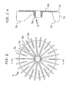
- FIGS 2 and 2A illustrate the motor fan according to the invention.
- the fan 55 includes thirteen full length blades 55a, thirteen short (splitter) vanes 55b, a hub 55c for pressing onto splined shaft, and a rear fan shroud 55d.
- the rear fan shroud 55d has a diameter 55e which is less than the diameter 55f.
- the splitter vanes equally spaced between the full length blades improves the effective cooling
- the reduced shroud diameter improves the air flow at the discharge of the fan as it exits the motor housing.
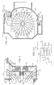
- FIG 3 is a partial cross-sectional view taken along lines 4-4 of figure 1 to show the effect of air flow through the fan and vents.
- Motor housing 20 has housing vents 20a, 20b for air exhaust from fan 55.
- Rear fan shroud 55d has a diameter 55e shorter than the outer diameter 55f to facilitate air flow represented by arrows 80, 81 to the exhaust vents throughout the fan compartment 20c.
- a peeler tongue 20d is shown in vent 20a close to the outer diameter of the fan blades/vanes, and as shown in Figure 3B, the motor housing 20 peeler tongue 20d is skewed at an angle 84 of approximately fifteen degrees with respect to the fan blades 55a to further reduce motor/fan noise. Without skewing, the high and low pressure sides of the blades/vanes cause higher pressure pulsations or increased noise.
Description
- This invention relates to an electric machine according to the preamble of claim 1 and more particularly to such a machine including a high speed pump for Whirlpool and Spa applications.
- An electric machine of this kind is known from FR-A-2565296.
- Other similar devices primarily fall into five categories:
- a. Close coupled end suction (non-self draining), low speed pump on single speed, A.C. induction motor.
- b. Close coupled end suction, self-draining, low speed pump on single speed, A.C. induction motor.
- c. Close coupled end suction (non-self draining), low speed pump on two speed, A.C. induction motor.
- d. Close coupled end suction, self-draining, low speed pump on variable speed, variable frequency induction motor.
- e. Belt driven, low speed submersible pump powered by high speed series wound universal motor (portable Whirlpool units only).
- All of the above categories of Whirlpool pumps, provide flow and pressure to the liquid to be circulated in the normal manner consistent with single stage centrifugal, Kinetic pumps, of radial vane, closed impeller construction. Substantially all of the whirlpool pumps are driven by various types of induction motors, as is the case with most electric motor driven centrifugal pumps.
- The biggest shortcoming with the above mentioned current devices is the inherent relative high cost of the motor. The size and, therefore, cost of the motor is inversely related to the motor speed. The higher the speed the smaller the size and the lower the cost. The maximum motor speed on normal household A. C. current is 3600 RPM, based on an A.C. induction motor, with the minimum number (two) of motor poles and 60 cycles per second current frequency in the USA. Devices have been developed for induction type A.C. motors which can vary the cycle frequency (and therefore motor speed) up or down, however, this does not reduce, but rather increase the complexity and cost of the motor plus controls package.
- Even when the motor speed (and therefore pump speed) is increased by means of a variable frequency device, there is a limit to the speed of a conventional centrifugal pump in whirlpool or Spa applications due to cavitation in the inlet of the impeller vanes. This is why belt-driven submersible pumps powered by high speed universal motors are stepped down to about 3600 RPM today. Further, conventional universal motors are inherently noisy and must normally operate at very high speeds (over 10,000 RPM) to provide sufficient cooling for the power levels required with a fixed installation Whirlpool pump.
- FR-A-2565296 discloses a high speed pump for sanitary equipment provided with a turbine type impeller, the speed of which however, is restricted by insufficient cooling means.
- Additionally, the following patents were developed in searching the various features of the invention:
US Patent No 353 994 4 661 041 3 384 022 4 019 829 4 449 889 4 523 900 4 642 023 4 213 742 4 389 159 4 518 311 3 516 757 4 126 360 4 286 919 2 991 927 4 842 481 3 286 639 French Patent No 2 389 784 - Accordingly, the high speed pump for Whirlpool and Spa application of the invention overcomes the limitations of the prior art devices.
- An object of the invention is to provide an electric machine including a motor and an improved pump which operates at high speed. This object is achieved by a machine having the features of claim 1.
- According to the broader aspects of this invention, a series wound universal motor is used to power, thru a direct drive (close coupled), a high speed centrifugal impeller, to speeds in the range of 4000 RPM to 9000 RPM, for whirlpool and Spa applications. A universal motor is cheaper than a single speed, two speed or variable speed induction motor, due to the higher speed and subsequent smaller motor size. Also, variable speed is easily accomplished with a universal motor by just varying only the voltage to the motor, and variable speed is a desirable option in the Whirlpool and Spa market.
- A feature of the invention includes unique modifications to the pump motor fan to both reduce the motor noise level and increase motor cooling. The basic function of a motor cooling fan is to draw ambient air into the motor housing, thru the stator laminations, over the field coils, armature, commutator and brushes, while providing sufficient air currents to also cool the motor bearings. Fans of this are well known to the motor industry, and for best cooling and noise they normally maximize the number of vanes on the fan to the point that additional full vanes will block air flow through the inlet portion of the fan. The fan according to the invention is more effective (quieter and better cooling) due to the application of splitter (short) vanes equally spaced between the normal full length fan blades, coupled with a reduction of the rear fan shroud diameter below the maximum blade outer diameter. The use of splitter vanes allows more blades/vanes to be used on the fan without blocking the air inlet to the fan. The higher number of blades/vanes reduces the pressure loading on the fan individual blades/vanes, which reduces the noise level, and increases the frequency of the motor noise which makes the noise easier to block. The reduction of the rear shroud reduces the blockage of the axial component of the air flow at the discharge of the fan, as it exits the motor housing vents with as little restriction as possible. The better cooling from this fan also allows a smaller outer fan diameter which further reduces the noise level.
- The main feature of this invention includes a modification to the motor housing stationary "peeler" tongue which is close to the outer diameter of the fan blades and vanes. The peeler tongue has been skewed at an angle with respect to the fan blades to further reduce motor/fan noise. Without the skewing, the valving effect of the high and low pressure sides of each fan vane passing close to the peeler tongue causes strong pressure pulsations, or noise. By skewing the peeler tongue, this causes a more gradual fluctuation of the fan exit pressure as the fan blades pass close to the tongue, thus generating less noise.
- The object of the present invention will become more fully apparent from the following detailed description of the preferred embodiment, the appended claims and the accompanying drawings in which:
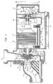
- Figure 1 is a cross-sectional view of a pump provided with the fan and motor housing according to the invention;
- Figure 2 is a frontal view of the fan according to the invention;
- Figure 2A is a cross-sectional view taken along arrows A-A of Figure 2;
- Figure 3 is a partial cross-sectional showing the fan and housing vents taken along lines 4-4 of Figure 1;
- Figure 3A is a cross-sectional view showing the motor housing vents, peeler tongue and fan taken along arrows A-A of Figure 3.
- Figure 3B is a partial view showing the fan and peeler tongue taken along line B-B of Figure 3.
- The pump apparatus of the invention will best be understood by reference to Figure 1. As illustrated, the apparatus includes a suction cover 11, suction inlet 12,
insert 13, and self-drainingchannel 14. A O-ring 16 is positioned between cover 11 andcasing 18 having anoutlet 19. Cover 11 andcasing 18 are mounted touniversal motor housing 20 by self taping screws in a standard manner. The universal motor includes a stator 22 and anarmature 24. Thearmature 24 includes acommutator 25, and ashaft 26 having a threadedend 27 and asplined end 28. The commutator brushes for the universal motor are located in thehousing 20 in a plane perpendicular to the cross-sectional view. - Threaded on
shaft end 27 is aninducerpeller 30 having mounted thereon arubber boot 31,ceramic ring 32, andmetal retaining ring 33 which form part of a mechanical seal. The other part of the mechanical seal includes acarbon seal ring 35,rubber boot 36,spring 37, and retainingcup 38. An O-ring 39 is positioned betweencup 38 andcasing 18.Inducerpeller 30 has twostep front surfaces inner surfaces insert 13 to provide an impeller seal wear ring surface to reduce recirculation leakage flow into the pump suction. The inducerpeller has avane 42 with avane portion 42a which extends forward along the axial portion of thefront shroud 40a, and sweeps back an angle of approximately 5° to 15° to the impeller axis to improve suction performance. - A
slinger 44 is mounted onshaft 26adjacent bearing hub 46 ofhousing 20.Bearings 48, rotatably mountshaft 26 inhub 46, andbearings 50 rotatably mount thesplined end 28 tohousing bearing surface 52, and bearing 50 is retained onhousing bearing surface 52 by means of strap 53. Afan 55 is spline mounted on thespline end 28 ofshaft 26. - An elastomeric
motor mounting foot 60, encloses acompartment 61, in which may be mounted acircuit board 62 for mountingelectrical components 62a, b for motor speed control. Backplate 65 encloses another compartment 66 in which may be mounted anothercircuit board 67 for mounting other of the electrical components 67a, b to control motor speed.Terminals housing 20 in known manner.Eack plate 65 may be metal to facilitate heat transfer thoughfins 65a fromcircuit board 67 which may be the high power circuit board of the control requiring the most heat dissipation. - In the preferred embodiment, cover 11, insert 13, casing 18,
housing 20,inducerpeller 30,fan 55, and mountingfoot 60 are made of plastic suitable for injection molding. - Figures 2 and 2A illustrate the motor fan according to the invention. The
fan 55 includes thirteenfull length blades 55a, thirteen short (splitter)vanes 55b, ahub 55c for pressing onto splined shaft, and arear fan shroud 55d. Therear fan shroud 55d has adiameter 55e which is less than thediameter 55f. As described in the Summary of the Invention, the splitter vanes equally spaced between the full length blades improves the effective cooling, and the reduced shroud diameter improves the air flow at the discharge of the fan as it exits the motor housing. - The fan features will be better understood by reference to Figure 3, which is a partial cross-sectional view taken along lines 4-4 of figure 1 to show the effect of air flow through the fan and vents.
Motor housing 20 hashousing vents fan 55.Rear fan shroud 55d has adiameter 55e shorter than theouter diameter 55f to facilitate air flow represented byarrows fan compartment 20c. In figure 3A, a peeler tongue 20d is shown invent 20a close to the outer diameter of the fan blades/vanes, and as shown in Figure 3B, themotor housing 20 peeler tongue 20d is skewed at anangle 84 of approximately fifteen degrees with respect to thefan blades 55a to further reduce motor/fan noise. Without skewing, the high and low pressure sides of the blades/vanes cause higher pressure pulsations or increased noise. - While the present invention has been disclosed in connection with a preferred embodiment thereof, it should be understood that there may be other embodiments which fall within the scope of the invention as defined by the following claims.
Claims (2)
- An electric machine including a motor in a motor housing (20) and a motor shaft (26) having an end (27) extending axially from one end of said motor housing (20),a pump housing (18) being mounted to said one end of said motor housing (20) and forming a chamberand an inducer impeller (30) being mounted on said one shaft end (27) for rotation within said chamber,characterized in that said motor housing (20) includes a fan (55) mounted on said shaft (26) and vents (20a, 20b), one having a skewed peeler tounge (20d) adjacent the outer diameter of said fan blades (55a) and vanes (55b), said peeler tounge (20d) being formed at an angle of approximately fifteen degrees with respect to the axis of one of the fan blades (55a).
- An electric machine according to claim 1, characterized in that the fan (55) has alternating fan blades (55a) and splitter vanes (55b), with the splitter vanes equally spaced between full length fan blades and a rear shroud (55d) with a diameter less then the outer diameter of the blades and vanes.
Priority Applications (1)
| Application Number | Priority Date | Filing Date | Title |
|---|---|---|---|
| EP95850062A EP0672833A3 (en) | 1990-10-31 | 1991-10-09 | High speed whirlpool pump. |
Applications Claiming Priority (2)
| Application Number | Priority Date | Filing Date | Title |
|---|---|---|---|
| US07/607,179 US5156535A (en) | 1990-10-31 | 1990-10-31 | High speed whirlpool pump |
| US607179 | 1990-10-31 |
Related Child Applications (1)
| Application Number | Title | Priority Date | Filing Date |
|---|---|---|---|
| EP95850062.1 Division-Into | 1991-10-09 |
Publications (3)
| Publication Number | Publication Date |
|---|---|
| EP0484305A2 EP0484305A2 (en) | 1992-05-06 |
| EP0484305A3 EP0484305A3 (en) | 1992-09-02 |
| EP0484305B1 true EP0484305B1 (en) | 1996-05-22 |
Family
ID=24431159
Family Applications (2)
| Application Number | Title | Priority Date | Filing Date |
|---|---|---|---|
| EP95850062A Withdrawn EP0672833A3 (en) | 1990-10-31 | 1991-10-09 | High speed whirlpool pump. |
| EP91850247A Expired - Lifetime EP0484305B1 (en) | 1990-10-31 | 1991-10-09 | High speed whirlpool pump |
Family Applications Before (1)
| Application Number | Title | Priority Date | Filing Date |
|---|---|---|---|
| EP95850062A Withdrawn EP0672833A3 (en) | 1990-10-31 | 1991-10-09 | High speed whirlpool pump. |
Country Status (8)
| Country | Link |
|---|---|
| US (1) | US5156535A (en) |
| EP (2) | EP0672833A3 (en) |
| JP (1) | JPH086716B2 (en) |
| KR (1) | KR950013778B1 (en) |
| CA (1) | CA2054556C (en) |
| DE (1) | DE69119698T2 (en) |
| ES (1) | ES2088479T3 (en) |
| TW (1) | TW197486B (en) |
Cited By (1)
| Publication number | Priority date | Publication date | Assignee | Title |
|---|---|---|---|---|
| US7507066B2 (en) | 2006-03-27 | 2009-03-24 | Koenig Kevin J | Pump header body and modular manifold |
Families Citing this family (84)
| Publication number | Priority date | Publication date | Assignee | Title |
|---|---|---|---|---|
| DE4237971B4 (en) † | 1992-11-11 | 2004-05-06 | Unaxis Deutschland Holding Gmbh | Vacuum pump with converter |
| JPH06159520A (en) * | 1992-11-13 | 1994-06-07 | Eagle Ind Co Ltd | Mechanical seal |
| DE4304149C1 (en) * | 1993-02-12 | 1994-09-08 | Grundfos As | Self-priming motor pump unit |
| US5701388A (en) * | 1994-12-22 | 1997-12-23 | Kohler Co. | Combined heater and pump |
| KR0134012B1 (en) * | 1995-06-29 | 1998-04-28 | 배순훈 | Warm water circulating pump with sub impeller |
| KR970001995A (en) * | 1995-06-29 | 1997-01-24 | 배순훈 | Hot Water Circulation Pump |
| KR100502727B1 (en) * | 1997-07-24 | 2005-12-26 | 엔 바이오 주식회사 | Method for manufacturing the ginseng extraction tea, and ginseng extraction tea manufactured by the same |
| CN1065327C (en) * | 1998-02-17 | 2001-05-02 | 鄢平安 | Sealer for impeller shaft |
| US6056506A (en) * | 1998-09-23 | 2000-05-02 | Emerson Electric Co. | Pump assembly for jetted tub |
| US6102657A (en) * | 1998-11-09 | 2000-08-15 | Hydrabaths, Inc. | Self-draining centrifugal pump having an improved inlet |
| US6149406A (en) * | 1999-09-07 | 2000-11-21 | Chang; Chin-Chin | Heat dissipating fan for an induction motor |
| US6428283B1 (en) * | 1999-09-16 | 2002-08-06 | 513004 B.C. Ltd. | Spa motor cooling method and apparatus |
| DE10050108A1 (en) * | 2000-10-09 | 2002-06-06 | Allweiler Ag | Rotor for turbine pump has bearing tube with bore to receive shaft and even number of vanes formed on it |
| US6561772B2 (en) * | 2001-04-03 | 2003-05-13 | Ametek, Inc. | Motor cooling fan housing with muffler |
| AUPR904301A0 (en) * | 2001-11-23 | 2001-12-20 | King, Peter John | Blower unit |
| US8337166B2 (en) * | 2001-11-26 | 2012-12-25 | Shurflo, Llc | Pump and pump control circuit apparatus and method |
| US7146659B2 (en) * | 2002-08-02 | 2006-12-12 | Mattson Jr Roy W | Hydromassage antimicrobial whirlpool bathtub |
| US6760931B1 (en) * | 2002-08-02 | 2004-07-13 | Roy W. Mattson, Jr. | Non-electric sanitation water vessel system |
| KR100508816B1 (en) * | 2002-08-28 | 2005-08-17 | 남재도 | Extraction process of mountain todok |
| US7101157B2 (en) * | 2002-11-19 | 2006-09-05 | Ebm-Papst Mulfingen Gmbh & Co. Kg | Cooling arrangement for an electromotor |
| US8540493B2 (en) | 2003-12-08 | 2013-09-24 | Sta-Rite Industries, Llc | Pump control system and method |
| US8480373B2 (en) | 2004-08-26 | 2013-07-09 | Pentair Water Pool And Spa, Inc. | Filter loading |
| US8043070B2 (en) | 2004-08-26 | 2011-10-25 | Pentair Water Pool And Spa, Inc. | Speed control |
| US8602745B2 (en) * | 2004-08-26 | 2013-12-10 | Pentair Water Pool And Spa, Inc. | Anti-entrapment and anti-dead head function |
| US8469675B2 (en) * | 2004-08-26 | 2013-06-25 | Pentair Water Pool And Spa, Inc. | Priming protection |
| US8019479B2 (en) | 2004-08-26 | 2011-09-13 | Pentair Water Pool And Spa, Inc. | Control algorithm of variable speed pumping system |
| US7686589B2 (en) | 2004-08-26 | 2010-03-30 | Pentair Water Pool And Spa, Inc. | Pumping system with power optimization |
| US7874808B2 (en) * | 2004-08-26 | 2011-01-25 | Pentair Water Pool And Spa, Inc. | Variable speed pumping system and method |
| US7845913B2 (en) | 2004-08-26 | 2010-12-07 | Pentair Water Pool And Spa, Inc. | Flow control |
| US7544041B2 (en) * | 2005-05-20 | 2009-06-09 | Wayne/Scott Fetzer Company | Pump with combined floating wear ring and liquid director |
| FR2888622B1 (en) * | 2005-07-18 | 2012-05-11 | Renault Sas | CHICANE WATER PUMP |
| JP4935048B2 (en) * | 2005-10-27 | 2012-05-23 | 日本電産株式会社 | Centrifugal fan |
| US7531092B2 (en) * | 2005-11-01 | 2009-05-12 | Hayward Industries, Inc. | Pump |
| US8186517B2 (en) * | 2005-11-01 | 2012-05-29 | Hayward Industries, Inc. | Strainer housing assembly and stand for pump |
| DE102005053343B3 (en) * | 2005-11-03 | 2007-06-28 | Treofan Germany Gmbh & Co.Kg | Cigarette package with inner wrapping of polymer film |
| US8182212B2 (en) * | 2006-09-29 | 2012-05-22 | Hayward Industries, Inc. | Pump housing coupling |
| GB0625571D0 (en) * | 2006-12-22 | 2007-02-07 | Electronica Products Ltd | Bathing pool |
| KR100837390B1 (en) * | 2007-01-05 | 2008-06-19 | 시종욱 | electric motion water meter |
| US8104110B2 (en) * | 2007-01-12 | 2012-01-31 | Gecko Alliance Group Inc. | Spa system with flow control feature |
| DE102007028398A1 (en) * | 2007-06-15 | 2008-12-24 | Ti Automotive (Neuss) Gmbh | Fuel pump with electronically commutated motor |
| FR2918576B1 (en) * | 2007-07-10 | 2009-10-09 | Inergy Automotive Systems Res | LIQUID SUPPLY SYSTEM FOR VEHICLE AND INTEGRATED PUMP / FILTER MODULE. |
| WO2009070599A1 (en) * | 2007-11-27 | 2009-06-04 | Emerson Electric Co. | Bi-directional cooling fan |
| JP5291363B2 (en) * | 2008-03-14 | 2013-09-18 | 三菱重工業株式会社 | pump |
| ES2688385T3 (en) | 2008-10-06 | 2018-11-02 | Pentair Water Pool And Spa, Inc. | Method for operating a vacuum release safety system |
| US8297920B2 (en) | 2008-11-13 | 2012-10-30 | Hayward Industries, Inc. | Booster pump system for pool applications |
| CN101871459B (en) * | 2009-04-24 | 2013-10-30 | 德昌电机(深圳)有限公司 | Discharge pump |
| US9556874B2 (en) | 2009-06-09 | 2017-01-31 | Pentair Flow Technologies, Llc | Method of controlling a pump and motor |
| US8436559B2 (en) | 2009-06-09 | 2013-05-07 | Sta-Rite Industries, Llc | System and method for motor drive control pad and drive terminals |
| US8564233B2 (en) | 2009-06-09 | 2013-10-22 | Sta-Rite Industries, Llc | Safety system and method for pump and motor |
| CN101929465B (en) * | 2009-06-19 | 2013-12-11 | 德昌电机(深圳)有限公司 | Drainage pump |
| NO333314B1 (en) * | 2009-07-03 | 2013-04-29 | Aker Subsea As | Turbo machine and impeller |
| KR101134970B1 (en) * | 2009-11-19 | 2012-04-09 | 현대자동차주식회사 | Electric water pump |
| KR101134968B1 (en) * | 2009-11-19 | 2012-04-09 | 현대자동차주식회사 | Electric water pump |
| KR101072327B1 (en) * | 2009-11-19 | 2011-10-11 | 현대자동차주식회사 | Electric water pump |
| KR101072328B1 (en) * | 2009-11-19 | 2011-10-11 | 현대자동차주식회사 | Electric water pump |
| KR101134969B1 (en) * | 2009-11-19 | 2012-04-09 | 현대자동차주식회사 | Method for manufacturing stator for electric water pump |
| US8308451B2 (en) * | 2009-12-07 | 2012-11-13 | Hamilton Sundstrand Corporation | Injection molded fan motor controller housing with advanced cooling features |
| IT1398030B1 (en) * | 2010-02-15 | 2013-02-07 | E M B Di Bergamaschini Alfonso | CENTRIFUGAL ELECTRIC PUMP FOR ASPIRATION OF FLUIDS AERIFORMS WITH SILENCER DEVICE. |
| US10030647B2 (en) * | 2010-02-25 | 2018-07-24 | Hayward Industries, Inc. | Universal mount for a variable speed pump drive user interface |
| SG191067A1 (en) | 2010-12-08 | 2013-08-30 | Pentair Water Pool & Spa Inc | Discharge vacuum relief valve for safety vacuum release system |
| WO2012087763A1 (en) | 2010-12-21 | 2012-06-28 | Pentair Water Pool And Spa, Inc. | Modular pump and filter system and method |
| CA2854162C (en) | 2011-11-01 | 2019-12-24 | Pentair Water Pool And Spa, Inc. | Flow locking system and method |
| TW201319394A (en) * | 2011-11-07 | 2013-05-16 | Assoma Inc | Improved structure of corrosion-protection housing of permanent magnet canned pump |
| JP5912424B2 (en) * | 2011-11-07 | 2016-04-27 | トヨタ自動車株式会社 | water pump |
| US9079128B2 (en) | 2011-12-09 | 2015-07-14 | Hayward Industries, Inc. | Strainer basket and related methods of use |
| US9885360B2 (en) | 2012-10-25 | 2018-02-06 | Pentair Flow Technologies, Llc | Battery backup sump pump systems and methods |
| AU2014340558A1 (en) * | 2013-10-22 | 2016-04-28 | Zodiac Pool Systems, Inc. | Systems including variable speed pumps for cleaning swimming pools and spas |
| ITRE20150032A1 (en) * | 2015-04-16 | 2016-10-16 | Annovi Reverberi Spa | MOTOR PUMP UNIT FOR HIGH PRESSURE WASHERS |
| WO2016205819A1 (en) * | 2015-06-19 | 2016-12-22 | Clarcor Engine Mobile Solutions, Llc | Brushless dc motor control and methods of operating a fuel pump |
| RU2623596C2 (en) * | 2015-12-02 | 2017-06-28 | Открытое акционерное общество "Красногорский завод "Электродвигатель" | Electric submersible pump |
| CN105757001A (en) * | 2016-04-26 | 2016-07-13 | 浙江理工大学 | Centrifugal pump with front pump cavity provided with parallelogram tooth-shaped structures |
| US10718337B2 (en) | 2016-09-22 | 2020-07-21 | Hayward Industries, Inc. | Self-priming dedicated water feature pump |
| US10851790B2 (en) * | 2016-09-27 | 2020-12-01 | W.S. Darley & Co. | Double volute end suction pump |
| RU2665740C1 (en) * | 2017-02-13 | 2018-09-04 | Акционерное общество "Красногорский завод "Электродвигатель" | Electric centrifugal pump |
| CN107143505B (en) * | 2017-06-20 | 2018-09-25 | 广东河海泵业机械有限公司 | A kind of in-service regulating device of follow-up motor type mechanical water pump blade angle |
| AU2018383657A1 (en) | 2017-12-15 | 2020-07-09 | Zodiac Pool Systems Llc | Inlet shrouds for fans used principally in water-circulation pumps of swimming pools and spas |
| JP7312558B2 (en) * | 2018-07-23 | 2023-07-21 | 株式会社荏原製作所 | Water supply device |
| CN109149839A (en) * | 2018-08-23 | 2019-01-04 | 浙江东欣节能科技有限公司 | Driving device |
| CN110439825A (en) * | 2019-07-11 | 2019-11-12 | 江苏大学 | A method of on-line monitoring sealing ring gap |
| US11193504B1 (en) | 2020-11-24 | 2021-12-07 | Aquastar Pool Products, Inc. | Centrifugal pump having a housing and a volute casing wherein the volute casing has a tear-drop shaped inner wall defined by a circular body region and a converging apex with the inner wall comprising a blocker below at least one perimeter end of one diffuser blade |
| USD986289S1 (en) | 2020-11-24 | 2023-05-16 | Aquastar Pool Products, Inc. | Centrifugal pump |
| USD946629S1 (en) | 2020-11-24 | 2022-03-22 | Aquastar Pool Products, Inc. | Centrifugal pump |
| DE112021003196T5 (en) * | 2021-04-01 | 2023-04-06 | Hanon Systems | AIR COMPRESSOR FOR VEHICLES |
| CN113513498B (en) * | 2021-07-16 | 2024-02-02 | 杭州南丰精工科技有限公司 | Water pump impeller with sealing structure |
Citations (4)
| Publication number | Priority date | Publication date | Assignee | Title |
|---|---|---|---|---|
| US353994A (en) * | 1886-12-07 | walker | ||
| DE3147501A1 (en) * | 1981-12-01 | 1983-06-09 | Licentia Patent-Verwaltungs-Gmbh, 6000 Frankfurt | Motor housing for electrical tools |
| DE3822897A1 (en) * | 1988-07-06 | 1990-01-11 | Webasto Ag Fahrzeugtechnik | Recirculating (circulating, return) pump |
| GB2220800A (en) * | 1988-07-09 | 1990-01-17 | Flux Geraete Gmbh | An electronically commutated brushless d.c. motor with the circuitry inside the casing |
Family Cites Families (30)
| Publication number | Priority date | Publication date | Assignee | Title |
|---|---|---|---|---|
| GB461227A (en) * | 1936-06-20 | 1937-02-12 | Petr Dmitrevskij | Improvements in or relating to the conveyance of boiling or gaseous liquids |
| US3013501A (en) * | 1956-12-27 | 1961-12-19 | Skoglund & Olson Ab | Centrifugal impeller |
| DE1075435B (en) * | 1957-05-27 | 1960-02-11 | Klein, Schanzlin & Becker A.G., Frankenthal (Pfalz) | Centrifugal pump without shaft seal |
| US3017071A (en) * | 1958-06-23 | 1962-01-16 | Trane Co | Turbine compressor assembly |
| US3272129A (en) * | 1963-12-18 | 1966-09-13 | Warner Machine Products Inc | Pumping system and pump therefor |
| FR1429964A (en) * | 1965-04-15 | 1966-02-25 | Shell Int Research | Pumping system |
| US3478689A (en) * | 1967-08-02 | 1969-11-18 | Borg Warner | Circulating pump |
| US3594102A (en) * | 1969-08-11 | 1971-07-20 | Domain Ind Inc | Water pump impeller having electrical insulation and corrosion-preventative features |
| US3644067A (en) * | 1970-05-25 | 1972-02-22 | Sperry Rand Corp | Power transmission |
| US3652183A (en) * | 1970-10-15 | 1972-03-28 | John E Pottharst Jr | Compressor |
| US3914072A (en) * | 1974-11-19 | 1975-10-21 | Weil Mclain Company Inc | Fluid pumping assembly |
| SU503046A2 (en) * | 1974-12-24 | 1976-02-15 | Специальное Конструкторско-Технологическое Бюро Герметичных И Скважинных Насосов | Impeller centrifugal pump |
| US4195473A (en) * | 1977-09-26 | 1980-04-01 | General Motors Corporation | Gas turbine engine with stepped inlet compressor |
| FR2428753A1 (en) * | 1978-06-14 | 1980-01-11 | Indesit | Centrifugal pump for dishwashing machine - has rotor blades extending axially beyond edge of shroud to separate entrained air |
| JPS5575590A (en) * | 1978-12-04 | 1980-06-06 | Hitachi Ltd | Radiator-fan |
| JPS552294U (en) * | 1979-06-25 | 1980-01-09 | ||
| US4597717A (en) * | 1982-09-30 | 1986-07-01 | Truline C.N.C., Inc. | Two-stage fluid pump |
| JPS59114493U (en) * | 1983-01-24 | 1984-08-02 | 冨田 博康 | circulating water pump |
| IT8422050V0 (en) * | 1984-06-04 | 1984-06-04 | Jacuzzi Europ | CENTRIFUGAL PUMP. |
| DE3520218A1 (en) * | 1984-06-08 | 1985-12-12 | Hitachi, Ltd., Tokio/Tokyo | IMPELLER FOR A RADIAL BLOWER |
| JPS6176799A (en) * | 1984-09-19 | 1986-04-19 | Aisin Seiki Co Ltd | Water pump for internal-combustion engine |
| JPS61244893A (en) * | 1985-04-22 | 1986-10-31 | Natl Aerospace Lab | Mechanism of supplying coolant to pump bearing |
| ES8708049A1 (en) * | 1985-06-03 | 1987-09-01 | Zaniewski Michel | Ventilation apparatus for rooms and draught inducer for chimney outlets. |
| JPS6228568A (en) * | 1985-07-31 | 1987-02-06 | Honda Motor Co Ltd | Mechanical seal for water pump |
| JPS62186097A (en) * | 1986-02-07 | 1987-08-14 | Matsushita Electric Ind Co Ltd | Motor-driven blower |
| US4998865A (en) * | 1988-07-11 | 1991-03-12 | Aisan Kogyo Kabushiki Kaisha | Brushless DC pump with enclosed circuit board |
| US4851724A (en) * | 1988-08-08 | 1989-07-25 | Power Flo Products Corp. | Pressure washer |
| JPH02153299A (en) * | 1988-12-05 | 1990-06-12 | Tokyo Gas Co Ltd | Shaft part cooling mechanism for ceramics fan |
| JPH02122198U (en) * | 1989-03-17 | 1990-10-05 | ||
| JPH0333565A (en) * | 1989-06-29 | 1991-02-13 | Mitsui Eng & Shipbuild Co Ltd | Mechanical seal for water pump |
-
1990
- 1990-10-31 US US07/607,179 patent/US5156535A/en not_active Expired - Lifetime
-
1991
- 1991-09-24 TW TW080107534A patent/TW197486B/zh active
- 1991-10-09 EP EP95850062A patent/EP0672833A3/en not_active Withdrawn
- 1991-10-09 DE DE69119698T patent/DE69119698T2/en not_active Expired - Fee Related
- 1991-10-09 EP EP91850247A patent/EP0484305B1/en not_active Expired - Lifetime
- 1991-10-09 ES ES91850247T patent/ES2088479T3/en not_active Expired - Lifetime
- 1991-10-28 KR KR1019910018956A patent/KR950013778B1/en not_active IP Right Cessation
- 1991-10-30 CA CA002054556A patent/CA2054556C/en not_active Expired - Lifetime
- 1991-10-30 JP JP3284690A patent/JPH086716B2/en not_active Expired - Fee Related
Patent Citations (4)
| Publication number | Priority date | Publication date | Assignee | Title |
|---|---|---|---|---|
| US353994A (en) * | 1886-12-07 | walker | ||
| DE3147501A1 (en) * | 1981-12-01 | 1983-06-09 | Licentia Patent-Verwaltungs-Gmbh, 6000 Frankfurt | Motor housing for electrical tools |
| DE3822897A1 (en) * | 1988-07-06 | 1990-01-11 | Webasto Ag Fahrzeugtechnik | Recirculating (circulating, return) pump |
| GB2220800A (en) * | 1988-07-09 | 1990-01-17 | Flux Geraete Gmbh | An electronically commutated brushless d.c. motor with the circuitry inside the casing |
Cited By (1)
| Publication number | Priority date | Publication date | Assignee | Title |
|---|---|---|---|---|
| US7507066B2 (en) | 2006-03-27 | 2009-03-24 | Koenig Kevin J | Pump header body and modular manifold |
Also Published As
| Publication number | Publication date |
|---|---|
| KR950013778B1 (en) | 1995-11-16 |
| DE69119698T2 (en) | 1996-10-31 |
| EP0484305A3 (en) | 1992-09-02 |
| DE69119698D1 (en) | 1996-06-27 |
| JPH04265492A (en) | 1992-09-21 |
| EP0672833A3 (en) | 1996-04-17 |
| EP0672833A2 (en) | 1995-09-20 |
| CA2054556A1 (en) | 1992-05-01 |
| US5156535A (en) | 1992-10-20 |
| TW197486B (en) | 1993-01-01 |
| JPH086716B2 (en) | 1996-01-29 |
| EP0484305A2 (en) | 1992-05-06 |
| ES2088479T3 (en) | 1996-08-16 |
| CA2054556C (en) | 1995-05-02 |
| KR920008357A (en) | 1992-05-27 |
Similar Documents
| Publication | Publication Date | Title |
|---|---|---|
| EP0484305B1 (en) | High speed whirlpool pump | |
| US6933638B2 (en) | Electric motor having a reverse air flow cooling system | |
| US6283726B1 (en) | Radial blower, particularly for heating and air conditioning systems in automobiles | |
| US7157818B2 (en) | Low noise ventilation system for electric motor | |
| EP0026997A1 (en) | Shroud arrangement for engine cooling fan | |
| US9543807B2 (en) | Electric motor | |
| KR20180054027A (en) | turbo compressor with separated paths for cooling air | |
| US6464471B1 (en) | High-efficiency motor/pump system for jetted bath/spas | |
| EP0651161A1 (en) | Device for cooling en electric motor for a turbo-fan | |
| US5855469A (en) | End seal design for blower | |
| KR20060005492A (en) | Wet and dry type motor without cooling fan | |
| US6296458B1 (en) | Electric fuel pump | |
| JPH02196191A (en) | Electric motor driven pump | |
| KR100378034B1 (en) | Motor fan | |
| JPH0882297A (en) | Canned motor pump | |
| KR100437037B1 (en) | Centrifugal fan of vacuum cleaner | |
| JP3509292B2 (en) | Generator | |
| JP4879408B2 (en) | Axial flow pump | |
| KR200246910Y1 (en) | Circulation pump for hot water boiler | |
| KR20000012685U (en) | Thrust disc ceramic washer shockproof device for boiler circulation pump. | |
| RU2141712C1 (en) | Electrical machine | |
| CN214366855U (en) | Combined fan and cooking utensil | |
| KR930004113Y1 (en) | Low-noise 2-step fan for vacuum cleaner | |
| JP2588987Y2 (en) | Dry type submersible motor pump | |
| WO2017175189A1 (en) | A water pump with separator and seal to protect rotor |
Legal Events
| Date | Code | Title | Description |
|---|---|---|---|
| PUAI | Public reference made under article 153(3) epc to a published international application that has entered the european phase |
Free format text: ORIGINAL CODE: 0009012 |
|
| AK | Designated contracting states |
Kind code of ref document: A2 Designated state(s): DE ES FR GB IT |
|
| PUAL | Search report despatched |
Free format text: ORIGINAL CODE: 0009013 |
|
| AK | Designated contracting states |
Kind code of ref document: A3 Designated state(s): DE ES FR GB IT |
|
| 17P | Request for examination filed |
Effective date: 19921102 |
|
| 17Q | First examination report despatched |
Effective date: 19940222 |
|
| GRAH | Despatch of communication of intention to grant a patent |
Free format text: ORIGINAL CODE: EPIDOS IGRA |
|
| GRAA | (expected) grant |
Free format text: ORIGINAL CODE: 0009210 |
|
| AK | Designated contracting states |
Kind code of ref document: B1 Designated state(s): DE ES FR GB IT |
|
| RIN1 | Information on inventor provided before grant (corrected) |
Inventor name: YEDIDIAH, SHMARIAHU Inventor name: BUDRIS, ALLAN ROGER Inventor name: HESSLER, WILLIAM DEWITT Inventor name: PATEL, RAMESH MAGAN |
|
| XX | Miscellaneous (additional remarks) |
Free format text: TEILANMELDUNG 95850062.1 EINGEREICHT AM 09/10/91. |
|
| REF | Corresponds to: |
Ref document number: 69119698 Country of ref document: DE Date of ref document: 19960627 |
|
| REG | Reference to a national code |
Ref country code: ES Ref legal event code: BA2A Ref document number: 2088479 Country of ref document: ES Kind code of ref document: T3 |
|
| ITF | It: translation for a ep patent filed |
Owner name: BUGNION S.P.A. |
|
| REG | Reference to a national code |
Ref country code: ES Ref legal event code: FG2A Ref document number: 2088479 Country of ref document: ES Kind code of ref document: T3 |
|
| ET | Fr: translation filed | ||
| PLBE | No opposition filed within time limit |
Free format text: ORIGINAL CODE: 0009261 |
|
| STAA | Information on the status of an ep patent application or granted ep patent |
Free format text: STATUS: NO OPPOSITION FILED WITHIN TIME LIMIT |
|
| 26N | No opposition filed | ||
| REG | Reference to a national code |
Ref country code: GB Ref legal event code: IF02 |
|
| PGFP | Annual fee paid to national office [announced via postgrant information from national office to epo] |
Ref country code: DE Payment date: 20081201 Year of fee payment: 18 |
|
| PGFP | Annual fee paid to national office [announced via postgrant information from national office to epo] |
Ref country code: ES Payment date: 20081027 Year of fee payment: 18 |
|
| PGFP | Annual fee paid to national office [announced via postgrant information from national office to epo] |
Ref country code: IT Payment date: 20081030 Year of fee payment: 18 |
|
| PGFP | Annual fee paid to national office [announced via postgrant information from national office to epo] |
Ref country code: FR Payment date: 20081018 Year of fee payment: 18 |
|
| PGFP | Annual fee paid to national office [announced via postgrant information from national office to epo] |
Ref country code: GB Payment date: 20081029 Year of fee payment: 18 |
|
| REG | Reference to a national code |
Ref country code: FR Ref legal event code: ST Effective date: 20100630 |
|
| PG25 | Lapsed in a contracting state [announced via postgrant information from national office to epo] |
Ref country code: FR Free format text: LAPSE BECAUSE OF NON-PAYMENT OF DUE FEES Effective date: 20091102 Ref country code: DE Free format text: LAPSE BECAUSE OF NON-PAYMENT OF DUE FEES Effective date: 20100501 |
|
| PG25 | Lapsed in a contracting state [announced via postgrant information from national office to epo] |
Ref country code: GB Free format text: LAPSE BECAUSE OF NON-PAYMENT OF DUE FEES Effective date: 20091009 |
|
| REG | Reference to a national code |
Ref country code: ES Ref legal event code: FD2A Effective date: 20110310 |
|
| PG25 | Lapsed in a contracting state [announced via postgrant information from national office to epo] |
Ref country code: IT Free format text: LAPSE BECAUSE OF NON-PAYMENT OF DUE FEES Effective date: 20091009 |
|
| PG25 | Lapsed in a contracting state [announced via postgrant information from national office to epo] |
Ref country code: ES Free format text: LAPSE BECAUSE OF NON-PAYMENT OF DUE FEES Effective date: 20110309 |
|
| PG25 | Lapsed in a contracting state [announced via postgrant information from national office to epo] |
Ref country code: ES Free format text: LAPSE BECAUSE OF NON-PAYMENT OF DUE FEES Effective date: 20091010 |