EP0484294B1 - Behälter für elektronische Teile - Google Patents
Behälter für elektronische Teile Download PDFInfo
- Publication number
- EP0484294B1 EP0484294B1 EP91830463A EP91830463A EP0484294B1 EP 0484294 B1 EP0484294 B1 EP 0484294B1 EP 91830463 A EP91830463 A EP 91830463A EP 91830463 A EP91830463 A EP 91830463A EP 0484294 B1 EP0484294 B1 EP 0484294B1
- Authority
- EP
- European Patent Office
- Prior art keywords
- cover
- dish
- container according
- resilient
- catch
- Prior art date
- Legal status (The legal status is an assumption and is not a legal conclusion. Google has not performed a legal analysis and makes no representation as to the accuracy of the status listed.)
- Expired - Lifetime
Links
Images

Classifications
-
- H—ELECTRICITY
- H10—SEMICONDUCTOR DEVICES; ELECTRIC SOLID-STATE DEVICES NOT OTHERWISE PROVIDED FOR
- H10P—GENERIC PROCESSES OR APPARATUS FOR THE MANUFACTURE OR TREATMENT OF DEVICES COVERED BY CLASS H10
- H10P72/00—Handling or holding of wafers, substrates or devices during manufacture or treatment thereof
- H10P72/10—Handling or holding of wafers, substrates or devices during manufacture or treatment thereof using carriers specially adapted therefor, e.g. front opening unified pods [FOUP]
- H10P72/19—Handling or holding of wafers, substrates or devices during manufacture or treatment thereof using carriers specially adapted therefor, e.g. front opening unified pods [FOUP] closed carriers
- H10P72/1914—Handling or holding of wafers, substrates or devices during manufacture or treatment thereof using carriers specially adapted therefor, e.g. front opening unified pods [FOUP] closed carriers characterised by locking systems
-
- B—PERFORMING OPERATIONS; TRANSPORTING
- B65—CONVEYING; PACKING; STORING; HANDLING THIN OR FILAMENTARY MATERIAL
- B65D—CONTAINERS FOR STORAGE OR TRANSPORT OF ARTICLES OR MATERIALS, e.g. BAGS, BARRELS, BOTTLES, BOXES, CANS, CARTONS, CRATES, DRUMS, JARS, TANKS, HOPPERS, FORWARDING CONTAINERS; ACCESSORIES, CLOSURES, OR FITTINGS THEREFOR; PACKAGING ELEMENTS; PACKAGES
- B65D43/00—Lids or covers for rigid or semi-rigid containers
- B65D43/02—Removable lids or covers
- B65D43/12—Removable lids or covers guided for removal by sliding
-
- H—ELECTRICITY
- H05—ELECTRIC TECHNIQUES NOT OTHERWISE PROVIDED FOR
- H05K—PRINTED CIRCUITS; CASINGS OR CONSTRUCTIONAL DETAILS OF ELECTRIC APPARATUS; MANUFACTURE OF ASSEMBLAGES OF ELECTRICAL COMPONENTS
- H05K13/00—Apparatus or processes specially adapted for manufacturing or adjusting assemblages of electric components
- H05K13/0084—Containers and magazines for components, e.g. tube-like magazines
-
- H—ELECTRICITY
- H10—SEMICONDUCTOR DEVICES; ELECTRIC SOLID-STATE DEVICES NOT OTHERWISE PROVIDED FOR
- H10P—GENERIC PROCESSES OR APPARATUS FOR THE MANUFACTURE OR TREATMENT OF DEVICES COVERED BY CLASS H10
- H10P72/00—Handling or holding of wafers, substrates or devices during manufacture or treatment thereof
- H10P72/10—Handling or holding of wafers, substrates or devices during manufacture or treatment thereof using carriers specially adapted therefor, e.g. front opening unified pods [FOUP]
- H10P72/19—Handling or holding of wafers, substrates or devices during manufacture or treatment thereof using carriers specially adapted therefor, e.g. front opening unified pods [FOUP] closed carriers
- H10P72/1916—Handling or holding of wafers, substrates or devices during manufacture or treatment thereof using carriers specially adapted therefor, e.g. front opening unified pods [FOUP] closed carriers characterised by sealing arrangements
Definitions
- the present invention relates to a container, particularly for electronic equipment, of the type including a dish-like body and a flat cover.
- the dish-like body of the container according to the invention has a plurality of catch projections on opposite side walls
- the cover has a plurality of resilient appendages on two opposed portions of its periphery for engaging the corresponding catch projections of the dish-like body in order to clamp the cover to the body.
- An annular seal of elastomeric material is preferably interposed between the dish-like body and the cover.
- the cover can repeatedly be removed and replaced quickly by virtue of the resilient engagement between the catch projections of the dish-like body and the resilient appendages of the cover.
- the catch projections of the dish-like body preferably have sloping portions for cooperating with the resilient appendages of the cover as the flat cover slides relative to the dish-like body so as to compress the annular seal resiliently.
- the annular seal is therefore squashed uniformly, thus ensuring that the container is closed hermetically. Moreover, the cover is not damaged when it is removed and can therefore be reused.
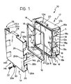
- a metal container for electronic components includes a quadrangular dish-like aluminium body 12, a flat sheet-metal cover 14 and an annular seal 16 of elastomeric material which is interposed between the body 12 and the cover 14 and fitted in an annular groove 16a in a flat edge B of the body 12.
- the body 12 has two opposed, parallel flat walls 12a from which six shaped external catch projections 18 project outwardly in opposed pairs adjacent the edge B.
- Each catch projection 18 is integral with the dish-like body 12, is substantially parallelepipedal and, on its side which faces away from the edge B, defines a surface S including a sloping surface portion 18a and a flat portion 18b which is parallel to the plane in which the cover 14 lies on the edge B of the body 12.
- a third side wall 12b of the dish-like body 12 has an auxiliary catch projection 20 adjacent the edge B and a fourth wall 12c has a projection 22 with a threaded hole 24, the axis of which is substantially perpendicular to a base wall 12d of the dish-like body 12.
- the flat cover 14 has two parallel sides 14a which correspond to the parallel sides 12a of the dish-like body 12 and have L-shaped resilient appendages 26, each defining a first portion 26a substantially perpendicular to the plane of the cover and a second portion 26b which has a substantially open, circular cross-section and is adapted to act as a resilient element, as will become clear from the following description.
- a third side 14b of the cover 14 has an auxiliary resilient appendage 28 substantially similar to the appendages 26 and a fourth side 14c of the cover 14 has an appendage 30 which is disposed in the plane of the cover and has a through-hole 30a.
- the appendages 26 which project from the plane of the cover 14, and the auxiliary appendage 28, are disposed on the cover 14 in positions corresponding to those of the catch projections 18 and of the auxiliary catch projection 20 of the dish-like body 12, respectively.
- the cover 14 can thus be fitted on the dish-like body 12 quickly according to the sequence shown in Figures 2, 3 and 4.
- a first step ( Figure 2), the resilient appendages 26 are inserted in the spaces between the catch projections 18 so that the flat portion of the cover 14, indicated 14d in the drawings, can contact the annular seal 16 fitted in the groove 16a of the dish-like body 12.
- this configuration shown in Figure 3
- the cover 14 In this operative configuration, the maximum squashing of the annular seal 16 and the best seal against external agents are achieved.
- it may be fixed to the dish-like body 12 by a screw 32 inserted through the hole 30a in the appendage 30 of the cover 14 and screwed into the threaded hole 24 in the body 12.
Landscapes
- Engineering & Computer Science (AREA)
- Manufacturing & Machinery (AREA)
- Microelectronics & Electronic Packaging (AREA)
- Mechanical Engineering (AREA)
- Closures For Containers (AREA)
- Casings For Electric Apparatus (AREA)
- Thermally Insulated Containers For Foods (AREA)
- Telephone Function (AREA)
- Piezo-Electric Or Mechanical Vibrators, Or Delay Or Filter Circuits (AREA)
- Packaging Frangible Articles (AREA)
Claims (7)
- Behälter, insbesondere für Elektronikausrüstung, in Art eines schalenähnlichen Körpers (12) und einer flachen Abdeckung (14),
dadurch gekennzeichnet,
daß der schalenähnliche Körper (12) eine Vielzahl von Verschlußvorsprüngen (18) an gegenüberliegenden Seitenwänden (12a) aufweist und daß die Abdeckung (14) eine Vielzahl elastischer Ansätze (26) an zwei gegenüberliegenden Abschnitten (14a) ihres Umfangs zum Eingreifen in den entsprechenden Verschlußvorsprüngen (18) des schalenähnlichen Körpers (12) aufweist, um die Abdeckung (14) an dem Körper (12) festzuklemmen. - Behälter nach Anspruch 1,
dadurch gekennzeichnet,
daß eine umlaufende Dichtung (16) aus Elastomer-Material zwischen dem schalenähnlichen Körper (12) und der Abdeckung (14) eingefügt ist. - Behälter nach Anspruch 2,
dadurch gekennzeichnet,
daß die Verschlußvorsprünge (18) des schalenähnlichen Körpers (12) geneigte Abschnitte (18a) zum Zusammenwirken mit den elastischen Ansätzen (26, 26b) der Abdeckung (14) aufweisen, wenn die Abdeckung (14) relativ zu dem schalenähnlichen Körper (12) gleitet, um die umlaufende Dichtung (16) elastisch zusammen zu drücken. - Behälter nach irgendeinem der vorhergehenden Ansprüche,
dadurch gekennzeichnet,
daß die Verschlußvorsprünge (18) an gegenüberliegenden, parallelen Seitenwanden (12a) des schalenähnlichen Körpers (12) angeordnet sind und daß der Körper (12) zumindest einen Hilfsverschlußvorsprung (20) an einer dritten, in bezug auf die gegenüberliegenden Seitenwänden (12a) senkrechten Seitenwand (12b) zum Zusammenwirken mit einem elastischen Hilfsansatz (28) an der Abdeckung (14) aufweist. - Behälter nach Anspruch 2,
dadurch gekennzeichnet,
daß jeder Verschlußvorsprung (18) des schalenähnlichen Körpers (12) korrespondierend zu einem Eckbereich (B) des Körpers (12) angeordnet ist und eine Fläche (S) aufweist, die weg von der Abdeckung (14) gerichtet ist und einen flachen Abschnitt (18a) umfasst, der relativ zu der Ebene geneigt ist, in der die Abdeckung (14) liegt, und mit einem flachen Abschnitt (18b), der parallel zu dieser Ebene verläuft, verbunden ist. - Behälter nach irgendeinem der vorhergehenden Ansprüche,
dadurch gekennzeichnet,
daß jeder elastische Vorsprung (26) der Abdeckung (14) im wesentlichen L-förmig ist und einen zu der Abdeckung (14) senkrechten ersten Abschnitt (26a) und einen zweiten gebogenen, elastischen Abschnitt (26b) aufweist. - Behälter nach irgendeinem der vorhergehenden Ansprüche,
dadurch gekennzeichnet,
daß Schraub- und Gewinde-Klemmelemente (32, 30, 30a, 24, 22) zwischen der Abdeckung (14) und dem schalenähnlichen Körper (12) eingefügt sind.
Applications Claiming Priority (2)
| Application Number | Priority Date | Filing Date | Title |
|---|---|---|---|
| IT53351U IT220659Z2 (it) | 1990-10-31 | 1990-10-31 | Contenitore per apparecchiature elettroniche |
| IT5335190U | 1990-10-31 |
Publications (2)
| Publication Number | Publication Date |
|---|---|
| EP0484294A1 EP0484294A1 (de) | 1992-05-06 |
| EP0484294B1 true EP0484294B1 (de) | 1993-10-27 |
Family
ID=11282057
Family Applications (1)
| Application Number | Title | Priority Date | Filing Date |
|---|---|---|---|
| EP91830463A Expired - Lifetime EP0484294B1 (de) | 1990-10-31 | 1991-10-29 | Behälter für elektronische Teile |
Country Status (4)
| Country | Link |
|---|---|
| EP (1) | EP0484294B1 (de) |
| DE (1) | DE69100562T2 (de) |
| ES (1) | ES2046036T3 (de) |
| IT (1) | IT220659Z2 (de) |
Cited By (2)
| Publication number | Priority date | Publication date | Assignee | Title |
|---|---|---|---|---|
| KR20230123291A (ko) * | 2022-02-16 | 2023-08-23 | 정규철 | 슬라이드 방식의 개폐 구조를 갖는 포장용기 |
| WO2024081199A1 (en) * | 2022-10-10 | 2024-04-18 | Entegris, Inc. | Storage container for freezing, thawing, and shipping |
Families Citing this family (14)
| Publication number | Priority date | Publication date | Assignee | Title |
|---|---|---|---|---|
| DE4314920C2 (de) * | 1993-05-05 | 1998-03-26 | Stucki Kunststoffwerk | Behälterverschluß für einen mit Deckel versehenen, aus Kunststoff hergestellten Behälter |
| US5474180A (en) * | 1994-03-07 | 1995-12-12 | Specialized Health Products, Inc. | Container assembly for transport and disposal of medical materials |
| US5570783A (en) * | 1994-03-07 | 1996-11-05 | Specialized Health Products, Inc. | Apparatus and methods for transporting and discarding medical materials |
| US5630506A (en) * | 1994-03-07 | 1997-05-20 | Specialized Health Products, Inc. | Apparatus and method for transporting and discarding medical materials |
| IT234436Y1 (it) * | 1994-06-15 | 2000-03-09 | Borghini Fabio | Contenitore per la spedizione e il trasporto di oggetti, in partcolare adatto per essere chiuso mediante sigilli. |
| US5996831A (en) * | 1996-11-07 | 1999-12-07 | Sphinx Elektronik Gmbh | Closure device |
| DE19646009C2 (de) * | 1996-11-07 | 1999-07-01 | Sphinx Elektronik Gmbh | Verschlußvorrichtung |
| US5848692A (en) * | 1997-06-18 | 1998-12-15 | Specialized Health Products, Inc. | Unimold container for discarding medical material |
| EP0987750B1 (de) * | 1998-04-06 | 2006-11-15 | Dainichi Shoji K.K. | Behälter |
| ES2404982B1 (es) * | 2011-11-15 | 2014-09-10 | Jorge Horacio SÁNCHEZ TABOAS | Sistema de cierre hermético para recipiente y recipiente que incorpora dicho sistema de cierre y uso del mencionado recipiente |
| CN104002560A (zh) * | 2013-02-25 | 2014-08-27 | 泓瀚科技股份有限公司 | 墨盒开闭结构 |
| DE202013102827U1 (de) * | 2013-06-28 | 2014-09-29 | Rehau Ag + Co | Rohrreinigungsformteil |
| DE102019100951A1 (de) | 2019-01-15 | 2020-07-16 | Osram Opto Semiconductors Gmbh | Aufbewahrungsvorrichtung |
| CN119460434A (zh) * | 2024-11-19 | 2025-02-18 | 苏州一航电子科技股份有限公司 | 一种滑动解锁式密封盖体 |
Family Cites Families (1)
| Publication number | Priority date | Publication date | Assignee | Title |
|---|---|---|---|---|
| DE7039265U (de) * | 1970-10-23 | 1971-02-18 | Bihler-Elektroanlagen H Bihler Gmbh & Co | Installationsbehalter, insbesondere Rangierverteilerkasten |
-
1990
- 1990-10-31 IT IT53351U patent/IT220659Z2/it active IP Right Grant
-
1991
- 1991-10-29 ES ES91830463T patent/ES2046036T3/es not_active Expired - Lifetime
- 1991-10-29 DE DE91830463T patent/DE69100562T2/de not_active Expired - Fee Related
- 1991-10-29 EP EP91830463A patent/EP0484294B1/de not_active Expired - Lifetime
Cited By (4)
| Publication number | Priority date | Publication date | Assignee | Title |
|---|---|---|---|---|
| KR20230123291A (ko) * | 2022-02-16 | 2023-08-23 | 정규철 | 슬라이드 방식의 개폐 구조를 갖는 포장용기 |
| KR20240068616A (ko) * | 2022-02-16 | 2024-05-17 | 정규철 | 슬라이드 방식의 개폐 구조를 갖는 포장용기 |
| KR102672488B1 (ko) | 2022-02-16 | 2024-06-04 | 정규철 | 슬라이드 방식의 개폐 구조를 갖는 포장용기 |
| WO2024081199A1 (en) * | 2022-10-10 | 2024-04-18 | Entegris, Inc. | Storage container for freezing, thawing, and shipping |
Also Published As
| Publication number | Publication date |
|---|---|
| IT9053351U1 (it) | 1992-05-01 |
| IT9053351V0 (it) | 1990-10-31 |
| DE69100562T2 (de) | 1994-04-14 |
| ES2046036T3 (es) | 1994-01-16 |
| IT220659Z2 (it) | 1993-10-08 |
| EP0484294A1 (de) | 1992-05-06 |
| DE69100562D1 (de) | 1993-12-02 |
Similar Documents
| Publication | Publication Date | Title |
|---|---|---|
| EP0484294A1 (de) | Behälter für elektronische Teile | |
| US6274808B1 (en) | EMI shielding enclosure | |
| US4215796A (en) | Radio frequency shield structure | |
| US4505403A (en) | Weatherproof electrical receptacle cover | |
| US4158757A (en) | Enclosure seal | |
| AU638904B2 (en) | Improved electrical load center | |
| US5630632A (en) | Quarter turn latch | |
| US4541538A (en) | Wiring device covers | |
| US4102471A (en) | Switch guard assembly | |
| US3596139A (en) | Improved electronic component assembly cylindrical shell housing with inner peripheral radiating fin circuit board fastener means | |
| US3477609A (en) | Plastic box having snap cover with seal | |
| CA2226798A1 (en) | Tool case | |
| US6044773A (en) | Work station for holding objects | |
| US6317317B1 (en) | Insertion cartridge for hard disc of portable computer | |
| US4529834A (en) | Formed metallic wiring box | |
| US5770328A (en) | Battery packaging system and clip for same | |
| AU638647B2 (en) | Latch assembly for an electrical load center door, and method of assembly thereof | |
| JP3292800B2 (ja) | 密封容器のクランプ構造 | |
| US5432298A (en) | Apparatus for covering electrical sockets or switches | |
| US7423216B2 (en) | Dual action sealing gasket and use thereof in an electrical housing assembly | |
| US5988391A (en) | Electronic parts casing | |
| GB2591884A (en) | A washer for a fixing for use on an enclosure | |
| JP2500662B2 (ja) | 積み重ね式スタッド | |
| JPS6338484Y2 (de) | ||
| GB2076873A (en) | Wall copings |
Legal Events
| Date | Code | Title | Description |
|---|---|---|---|
| PUAI | Public reference made under article 153(3) epc to a published international application that has entered the european phase |
Free format text: ORIGINAL CODE: 0009012 |
|
| AK | Designated contracting states |
Kind code of ref document: A1 Designated state(s): DE ES FR GB |
|
| 17P | Request for examination filed |
Effective date: 19920518 |
|
| 17Q | First examination report despatched |
Effective date: 19921229 |
|
| GRAA | (expected) grant |
Free format text: ORIGINAL CODE: 0009210 |
|
| AK | Designated contracting states |
Kind code of ref document: B1 Designated state(s): DE ES FR GB |
|
| REF | Corresponds to: |
Ref document number: 69100562 Country of ref document: DE Date of ref document: 19931202 |
|
| REG | Reference to a national code |
Ref country code: ES Ref legal event code: FG2A Ref document number: 2046036 Country of ref document: ES Kind code of ref document: T3 |
|
| ET | Fr: translation filed | ||
| PLBE | No opposition filed within time limit |
Free format text: ORIGINAL CODE: 0009261 |
|
| STAA | Information on the status of an ep patent application or granted ep patent |
Free format text: STATUS: NO OPPOSITION FILED WITHIN TIME LIMIT |
|
| 26N | No opposition filed | ||
| PGFP | Annual fee paid to national office [announced via postgrant information from national office to epo] |
Ref country code: GB Payment date: 19970918 Year of fee payment: 7 |
|
| PGFP | Annual fee paid to national office [announced via postgrant information from national office to epo] |
Ref country code: DE Payment date: 19970922 Year of fee payment: 7 |
|
| PGFP | Annual fee paid to national office [announced via postgrant information from national office to epo] |
Ref country code: ES Payment date: 19971016 Year of fee payment: 7 |
|
| PGFP | Annual fee paid to national office [announced via postgrant information from national office to epo] |
Ref country code: FR Payment date: 19971030 Year of fee payment: 7 |
|
| PG25 | Lapsed in a contracting state [announced via postgrant information from national office to epo] |
Ref country code: GB Free format text: LAPSE BECAUSE OF NON-PAYMENT OF DUE FEES Effective date: 19981029 |
|
| PG25 | Lapsed in a contracting state [announced via postgrant information from national office to epo] |
Ref country code: ES Free format text: LAPSE BECAUSE OF NON-PAYMENT OF DUE FEES Effective date: 19981030 |
|
| GBPC | Gb: european patent ceased through non-payment of renewal fee |
Effective date: 19981029 |
|
| PG25 | Lapsed in a contracting state [announced via postgrant information from national office to epo] |
Ref country code: FR Free format text: LAPSE BECAUSE OF NON-PAYMENT OF DUE FEES Effective date: 19990630 |
|
| REG | Reference to a national code |
Ref country code: FR Ref legal event code: ST |
|
| PG25 | Lapsed in a contracting state [announced via postgrant information from national office to epo] |
Ref country code: DE Free format text: LAPSE BECAUSE OF NON-PAYMENT OF DUE FEES Effective date: 19990803 |
|
| REG | Reference to a national code |
Ref country code: ES Ref legal event code: FD2A Effective date: 19991113 |