EP0484282A2 - Procédé et appareil d'analyse par moyen des ondes thermiques - Google Patents
Procédé et appareil d'analyse par moyen des ondes thermiques Download PDFInfo
- Publication number
- EP0484282A2 EP0484282A2 EP91810847A EP91810847A EP0484282A2 EP 0484282 A2 EP0484282 A2 EP 0484282A2 EP 91810847 A EP91810847 A EP 91810847A EP 91810847 A EP91810847 A EP 91810847A EP 0484282 A2 EP0484282 A2 EP 0484282A2
- Authority
- EP
- European Patent Office
- Prior art keywords
- laser
- frequency
- laser beam
- partial beams
- detector
- Prior art date
- Legal status (The legal status is an assumption and is not a legal conclusion. Google has not performed a legal analysis and makes no representation as to the accuracy of the status listed.)
- Granted
Links
Images
Classifications
-
- G—PHYSICS
- G01—MEASURING; TESTING
- G01N—INVESTIGATING OR ANALYSING MATERIALS BY DETERMINING THEIR CHEMICAL OR PHYSICAL PROPERTIES
- G01N25/00—Investigating or analyzing materials by the use of thermal means
- G01N25/72—Investigating presence of flaws
-
- G—PHYSICS
- G01—MEASURING; TESTING
- G01N—INVESTIGATING OR ANALYSING MATERIALS BY DETERMINING THEIR CHEMICAL OR PHYSICAL PROPERTIES
- G01N21/00—Investigating or analysing materials by the use of optical means, i.e. using sub-millimetre waves, infrared, visible or ultraviolet light
- G01N21/17—Systems in which incident light is modified in accordance with the properties of the material investigated
- G01N21/171—Systems in which incident light is modified in accordance with the properties of the material investigated with calorimetric detection, e.g. with thermal lens detection
-
- G—PHYSICS
- G01—MEASURING; TESTING
- G01N—INVESTIGATING OR ANALYSING MATERIALS BY DETERMINING THEIR CHEMICAL OR PHYSICAL PROPERTIES
- G01N21/00—Investigating or analysing materials by the use of optical means, i.e. using sub-millimetre waves, infrared, visible or ultraviolet light
- G01N21/17—Systems in which incident light is modified in accordance with the properties of the material investigated
- G01N2021/1738—Optionally different kinds of measurements; Method being valid for different kinds of measurement
- G01N2021/1742—Optionally different kinds of measurements; Method being valid for different kinds of measurement either absorption or reflection
Definitions
- the invention relates to a method for thermal wave analysis according to the preamble of claim 1 and arrangements for thermal wave analysis.
- the contactless and non-destructive method according to the invention has its main field of application in coating technology as a test method for quality control.
- a known method according to A. Rosencwaig is that a periodically intensity-modulated pump laser excites a thermal wave in the layer, which in turn modulates the refractive index locally, so that the modulated optical reflection (MOR) can be measured with a second so-called test laser beam (US Pat. No. 4,579,463) ).
- the signal processing is preferably carried out using lock-in technology in order to detect the phase and amplitude of the MOR.
- This method requires the use of 2 lasers of different wavelengths and, in order to ensure a quantitatively evaluable reflection signal, the concentric arrangement of the pump and test beam with perpendicular incidence on the layer.
- the test beam radius should be at most half of the pump beam radius.
- the invention has for its object to reduce the technical effort for performing the optical thermal wave analysis and to lower the sensitivity limit.
- the object is achieved according to the invention with a method for thermal wave analysis according to the features in claim 1.
- the basic idea of the invention is based on the fact that the object excitation and the detection of the transmission or reflection modulated by the object is carried out with a single optical beam directed at the object, the intensity of which is modulated with two frequencies.
- This modulation can be generated by a modulatable light source to which both modulation frequencies are impressed, by splitting a beam into two partial beams, modulating them separately and then combining them into one beam, or by using two separate, individually modulated light sources and combining the so created ones Partial beams.
- the possibility of interference of the partial beams with one another must be excluded in order to suppress an undesired generation of mixed products of both frequencies.
- the thermal wave reaction triggered by the additive two-frequency modulation according to the invention which acts effectively as an excitation for the object with the arithmetic mean of the two frequencies, is found in the beam portion leaving the object again in the form of mixed products of the two frequencies which are in the excitation beam due to the addivity the modulation are not included and can therefore be detected using a frequency-selective device.
- the difference frequency of the two frequencies modulating the beam is expediently used to detect the transmission or reflection modulated by the object, since it can easily be placed in low-frequency ranges, which has an advantageous effect on the electronic measuring effort.
- For the also possible evaluation of the Sum frequency from the two modulation frequencies requires an analysis of the phase offset in addition to the evaluation of the intensity amplitude.
- the intensities used to form the difference are expediently adjusted in the measuring process by an element of controllable transmission in such a way that the time average of the difference in the measuring signals is identical to zero.
- This measuring principle has the advantage that that portion of the intensity noise of the light source is suppressed which exceeds the shot noise of the photon current of the detectors and of which, when measuring the intensity of the beam portion influenced by the object, those contributions from the ranges of the detected mixing frequencies as well as disruptive effects the modulation frequencies shifted around the mixed frequency.
- the limit sensitivity is no longer determined by the specific noise properties of the light source, but only by the intensity of the light source and the noise properties of the detection system.
- comparatively strongly noisy light sources e.g. B. Laser of low stability, can be used for the measuring method.
- the field of application of the method according to the invention can also be expanded to include thermal wave reactions of the object which essentially do not cause any modulation of the transmission or reflectivity, but rather lead to position and shape modulations of the beam. This is done by inserting diaphragms at a suitable point in the course of the beam influenced by the object, which cut the beam depending on the position and / or shape.
- apertures can be used in this beam path in a conjugate object plane to limit the measuring field Find.
- the arrangement according to claim 14 can advantageously be realized in that a laser diode is used as the light source, to which both modulation frequencies are supplied.
- a laser diode is used as the light source, to which both modulation frequencies are supplied.
- an optical system equivalent to the objective and the measuring detector are arranged downstream of the object or a beam-coupling element for the reflected beam component is arranged in the beam path after the double-used objective.
- a differential amplifier is arranged in the electronic evaluation section in front of the frequency-selective device, which is connected at its inverting input to a reference detector, the input signal of which is decoupled from the unaffected beam of the laser source by means of a semi-transparent mirror.
- the laser source can expediently be composed of an unmodulated laser and a modulating optical element, to which the two modulation frequencies are fed.
- the modeling optical element is advantageously an acousto-optical modulator.
- the arrangement according to the invention as claimed in claim 21 can be advantageously designed in that heath partial beams are initially linearly polarized in the same direction, in each of the partial beam paths a glass plate positioned at the Brewster angle is arranged such that the reflected beam component of the glass plates runs along a common axis, on this A ⁇ / 2 plate is arranged between the glass plates and a reference detector is arranged outside the glass plate distance in the direction of the reflected beam components, and a ⁇ / 2 plate is present in one of the partial beam paths between the glass plate and the beam splitter cube.
- the measuring detector is arranged on said common axis of the glass plates opposite the reference detector and the beam splitter cube is designed in the form of a polarization switch.
- the beam splitter cube is designed in the form of a polarization switch.
- the third arrangement according to the invention according to claim 26 is advantageously supplemented in that a semitransparent mirror is arranged between the beam splitter cube and the objective, which (analogous to the first arrangement according to the invention) couples out a beam portion of the incident laser beam onto a reference detector, the measurement detector and reference detector signal being the inputs of one of the frequency-selective device upstream differential amplifier are supplied.
- the beam splitter cube is also a polarization switch and a polarization filter with the same orientation is in front of the measuring and reference detectors in order to separate out parts of the laser beam for registration that allow the phase offset between the stimulating modulation signal and the response signal to be determined .
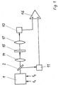
- the laser beam has an intensity modulation spectrum with two discrete frequencies f 1 and f 2.
- a laser diode 1 ' is expediently used, to which both frequencies f 1 and f 2 are supplied.
- the object 15 experiences an effective excitation with the arithmetic mean of the frequencies f 1 and f 2 and shows a thermal wave reaction that contains mixed products of the frequencies f 1 and f 2 in the beam portion leaving the object, which are not contained in the incident laser beam due to the additivity of the excitation.
- the thermal wave reaction of the object 15 is transmitted according to FIG. 1 in transmission via an optical system 17 equivalent to the lens 14 to a measuring detector 10, the signal of which - provided an extremely low-noise laser source 1 is required - for generating the amplitude of the mixed frequency by means of a frequency-selective device for evaluation is sufficient without the elements of semi-transparent mirror 2, reference detector 11 and differential amplifier 16 are absolutely necessary.
- this reference branch which is shown in FIG. 1 and which decouples a portion of the laser beam directed at the object 15, the laser noise can be effectively suppressed if the incoming measurement and reference signals are compared to the mean difference in time zero.
- the differential amplifier signal for evaluation in the frequency-selective device can also be used to compare the intensities of the measurement and reference signals, which are not shown in FIG. 1.
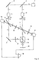
- FIG. 2 shows the beam guidance for a reflection mode of operation when using a cw laser as laser source 1 and two acousto-optical modulators 4 and 5 in two partial beams for intensity modulation that are produced by beam splitting.
- the laser beam polarized perpendicular to the plane of the drawing is converted into two equal in intensity by the use of a semitransparent mirror 2 and a deflecting mirror 3 Shares split, and the resulting partial beams pass through the modulators 4 and 5. After their modulation, the partial beams hit a glass plate 6 and 7, respectively.
- the glass plates 6 and 7 are each oriented at the Brewster angle and arranged so that the reflected beam components Glass plates 6 and 7 run along a common axis, on which a ⁇ / 2 plate 8 is arranged between the glass plates 6 and 7, so that the reflected beam portion of the glass plate 6 passes through the glass plate 7 after polarization rotation by 90 ° and with that of the glass plate 7 reflected beam portion falls on the reference detector 11 also located on said common axis.
- the beam portion passing through the glass plate 6 is deflected by a further mirror 3, passes through a ⁇ / 2 plate 9 and, together with the beam portion of the second partial beam that has passed through the glass plate 7, is transmitted as a beam by means of the lens via a beam splitter cube 13 designed as a polarization switch 14 focused on the object 15.
- the beam reflected by the object 15 is split again in the beam splitter cube 13 in accordance with the two directions of polarization contained.
- the beam components generated in this way run in the opposite direction through the paths previously traveled by the two partial beams to the respective glass plate 6 or 7.
- the component reflected on glass plate 7 passes through the ⁇ / 2 plate 8 and the glass plate 6 and becomes together with that on the glass plate 6 reflected portion along the above common axis of the glass plates 6 and 7 out on the measuring detector 10.
- the measurement and reference signals are in turn subtracted from one another in a differential amplifier 16.
- the control signal for the already indicated intensity adjustment between the measuring and reference detectors 10 and 11 is also obtained, with which the element with controllable transmission 12 optically adjusts the intensity to the time average zero.
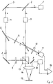
- the beam components reflected on the object 15 it is not possible for the beam components reflected on the object 15 to affect the laser source 1 to exclude.
- Fig. 3 therefore modifies this variant by moving the objective 14 with its objective axis out of the excitation beam direction after the identical production of the two partial beams and their combination in the beam splitter cube 13, so that the excitation and reaction beam of the object 15 are center-symmetrical with respect to the objective axis and reaction beam reflected on the object 15 enters the measuring detector 10 via a mirror 3. All other elements and their functions remain as described for FIG. 2.
- FIGS. 2 and 3 in which two partial beams are generated by splitting the light from a laser source 1, it should also be pointed out that the interference capability of the partial beams must be prevented in order not to produce mixed products of the modulation frequencies f 1 and f 2 by interference that falsify the measurement result.
- the interference capability of the partial beams must be prevented in order not to produce mixed products of the modulation frequencies f 1 and f 2 by interference that falsify the measurement result.
- Two of the possibilities are indicated in FIG. 2. These are, on the one hand, the generation of a sufficiently large path length difference in the partial beam paths and, on the other hand, the use of different diffraction orders of the acousto-optical modulators 4 and 5. In the latter variant, the diffraction orders used in the two sub-beams must differ by at least the value one.
- the interference capability of the partial beams can be eliminated by using different carrier frequencies of the acousto-optical modulators 4 and 5, as a result of which the wavelengths of the partial beams can be changed slightly.
- the fourth and last possibility is contained in FIGS. 2 and 3 and relates to the polarization direction of the partial beams perpendicular to one another, the polarization directions perpendicular to one another here having a double function for coupling out reference values and measured values.
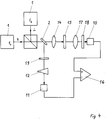
- FIG. 4 which shows the transmission mode of operation with two separate laser sources 1
- additional polarization-optical elements are used for parts of the laser beam to be separated out for the registration, which can determine the phase offset of the response signal with respect to the modulation signal of the excitation beam.
- the beam joined together by means of a beam splitter cube 13 functioning as a polarization switch reaches object 15 via the focusing lens 14 of the semitransparent mirror 2 and a polarization filter 19 a part of exactly one of the two partial beams is guided via the element with controllable transmission 12 to the reference detector 11 in order to obtain the reference signal.
- the part of the laser beam transmitted through the object 15 reaches the measuring detector 10 via the optical system 17 which is equivalent to the objective 14 and a further polarization filter 18, which is oriented in the same way as the polarization filter 19. Further processing is carried out as described in the previous three examples and allows a phase analysis in addition to the amplitude analysis.
Landscapes
- Physics & Mathematics (AREA)
- Health & Medical Sciences (AREA)
- Life Sciences & Earth Sciences (AREA)
- Chemical & Material Sciences (AREA)
- Analytical Chemistry (AREA)
- Biochemistry (AREA)
- General Health & Medical Sciences (AREA)
- General Physics & Mathematics (AREA)
- Immunology (AREA)
- Pathology (AREA)
- Investigating Or Analysing Materials By Optical Means (AREA)
- Investigating Or Analyzing Materials Using Thermal Means (AREA)
Applications Claiming Priority (2)
| Application Number | Priority Date | Filing Date | Title |
|---|---|---|---|
| DE4035266A DE4035266C2 (de) | 1990-11-02 | 1990-11-02 | Verfahren und Anordnung zur Thermowellenanalyse |
| DE4035266 | 1990-11-02 |
Publications (3)
| Publication Number | Publication Date |
|---|---|
| EP0484282A2 true EP0484282A2 (fr) | 1992-05-06 |
| EP0484282A3 EP0484282A3 (en) | 1992-07-08 |
| EP0484282B1 EP0484282B1 (fr) | 1996-04-10 |
Family
ID=6417743
Family Applications (1)
| Application Number | Title | Priority Date | Filing Date |
|---|---|---|---|
| EP91810847A Expired - Lifetime EP0484282B1 (fr) | 1990-11-02 | 1991-11-01 | Procédé et appareil d'analyse par moyen des ondes thermiques |
Country Status (4)
| Country | Link |
|---|---|
| US (1) | US5206710A (fr) |
| EP (1) | EP0484282B1 (fr) |
| AT (1) | ATE136646T1 (fr) |
| DE (1) | DE4035266C2 (fr) |
Cited By (1)
| Publication number | Priority date | Publication date | Assignee | Title |
|---|---|---|---|---|
| WO1994002834A1 (fr) * | 1992-07-16 | 1994-02-03 | Jenoptik Gmbh | Procede et installation de spectroscopie photothermique |
Families Citing this family (16)
| Publication number | Priority date | Publication date | Assignee | Title |
|---|---|---|---|---|
| US5474381A (en) * | 1993-11-30 | 1995-12-12 | Texas Instruments Incorporated | Method for real-time semiconductor wafer temperature measurement based on a surface roughness characteristic of the wafer |
| DE19511869B4 (de) * | 1995-03-31 | 2004-02-26 | Geiler, Hans-Dieter, Dr. | Verfahren und Anordnung zur Responseanalyse von Halbleitermaterialien mit optischer Anregung |
| US5861632A (en) * | 1997-08-05 | 1999-01-19 | Advanced Micro Devices, Inc. | Method for monitoring the performance of an ion implanter using reusable wafers |
| DE19747784A1 (de) * | 1997-10-29 | 1999-05-06 | Rothe Lutz Dr Ing Habil | Objekterkennung mittels Thermosignaturanalyse |
| DE19749984C2 (de) * | 1997-11-12 | 2000-05-25 | Fraunhofer Ges Forschung | Verfahren und Vorrichtungen zum photothermischen Untersuchen eines Prüfkörpers |
| DE19837889C1 (de) * | 1998-08-20 | 2000-12-21 | Siemens Ag | Thermowellen-Meßverfahren |
| WO2000020841A1 (fr) | 1998-10-05 | 2000-04-13 | Kla-Tencor Corporation | Systeme interferometrique de mesure de perturbation d'un echantillon |
| US6268916B1 (en) | 1999-05-11 | 2001-07-31 | Kla-Tencor Corporation | System for non-destructive measurement of samples |
| US6535285B1 (en) | 2000-02-08 | 2003-03-18 | Therma-Wave, Inc. | Combination thermal wave and optical spectroscopy measurement system |
| US6989899B2 (en) * | 2002-03-18 | 2006-01-24 | Therma-Wave, Inc. | Ion implant monitoring through measurement of modulated optical response |
| US7106446B2 (en) * | 2002-06-21 | 2006-09-12 | Therma-Wave, Inc. | Modulated reflectance measurement system with multiple wavelengths |
| JP4662411B2 (ja) * | 2003-03-14 | 2011-03-30 | 日立ビアメカニクス株式会社 | レーザ加工装置 |
| US7212288B2 (en) * | 2003-08-14 | 2007-05-01 | Therma-Wave, Inc. | Position modulated optical reflectance measurement system for semiconductor metrology |
| US7280215B2 (en) * | 2003-09-24 | 2007-10-09 | Therma-Wave, Inc. | Photothermal system with spectroscopic pump and probe |
| US7755752B1 (en) | 2008-04-07 | 2010-07-13 | Kla-Tencor Corporation | Combined modulated optical reflectance and photoreflectance system |
| CN103926274B (zh) * | 2014-04-22 | 2017-01-25 | 哈尔滨工业大学 | 一种cfrp层板缺陷的红外热波雷达成像无损检测方法 |
Family Cites Families (7)
| Publication number | Priority date | Publication date | Assignee | Title |
|---|---|---|---|---|
| US4044257A (en) * | 1975-02-20 | 1977-08-23 | Diax Corporation | Retention time chromatograph employing an IR absorption spectrographic detector |
| US4636088A (en) * | 1984-05-21 | 1987-01-13 | Therma-Wave, Inc. | Method and apparatus for evaluating surface conditions of a sample |
| US4579463A (en) * | 1984-05-21 | 1986-04-01 | Therma-Wave Partners | Detecting thermal waves to evaluate thermal parameters |
| US4634290A (en) * | 1984-05-21 | 1987-01-06 | Therma-Wave, Inc. | Method and apparatus for detecting thermal waves |
| FR2593917B1 (fr) * | 1986-02-06 | 1988-06-03 | Univ Reims Champagne Ardenne | Procede et dispositif d'analyse et de mesure des parametres physiques d'un materiau en couches par radiometrie thermique |
| US4795260A (en) * | 1987-05-15 | 1989-01-03 | Therma-Wave, Inc. | Apparatus for locating and testing areas of interest on a workpiece |
| US5022765A (en) * | 1987-10-23 | 1991-06-11 | International Business Machines Corporation | Nulling optical bridge for contactless measurement of changes in reflectivity and/or transmissivity |
-
1990
- 1990-11-02 DE DE4035266A patent/DE4035266C2/de not_active Expired - Lifetime
-
1991
- 1991-09-25 US US07/765,646 patent/US5206710A/en not_active Expired - Lifetime
- 1991-11-01 AT AT91810847T patent/ATE136646T1/de not_active IP Right Cessation
- 1991-11-01 EP EP91810847A patent/EP0484282B1/fr not_active Expired - Lifetime
Cited By (2)
| Publication number | Priority date | Publication date | Assignee | Title |
|---|---|---|---|---|
| WO1994002834A1 (fr) * | 1992-07-16 | 1994-02-03 | Jenoptik Gmbh | Procede et installation de spectroscopie photothermique |
| US5408327A (en) * | 1992-07-16 | 1995-04-18 | Jenoptik Gmbh | Process and arrangement for photothermal spectroscopy |
Also Published As
| Publication number | Publication date |
|---|---|
| ATE136646T1 (de) | 1996-04-15 |
| EP0484282B1 (fr) | 1996-04-10 |
| DE4035266A1 (de) | 1992-05-07 |
| US5206710A (en) | 1993-04-27 |
| DE4035266C2 (de) | 1995-11-16 |
| EP0484282A3 (en) | 1992-07-08 |
Similar Documents
| Publication | Publication Date | Title |
|---|---|---|
| EP0484282B1 (fr) | Procédé et appareil d'analyse par moyen des ondes thermiques | |
| DE4223337C2 (de) | Verfahren und Anordnung zur photothermischen Spektroskopie | |
| DE19511869B4 (de) | Verfahren und Anordnung zur Responseanalyse von Halbleitermaterialien mit optischer Anregung | |
| EP0618439B1 (fr) | Dispositif d'imagerie optique pour l'examen de milieux fortement diffusants | |
| EP0011708B1 (fr) | Méthode et dispositif pour mesurer la planéité, la rugosité ou le rayon de courbure d'une surface à mesurer | |
| DE19542490C1 (de) | Elektro-optisches Meßgerät für absolute Distanzen | |
| DE2045386C3 (de) | Gerät zur Bestimmung des CO2 -Gehaltes einer biologischen Substanz | |
| DE3029716C2 (de) | Verfahren und Vorrichtung zur automatischen Aufrechterhaltung einer Justage der Deckung und der relativen Phasenlage von Lichtstrahlen in einem für den Ultraschallempfang benutzten optischen Interferometer | |
| DE102007053632B4 (de) | Verfahren zur koaxialen Strahlanalyse an optischen Systemen | |
| EP0438465B1 (fr) | Procede et dispositif de detection quantitative de substances optiquement actives | |
| WO2017182107A1 (fr) | Procédé et dispositif de mesure de la profondeur du capillaire de vapeur pendant un processus d'usinage par faisceau à haute énergie | |
| EP0021148A1 (fr) | Procédé et dispositif de mesure interférométrique | |
| DE3322870A1 (de) | Optoakustische messvorrichtung zum bestimmen einer partikelkonzentration | |
| DE102011100252A1 (de) | Verfahren und Vorrichtung zur optischen, berührungslosen Schwingungsmessung eines schwingenden Objekts | |
| WO2013037833A1 (fr) | Procédé et dispositif de mesure de la lumière dispersée | |
| EP0443702A2 (fr) | Procédé de mesure pour déterminer de petites absorptions de lumière | |
| DE102010062842B4 (de) | Verfahren und Vorrichtung zur Bestimmung der absoluten Position eines Objekts | |
| EP2914940B1 (fr) | Procédé et dispositif pour détecter par optique laser un mouvement de surface d'un échantillon | |
| DE102005023489B4 (de) | Positionsmesseinrichtung zur Bestimmung der Position zweier entlang einer Messrichtung zueinander beweglicher Objekte und Verfahren zur Bildung eines Referenzimpulses für eine derartige Positionsmesseinrichtung | |
| DE69202780T2 (de) | Verfahren und Vorrichtung für interferometrische Absolutmessungen physikalischer Grössen. | |
| DE2453424C3 (de) | Gerät zur Analyse der Polarisationseigenschaften einer Probe | |
| EP0937229B1 (fr) | Dispositif de mesure interferometrique pour le mesurage de formes sur des surfaces rugueuses | |
| DE3542161C2 (fr) | ||
| WO2021048321A1 (fr) | Procédé et dispositif pour effectuer une spectroscopie non linéaire sur un échantillon | |
| DE2634210C2 (de) | Interferometer |
Legal Events
| Date | Code | Title | Description |
|---|---|---|---|
| PUAI | Public reference made under article 153(3) epc to a published international application that has entered the european phase |
Free format text: ORIGINAL CODE: 0009012 |
|
| AK | Designated contracting states |
Kind code of ref document: A2 Designated state(s): AT CH FR GB IT LI NL |
|
| PUAL | Search report despatched |
Free format text: ORIGINAL CODE: 0009013 |
|
| AK | Designated contracting states |
Kind code of ref document: A3 Designated state(s): AT CH FR GB IT LI NL |
|
| RAP1 | Party data changed (applicant data changed or rights of an application transferred) |
Owner name: JENOPTIK GMBH |
|
| 17P | Request for examination filed |
Effective date: 19921212 |
|
| 17Q | First examination report despatched |
Effective date: 19940518 |
|
| GRAA | (expected) grant |
Free format text: ORIGINAL CODE: 0009210 |
|
| AK | Designated contracting states |
Kind code of ref document: B1 Designated state(s): AT CH FR GB IT LI NL |
|
| REF | Corresponds to: |
Ref document number: 136646 Country of ref document: AT Date of ref document: 19960415 Kind code of ref document: T |
|
| REG | Reference to a national code |
Ref country code: CH Ref legal event code: NV Representative=s name: BOVARD AG PATENTANWAELTE |
|
| ITF | It: translation for a ep patent filed | ||
| GBT | Gb: translation of ep patent filed (gb section 77(6)(a)/1977) |
Effective date: 19960625 |
|
| ET | Fr: translation filed | ||
| GRAH | Despatch of communication of intention to grant a patent |
Free format text: ORIGINAL CODE: EPIDOS IGRA |
|
| PLBE | No opposition filed within time limit |
Free format text: ORIGINAL CODE: 0009261 |
|
| STAA | Information on the status of an ep patent application or granted ep patent |
Free format text: STATUS: NO OPPOSITION FILED WITHIN TIME LIMIT |
|
| 26N | No opposition filed | ||
| REG | Reference to a national code |
Ref country code: CH Ref legal event code: PUE Owner name: JENOPTIK GMBH TRANSFER- LEICA MICROSYSTEMS WETZLAR |
|
| REG | Reference to a national code |
Ref country code: GB Ref legal event code: 732E |
|
| REG | Reference to a national code |
Ref country code: FR Ref legal event code: TP |
|
| NLS | Nl: assignments of ep-patents |
Owner name: LEICA MICROSYSTEMS WETZLAR GMBH |
|
| NLT1 | Nl: modifications of names registered in virtue of documents presented to the patent office pursuant to art. 16 a, paragraph 1 |
Owner name: JENOPTIK AKTIENGESELLSCHAFT |
|
| REG | Reference to a national code |
Ref country code: GB Ref legal event code: IF02 |
|
| PGFP | Annual fee paid to national office [announced via postgrant information from national office to epo] |
Ref country code: CH Payment date: 20021017 Year of fee payment: 12 |
|
| PGFP | Annual fee paid to national office [announced via postgrant information from national office to epo] |
Ref country code: AT Payment date: 20021029 Year of fee payment: 12 |
|
| PG25 | Lapsed in a contracting state [announced via postgrant information from national office to epo] |
Ref country code: AT Free format text: LAPSE BECAUSE OF NON-PAYMENT OF DUE FEES Effective date: 20031101 |
|
| PG25 | Lapsed in a contracting state [announced via postgrant information from national office to epo] |
Ref country code: LI Free format text: LAPSE BECAUSE OF NON-PAYMENT OF DUE FEES Effective date: 20031130 Ref country code: CH Free format text: LAPSE BECAUSE OF NON-PAYMENT OF DUE FEES Effective date: 20031130 |
|
| REG | Reference to a national code |
Ref country code: CH Ref legal event code: PL |
|
| PG25 | Lapsed in a contracting state [announced via postgrant information from national office to epo] |
Ref country code: IT Free format text: LAPSE BECAUSE OF NON-PAYMENT OF DUE FEES;WARNING: LAPSES OF ITALIAN PATENTS WITH EFFECTIVE DATE BEFORE 2007 MAY HAVE OCCURRED AT ANY TIME BEFORE 2007. THE CORRECT EFFECTIVE DATE MAY BE DIFFERENT FROM THE ONE RECORDED. Effective date: 20051101 |
|
| NLS | Nl: assignments of ep-patents |
Owner name: DR. HANS-DIETER GEILER Effective date: 20051115 |
|
| NLT1 | Nl: modifications of names registered in virtue of documents presented to the patent office pursuant to art. 16 a, paragraph 1 |
Owner name: LEICA MICROSYSTEMS SEMICONDUCTOR GMBH |
|
| PGFP | Annual fee paid to national office [announced via postgrant information from national office to epo] |
Ref country code: NL Payment date: 20101111 Year of fee payment: 20 Ref country code: FR Payment date: 20101130 Year of fee payment: 20 |
|
| PGFP | Annual fee paid to national office [announced via postgrant information from national office to epo] |
Ref country code: GB Payment date: 20101118 Year of fee payment: 20 |
|
| REG | Reference to a national code |
Ref country code: NL Ref legal event code: V4 Effective date: 20111101 |
|
| REG | Reference to a national code |
Ref country code: GB Ref legal event code: PE20 Expiry date: 20111031 |
|
| PG25 | Lapsed in a contracting state [announced via postgrant information from national office to epo] |
Ref country code: NL Free format text: LAPSE BECAUSE OF EXPIRATION OF PROTECTION Effective date: 20111101 |
|
| PG25 | Lapsed in a contracting state [announced via postgrant information from national office to epo] |
Ref country code: GB Free format text: LAPSE BECAUSE OF EXPIRATION OF PROTECTION Effective date: 20111031 |
|
| P01 | Opt-out of the competence of the unified patent court (upc) registered |
Effective date: 20230525 |