EP0484143A2 - Servoeinrichtung für Bandantriebsrolle - Google Patents
Servoeinrichtung für Bandantriebsrolle Download PDFInfo
- Publication number
- EP0484143A2 EP0484143A2 EP91310043A EP91310043A EP0484143A2 EP 0484143 A2 EP0484143 A2 EP 0484143A2 EP 91310043 A EP91310043 A EP 91310043A EP 91310043 A EP91310043 A EP 91310043A EP 0484143 A2 EP0484143 A2 EP 0484143A2
- Authority
- EP
- European Patent Office
- Prior art keywords
- phase
- signals
- signal
- frequency
- capstan motor
- Prior art date
- Legal status (The legal status is an assumption and is not a legal conclusion. Google has not performed a legal analysis and makes no representation as to the accuracy of the status listed.)
- Granted
Links
Images



Classifications
-
- G—PHYSICS
- G11—INFORMATION STORAGE
- G11B—INFORMATION STORAGE BASED ON RELATIVE MOVEMENT BETWEEN RECORD CARRIER AND TRANSDUCER
- G11B15/00—Driving, starting or stopping record carriers of filamentary or web form; Driving both such record carriers and heads; Guiding such record carriers or containers therefor; Control thereof; Control of operating function
- G11B15/18—Driving; Starting; Stopping; Arrangements for control or regulation thereof
- G11B15/46—Controlling, regulating, or indicating speed
-
- G—PHYSICS
- G11—INFORMATION STORAGE
- G11B—INFORMATION STORAGE BASED ON RELATIVE MOVEMENT BETWEEN RECORD CARRIER AND TRANSDUCER
- G11B15/00—Driving, starting or stopping record carriers of filamentary or web form; Driving both such record carriers and heads; Guiding such record carriers or containers therefor; Control thereof; Control of operating function
- G11B15/18—Driving; Starting; Stopping; Arrangements for control or regulation thereof
- G11B15/46—Controlling, regulating, or indicating speed
- G11B15/467—Controlling, regulating, or indicating speed in arrangements for recording or reproducing wherein both record carriers and heads are driven
- G11B15/4673—Controlling, regulating, or indicating speed in arrangements for recording or reproducing wherein both record carriers and heads are driven by controlling the speed of the tape while the head is rotating
- G11B15/4675—Controlling, regulating, or indicating speed in arrangements for recording or reproducing wherein both record carriers and heads are driven by controlling the speed of the tape while the head is rotating with provision for information tracking
-
- G—PHYSICS
- G11—INFORMATION STORAGE
- G11B—INFORMATION STORAGE BASED ON RELATIVE MOVEMENT BETWEEN RECORD CARRIER AND TRANSDUCER
- G11B15/00—Driving, starting or stopping record carriers of filamentary or web form; Driving both such record carriers and heads; Guiding such record carriers or containers therefor; Control thereof; Control of operating function
- G11B15/18—Driving; Starting; Stopping; Arrangements for control or regulation thereof
- G11B15/1808—Driving of both record carrier and head
- G11B15/1875—Driving of both record carrier and head adaptations for special effects or editing
-
- G—PHYSICS
- G11—INFORMATION STORAGE
- G11B—INFORMATION STORAGE BASED ON RELATIVE MOVEMENT BETWEEN RECORD CARRIER AND TRANSDUCER
- G11B15/00—Driving, starting or stopping record carriers of filamentary or web form; Driving both such record carriers and heads; Guiding such record carriers or containers therefor; Control thereof; Control of operating function
- G11B15/18—Driving; Starting; Stopping; Arrangements for control or regulation thereof
- G11B15/46—Controlling, regulating, or indicating speed
- G11B15/467—Controlling, regulating, or indicating speed in arrangements for recording or reproducing wherein both record carriers and heads are driven
-
- H—ELECTRICITY
- H02—GENERATION; CONVERSION OR DISTRIBUTION OF ELECTRIC POWER
- H02P—CONTROL OR REGULATION OF ELECTRIC MOTORS, ELECTRIC GENERATORS OR DYNAMO-ELECTRIC CONVERTERS; CONTROLLING TRANSFORMERS, REACTORS OR CHOKE COILS
- H02P23/00—Arrangements or methods for the control of AC motors characterised by a control method other than vector control
- H02P23/18—Controlling the angular speed together with angular position or phase
- H02P23/186—Controlling the angular speed together with angular position or phase of one shaft by controlling the prime mover
Definitions
- This invention relates to capstan servo devices, for use, for example, in a video tape recorder (VTR).
- VTR video tape recorder
- FIG 8 is a block diagram of a previously proposed capstan servo device which includes a capstan motor 1, a frequency generator (FG) 2 for generating a frequency signal proportional to the rotation speed of the capstan motor 1, a speed detector 83 for detecting a speed error e v by frequency-discriminating the FG signal, a phase compensator 85, a mixer 86, and a driver 10. These component elements form a speed loop for controlling the rotation speed of the capstan motor 1 to maintain it constant.
- FG frequency generator
- Another group of component elements comprising a frequency divider 87, and a phase detector 84 for detecting a phase error e p between the demultiplied output signal of the frequency divider 87 and a reference signal V-SYNC, and for supplying such phase error e p to the mixer 86, form a phase loop for controlling the rotation phase of the capstan motor 1 and maintaining it constant.
- the motion of a magnetic tape 82 is maintained at a constant speed by the two control loops.
- a recording mode where a switch circuit 88 is connected to a recording (R) side, the capstan motor 1 is rotated in synchronism with the rotation phase of the signal V-SYNC.
- the switch circuit 88 is connected to a playback (P) side, the capstan motor 1 is so rotated that a CTL signal, which is read out by a control head 81 from a control track (not shown) on the tape 82 and serves as a comparison signal, is synchronized in phase with the signal V-SYNC.
- Recent capstan servo devices provide, in addition to a recording/playback mode executed with constant-speed rotation of a capstan motor, other operational modes, such as a mode to reproduce a still picture by controlling the stop position of a magnetic tape by control of the rotation and stopping of the capstan motor, and a mode to perform changed-speed playback by controlling the capstan motor continuously from slow rotation to fast rotation. Such modes call for further precise control.
- a capstan motor 1 is rotated at a normal constant speed under control of a known speed-phase servo circuit 91.
- a signal F a+ of Figure 10A produced from an FG signal f a is supplied as a stop signal to a driver 10.
- the capstan motor 1 is so controlled as to stop when the voltage applied to the driver 10 is reduced to zero, and the rotation speed is accelerated by a positive voltage increased from the zero point or is decelerated by a negative voltage decreased therefrom. Accordingly, of zero crossing points P and Q in each of right slope portions and left slope portions as shown in Figure 10A, a stable point for stop control is the point P, and with any point Q, and desired stability is achieved with a shift to either the anterior or posterior point P.
- the FG 2 generates two-phase signals f a and f b having a 90° phase difference.
- Such two-phase signals f a and f b are supplied respectively to non-inverting amplifiers 3a and 3b and inverting amplifiers 4a and 4b of a stop control circuit 92 to become four-phase signals F a+ , F a- and F b+ , F b ⁇ shown in Figures 10A to 10D.
- the two-phase signals f a and f b are also supplied to comparators 93a and 93b to be converted into pulses at the average-level zero crossing points, whereby rectangular signals S a and S b of Figures 10E and 10F are obtained.
- the four-phase signals F a+ , F a- and F b+ , F b- are supplied to switch circuits 94a and 94b respectively, and are thereby switched in accordance with the rectangular pulses S a and S b , so that the right slope portions alone are extracted to produce signals D a and D b of waveforms shown in Figures 10G and 10H.
- signals D a and D b are mixed with each other in a mixer 95 to become a signal D s of Figure 10J, where the zero crossing points in the former four-phase waveforms are in the right slope portions alone.
- a capstan servo device comprising: a frequency generator for detecting the rotation speed of a capstan motor and generating two-phase FG signals having a mutual 90° phase difference; a selector for selecting one of input four-phase signals having a mutual 90° phase difference, said four-phase signals being obtained by inverting and not inverting said two-phase FG signals and amplifying the same; and a sync signal generator including an N-bit counter (where N ⁇ 2) to receive a reference frequency signal inputted thereto and generating a sync signal by phase-comparing the two high-order bits of the frequency-divided output of said counter with said two-phase FG signals; wherein the rotation speed of said capstan motor is controlled in accordance with an error voltage signal selected by said selector in response to the sync signal.
- a capstan servo device comprising: a frequency generator for detecting the rotation speed of a capstan motor and generating two-phase FG signals having a mutual 90° phase difference; a selector for selecting one of input four-phase signals having a mutual 90° phase difference, said four-phase signals being obtained by inverting and not inverting said two-phase FG signals and amplifying the same; a sync signal generator including an N-bit counter (where N ⁇ 2) to receive a reference frequency signal inputted thereto and generating a sync signal by phase-comparing the two high-order bits of the frequency-divided output of said counter with said two-phase FG signals; and a digital-to-analogue converter for converting the (N - 2) low-order bits of the frequency-divided output of said counter into an analogue form; wherein the rotation speed of said capstan motor is controlled in accordance with a difference voltage between the output voltage of said converter and the error voltage signal selected by said selector in response to
- a capstan servo device comprising: a frequency generator for detecting the rotation speed of a capstan motor and generating two-phase FG signals having a mutual 90° phase difference; a selector for selecting one of input four-phase signals having a mutual 90° phase difference, said four-phase signals being obtained by inverting and not inverting said two-phase FG signals and amplifying the same; a phase locked loop for generating a reference frequency signal while being phase-locked to an internal reference signal during a recording mode or to a control signal during a playback mode; and a sync signal generator including an N-bit counter (where N ⁇ 2) to receive a reference frequency signal inputted thereto and generating a sync signal by phase-comparing the two high-order bits of the frequency-divided output of said counter with said two-phase FG signals; wherein the rotation speed and the rotation phase of said capstan motor is controlled in accordance with an error voltage signal selected by said selector in response to the sync signal.
- Speed control is executed by closed-loop phase servo in embodiments of the invention, so that the capstan motor is continuously controllable with a smooth action from stop through slow rotation to fast rotation.
- phase loop Since the phase loop is connected in series to the speed loop, optimum values are settable in each of the loops with regard to the stability and the pull-in time for synchronization.
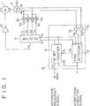
- the embodiment of Figure 1 comprises a selector 5 for selecting one of four inputs in response to a 2-bit control signal, and outputting the selected input.
- a sync signal generator 6 comprises pulse shapers 7a and 7b, an N-bit counter 8 and a sync detector 9.
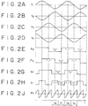
- the FG signals f a and f b are also fed to the sync signal generator 6 and are processed by the pulse shapers 7a and 7b to become digital signals F a and F b as shown in Figures 2E and 2F.
- a reference frequency signal f R serving as a reference for the rotation rate of the capstan motor 1 is supplied to a clock input terminal CK of the N-bit counter 8 in the sync signal generator 6 so as to be frequency-divided or demultiplied by N.
- the waveforms of Figures 2G and 2H represent the two high-order bits S0 and S1 in the N bits of the demultiplied output of the counter 8.
- Such output bits S0 and S1 are supplied to the sync detector 9 to be compared with the digitized FG signals F a and F b , and the input CL of the counter 8 is controlled by an output C0 obtained as a result of such comparison.
- the FG signals are synchronized with the reference frequency signal, and the demultiplied outputs S0 and S1 are fed as sync signals to the selector 5.
- a rotational frequency signal indicating the forward or backward rotation of the capstan motor 1 is supplied to the U/D input terminal of the counter 8 and also to the sync detector 9.
- the waveform timing chart of Figure 2 illustrates the phase relation among the signals in the synchronized state of the capstan servo device.
- a signal f1 is selected during a time period T1 where the bits of the sync signals S0 and S1 are combined as (0, 0); a signal f4 is selected during a time period T4 where the bits are (0, 1); a signal f2 is selected during a time period T2 where the bits are (1, 0); and a signal f3 is selected during a time period T3 where the bits are (1, 1).
- a signal D0 of the waveform shown in Figure 2J which is composed merely of the left slope portions having a 1 ⁇ 4 period of the original FG signal.
- the error voltage signal e0 of such waveform is supplied to the driver 10 thereby to form a closed loop for controlling the capstan motor 1 at a predetermined rotation rate.
- the synchronization can be performed by first detecting such a lag or lead by the sync detector 9 and then presetting, in accordance with the detected lag or lead, the clock input of the counter 8 forcibly to the values of (S0, S1) suited for synchronizing with the states of (F a , F b ). More specifically, there occurs a lag during the time period T1 when (F a , F b ) are (0, 1), in the case where (S0, S1) are (0, 0).
- This diagram signifies that synchronization can be achieved by outputting a preset control signal C0 to the state values of (S0, S1) within the ellipse at the head of the arrow.
- a control signal C0 for presetting the counter 8 is outputted in accordance with the state transition diagram, and sync signals S0, S1 are generated through synchronization with the input FG signals F a , F b thereby to control the selector 5.
- the operation mentioned above is repeated cyclically to synchronize the servo loop, thereby placing the same in the locked state of Figure 2.
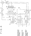
- the second embodiment shown in Figure 4, includes, in addition to the aforementioned constitution of Figure 1, a D/A converter 41 for extracting the low-order bits from a counter in a sync signal generator 6 and executing digital-to-analogue conversion of the extracted signal, and a differential amplifier 42 for producing the difference between the output e1 of the D/A converter 41 and the output e0 of a selector 5.
- a D/A converter 41 for extracting the low-order bits from a counter in a sync signal generator 6 and executing digital-to-analogue conversion of the extracted signal
- a differential amplifier 42 for producing the difference between the output e1 of the D/A converter 41 and the output e0 of a selector 5.
- FIG. 5A and 5B denote sync signals S0 and S1 corresponding to Figures 2G and 2B respectively, and Figure 5E denotes an error voltage signal e0 corresponding to Figure 2J.
- N 4 in the counter 8
- low-order bits S2 and S3 of Figures 5C and 5D can be extracted as demultiplied outputs.
- Such outputs S2 and S3 are fed to the D/A converter 41, which then produces an analogue output e1 of Figure 5F.
- This output e1 is supplied to the differential amplifier 42, where the difference between such output e1 and the output e0 of the selector 5 is produced as a differential output e c .
- the lower frequency component has been removed from the output e0 of the selector 5, and the voltage ripple has been reduced to 1 ⁇ 2 N-2 . Therefore, when slow rotation control is executed for the capstan motor 1 in the first embodiment by lowering the frequency of the reference frequency signal f R , the problem of electromagnetic noise generated by the ripple current from the capstan motor 1 can be improved if the error voltage output e0 of the selector 5 is reduced into a range of 100 Hz to several kHz.
- the following is an exemplary case of rotating the capstan motor 1 at a high speed by raising the reference frequency signal f R .
- the frequency range of the signal f R is so widened as to cover from 0 to f S ⁇ 2 N Hz. If the frequency f S of the FG signal generated at the standard rotation of the capstan motor 1 is set to 500 Hz, the reference frequency signal f R comes to have a frequency of 32 kHz with N of the counter 8 being six bits.
- the frequency becomes 320 kHz at a 10-fold speed, and 1.6 MHz at a 50-fold speed.
- Figure 6 graphically shows the relationship between the FG frequency f S and the reference frequency signal f R under control at changed speeds.
- FIG. 7 is a block diagram of the third embodiment which comprises a speed servo circuit 71 contrived by modifying the capstan servo device described already in connection with the first embodiment, wherein some internal circuits in Figure 1 are eliminated inclusive of the FG signal input from the FG 2 and the circuit from the reference frequency signal input to the driving output for the capstan motor 1. Further shown components include a reference frequency generator 72, a switch circuit (A) 73, a switch circuit (B) 79, and a phase locked loop (PLL) circuit 74 comprising a phase detector 75, a phase compensator 76, a voltage controlled oscillator (VCO) 77, and a frequency divider 78.
- PLL phase locked loop
- phase loop described with regard to the capstan servo device of Figure 8 is additionally incorporated in the first embodiment of the present invention shown in Figure 1, and the speed loop and the phase loop are connected in series to each other.
- the switch circuit (A) 73 is selectively connected to its N side.
- a continuous frequency signal f p phase-locked to either an internal reference signal or a signal V-SYNC is generated from the PLL circuit 74 and is then supplied as a reference frequency signal to the speed servo circuit 7.
- the switch circuit (B) 79 is changed to its P side to be connected to the control head 81.
- a phase servo is achieved for rotating the capstan motor 1 in such a manner that, during the recording operation, the rotation phase of the capstan motor 1 is synchronized with the internal reference signal similarly to the phase loop employed in the capstan servo device of Figure 8; and during the playback operation, the CTL signal read out by the control head 81 from a control track (not shown) on the tape 82 is synchronized with the phase of the signal V-SYNC.
- the switch circuit (A) 73 to its V side, the aforementioned phase loop is disconnected from the above state and is then connected to the reference frequency generator 72, so that the speed loop alone functions to execute speed control in accordance with the reference frequency. Since this control is the same as the one described in detail with regard to the first and second embodiments, a repeated explanation is omitted here.
- the present invention is not limited merely to the above embodiments representing exemplary cases of speed control for the capstan motor, and it may also be applied to speed control for a linear motor (VCM) or the like.
- VCM linear motor
- the speed loop for the capstan motor is controlled by the phase servo alone based on the FG signal, so that any loop characteristic variation derived from the rotation speed of the capstan motor can be eliminated consequently to achieve wide range control covering from a stop to fast rotation.
- the speed loop and the phase loop are connected in series to each other, any torque disturbance from the capstan motor can be absorbed by the speed loop to attain a great improvement in elimination of rotational variations.
- the phase loop serves to control merely the phase relation between the signal V-SYNC and the signal CTL without functioning directly as a loop for control of the capstan motor, so that the loop gain need not be raised beyond the necessity eventually to realize adequate setting for attaining required stability.
- capstan servo device in a VTR, it is possible to enhance the stop position accuracy of a magnetic tape relative to a rotary magnetic head as well as to realize a continuously changeable motion of the magnetic tape, hence obtaining superior still picture quality and a special playback function for smooth and continuous speed changes covering from slow playback to fast playback.
Landscapes
- Engineering & Computer Science (AREA)
- Signal Processing (AREA)
- Power Engineering (AREA)
- Control Of Electric Motors In General (AREA)
Applications Claiming Priority (2)
| Application Number | Priority Date | Filing Date | Title |
|---|---|---|---|
| JP2292132A JP3021606B2 (ja) | 1990-10-31 | 1990-10-31 | キャプスタンサーボ装置 |
| JP292132/90 | 1990-10-31 |
Publications (3)
| Publication Number | Publication Date |
|---|---|
| EP0484143A2 true EP0484143A2 (de) | 1992-05-06 |
| EP0484143A3 EP0484143A3 (en) | 1993-01-13 |
| EP0484143B1 EP0484143B1 (de) | 1996-09-04 |
Family
ID=17777952
Family Applications (1)
| Application Number | Title | Priority Date | Filing Date |
|---|---|---|---|
| EP91310043A Expired - Lifetime EP0484143B1 (de) | 1990-10-31 | 1991-10-30 | Servoeinrichtung für Bandantriebsrolle |
Country Status (5)
| Country | Link |
|---|---|
| US (1) | US5144210A (de) |
| EP (1) | EP0484143B1 (de) |
| JP (1) | JP3021606B2 (de) |
| KR (1) | KR100255733B1 (de) |
| DE (1) | DE69121839T2 (de) |
Families Citing this family (7)
| Publication number | Priority date | Publication date | Assignee | Title |
|---|---|---|---|---|
| US5452144A (en) * | 1992-09-17 | 1995-09-19 | Sanyo Electric Co., Ltd. | Video tape recorder carrying out field extraction recording and/or reproduction of a video signal |
| US5467004A (en) * | 1992-11-24 | 1995-11-14 | Matsushita Electric Industrial Co., Ltd. | Motor speed control apparatus for keeping the speed of the motor fixed in the presence of a disturbance torque |
| JP3270908B2 (ja) * | 1993-04-16 | 2002-04-02 | ソニー株式会社 | モータ制御装置及び方法 |
| US5589746A (en) * | 1994-11-10 | 1996-12-31 | Seagate Technology, Inc. | Brushless motor speed control arrangement having derived common mode supply signal component |
| KR0147344B1 (ko) * | 1995-01-28 | 1998-10-15 | 구자홍 | 브이씨알의 캡스턴 위상 제어 방법 |
| WO2007110729A2 (en) * | 2006-03-24 | 2007-10-04 | Herman Miller Inc. | Seating arrangement |
| KR102452137B1 (ko) | 2020-09-22 | 2022-10-11 | 주식회사 한국인삼공사 | 떠짐성이 개선된 형상 기억 화장료 조성물 및 이의 제조방법 |
Family Cites Families (10)
| Publication number | Priority date | Publication date | Assignee | Title |
|---|---|---|---|---|
| US3492441A (en) * | 1967-07-03 | 1970-01-27 | Ball Brothers Res Corp | Bandwidth reduction system for a magnetic recorder |
| JPS5344777A (en) * | 1976-10-03 | 1978-04-21 | Ricoh Co Ltd | Closed loop servo-controlling system |
| JPS573589A (en) * | 1980-06-06 | 1982-01-09 | Sony Corp | Controlling circuit for stopping of dc motor |
| JPS5783978A (en) * | 1980-11-12 | 1982-05-26 | Sony Corp | Video signal recorder and reproducer |
| AU570922B2 (en) * | 1982-06-30 | 1988-03-31 | Sony Corporation | Digital servo circuit for motor control |
| JPH0754571B2 (ja) * | 1983-02-02 | 1995-06-07 | キヤノン株式会社 | ビデオ信号再生装置 |
| US4630146A (en) * | 1984-03-13 | 1986-12-16 | Canon Kabushiki Kaisha | Rotary head type reproducing apparatus |
| JPS6126955A (ja) * | 1984-07-17 | 1986-02-06 | Hitachi Ltd | 磁気記録再生装置のオ−トトラツキング装置 |
| JPH0528589Y2 (de) * | 1985-10-15 | 1993-07-22 | ||
| DE3718207A1 (de) * | 1987-05-29 | 1988-12-15 | Thomson Brandt Gmbh | Verfahren zur steuerung der drehzahl eines rotors |
-
1990
- 1990-10-31 JP JP2292132A patent/JP3021606B2/ja not_active Expired - Fee Related
-
1991
- 1991-10-28 US US07/783,257 patent/US5144210A/en not_active Expired - Fee Related
- 1991-10-30 DE DE69121839T patent/DE69121839T2/de not_active Expired - Fee Related
- 1991-10-30 EP EP91310043A patent/EP0484143B1/de not_active Expired - Lifetime
- 1991-10-31 KR KR1019910019236A patent/KR100255733B1/ko not_active Expired - Fee Related
Also Published As
| Publication number | Publication date |
|---|---|
| EP0484143A3 (en) | 1993-01-13 |
| KR100255733B1 (ko) | 2000-05-01 |
| US5144210A (en) | 1992-09-01 |
| EP0484143B1 (de) | 1996-09-04 |
| DE69121839T2 (de) | 1997-02-13 |
| JP3021606B2 (ja) | 2000-03-15 |
| KR920008698A (ko) | 1992-05-28 |
| JPH04168989A (ja) | 1992-06-17 |
| DE69121839D1 (de) | 1996-10-10 |
Similar Documents
| Publication | Publication Date | Title |
|---|---|---|
| JPS6146849B2 (de) | ||
| US4047231A (en) | High stability digital head servo for video recorders | |
| US4459612A (en) | Vertical synchronizing signal detecting circuit | |
| GB2042223A (en) | Motor speed control circuits | |
| EP0484143B1 (de) | Servoeinrichtung für Bandantriebsrolle | |
| KR100213959B1 (ko) | 회전체의 위상 및 속도 제어용 마이크로 컴퓨터 사용 디지탈 서보시스템 | |
| EP0266147B1 (de) | Phasenregelschleifenschaltung für ein Fernsehgerät | |
| EP0116926B1 (de) | Gerät zur magnetischen Aufzeichnung und Wiedergabe | |
| US4562394A (en) | Motor servo circuit for a magnetic recording and reproducing apparatus | |
| HK1002618B (en) | A phase-lock-loop circuit for a television apparatus | |
| US4780774A (en) | Rotary head type reproducing apparatus having a head shifter for accurately shifting the rotary head | |
| US4670694A (en) | Capstan motor control circuit | |
| JPS60126988A (ja) | 編集用記録再生装置におけるカラ−フレ−ムサ−ボ回路 | |
| JPH0638716B2 (ja) | 回転体の制御装置 | |
| KR900008445Y1 (ko) | 브이. 티. 알의 ntsc/pal겸용 서보 제어회로 | |
| JP2748746B2 (ja) | 位相同期発振器 | |
| KR100207633B1 (ko) | 위상동기루프회로 | |
| JPS6235155Y2 (de) | ||
| JPH057830Y2 (de) | ||
| CA1097801A (en) | Digital phase servo system | |
| JPS6020188Y2 (ja) | キヤプスタンサ−ボ回路 | |
| JPH0570216B2 (de) | ||
| JPH0410134B2 (de) | ||
| JPS60229264A (ja) | 磁気記録再生装置の可変速サ−ボ装置 | |
| JPH0752540B2 (ja) | デイジタル位相制御装置 |
Legal Events
| Date | Code | Title | Description |
|---|---|---|---|
| PUAI | Public reference made under article 153(3) epc to a published international application that has entered the european phase |
Free format text: ORIGINAL CODE: 0009012 |
|
| AK | Designated contracting states |
Kind code of ref document: A2 Designated state(s): DE FR GB |
|
| PUAL | Search report despatched |
Free format text: ORIGINAL CODE: 0009013 |
|
| AK | Designated contracting states |
Kind code of ref document: A3 Designated state(s): DE FR GB |
|
| 17P | Request for examination filed |
Effective date: 19930529 |
|
| 17Q | First examination report despatched |
Effective date: 19950803 |
|
| GRAH | Despatch of communication of intention to grant a patent |
Free format text: ORIGINAL CODE: EPIDOS IGRA |
|
| GRAH | Despatch of communication of intention to grant a patent |
Free format text: ORIGINAL CODE: EPIDOS IGRA |
|
| GRAA | (expected) grant |
Free format text: ORIGINAL CODE: 0009210 |
|
| AK | Designated contracting states |
Kind code of ref document: B1 Designated state(s): DE FR GB |
|
| REF | Corresponds to: |
Ref document number: 69121839 Country of ref document: DE Date of ref document: 19961010 |
|
| ET | Fr: translation filed | ||
| PLBE | No opposition filed within time limit |
Free format text: ORIGINAL CODE: 0009261 |
|
| STAA | Information on the status of an ep patent application or granted ep patent |
Free format text: STATUS: NO OPPOSITION FILED WITHIN TIME LIMIT |
|
| 26N | No opposition filed | ||
| REG | Reference to a national code |
Ref country code: GB Ref legal event code: IF02 |
|
| PGFP | Annual fee paid to national office [announced via postgrant information from national office to epo] |
Ref country code: FR Payment date: 20031003 Year of fee payment: 13 |
|
| PGFP | Annual fee paid to national office [announced via postgrant information from national office to epo] |
Ref country code: GB Payment date: 20031029 Year of fee payment: 13 |
|
| PGFP | Annual fee paid to national office [announced via postgrant information from national office to epo] |
Ref country code: DE Payment date: 20031103 Year of fee payment: 13 |
|
| PG25 | Lapsed in a contracting state [announced via postgrant information from national office to epo] |
Ref country code: GB Free format text: LAPSE BECAUSE OF NON-PAYMENT OF DUE FEES Effective date: 20041030 |
|
| PG25 | Lapsed in a contracting state [announced via postgrant information from national office to epo] |
Ref country code: DE Free format text: LAPSE BECAUSE OF NON-PAYMENT OF DUE FEES Effective date: 20050503 |
|
| GBPC | Gb: european patent ceased through non-payment of renewal fee |
Effective date: 20041030 |
|
| PG25 | Lapsed in a contracting state [announced via postgrant information from national office to epo] |
Ref country code: FR Free format text: LAPSE BECAUSE OF NON-PAYMENT OF DUE FEES Effective date: 20050630 |
|
| REG | Reference to a national code |
Ref country code: FR Ref legal event code: ST |