EP0483607B1 - Procédé pour identifier la qualité d'un matériau fibreux - Google Patents
Procédé pour identifier la qualité d'un matériau fibreux Download PDFInfo
- Publication number
- EP0483607B1 EP0483607B1 EP91117712A EP91117712A EP0483607B1 EP 0483607 B1 EP0483607 B1 EP 0483607B1 EP 91117712 A EP91117712 A EP 91117712A EP 91117712 A EP91117712 A EP 91117712A EP 0483607 B1 EP0483607 B1 EP 0483607B1
- Authority
- EP
- European Patent Office
- Prior art keywords
- measuring
- sliver
- fibre bundle
- mixture
- measurement
- Prior art date
- Legal status (The legal status is an assumption and is not a legal conclusion. Google has not performed a legal analysis and makes no representation as to the accuracy of the status listed.)
- Expired - Lifetime
Links
- 238000000034 method Methods 0.000 title claims description 51
- 239000002657 fibrous material Substances 0.000 title description 7
- 239000000835 fiber Substances 0.000 claims description 47
- 238000005259 measurement Methods 0.000 claims description 37
- 239000000203 mixture Substances 0.000 claims description 21
- 239000000523 sample Substances 0.000 claims description 9
- 229920002994 synthetic fiber Polymers 0.000 claims description 8
- 239000000463 material Substances 0.000 claims description 7
- 238000002156 mixing Methods 0.000 claims description 4
- 238000003825 pressing Methods 0.000 claims description 3
- 230000001771 impaired effect Effects 0.000 claims description 2
- 238000001228 spectrum Methods 0.000 claims description 2
- 230000007423 decrease Effects 0.000 claims 1
- 238000011156 evaluation Methods 0.000 claims 1
- 238000005286 illumination Methods 0.000 claims 1
- 230000006835 compression Effects 0.000 description 13
- 238000007906 compression Methods 0.000 description 13
- 238000003860 storage Methods 0.000 description 8
- 239000012209 synthetic fiber Substances 0.000 description 5
- 238000004140 cleaning Methods 0.000 description 4
- 238000000151 deposition Methods 0.000 description 4
- 239000004753 textile Substances 0.000 description 4
- 229920000742 Cotton Polymers 0.000 description 3
- 230000001105 regulatory effect Effects 0.000 description 3
- 230000000694 effects Effects 0.000 description 2
- 239000011521 glass Substances 0.000 description 2
- 230000007774 longterm Effects 0.000 description 2
- 230000003287 optical effect Effects 0.000 description 2
- 238000012545 processing Methods 0.000 description 2
- 230000015572 biosynthetic process Effects 0.000 description 1
- 239000007795 chemical reaction product Substances 0.000 description 1
- 239000003795 chemical substances by application Substances 0.000 description 1
- 230000001143 conditioned effect Effects 0.000 description 1
- 230000008021 deposition Effects 0.000 description 1
- 238000013461 design Methods 0.000 description 1
- 238000001514 detection method Methods 0.000 description 1
- 239000000428 dust Substances 0.000 description 1
- 230000002349 favourable effect Effects 0.000 description 1
- 238000009499 grossing Methods 0.000 description 1
- 238000003384 imaging method Methods 0.000 description 1
- 239000013067 intermediate product Substances 0.000 description 1
- 230000004807 localization Effects 0.000 description 1
- 239000000047 product Substances 0.000 description 1
- 238000005204 segregation Methods 0.000 description 1
- 239000000126 substance Substances 0.000 description 1
- 238000012360 testing method Methods 0.000 description 1
- 239000012780 transparent material Substances 0.000 description 1
- 238000011144 upstream manufacturing Methods 0.000 description 1
Images
Classifications
-
- D—TEXTILES; PAPER
- D01—NATURAL OR MAN-MADE THREADS OR FIBRES; SPINNING
- D01G—PRELIMINARY TREATMENT OF FIBRES, e.g. FOR SPINNING
- D01G31/00—Warning or safety devices, e.g. automatic fault detectors, stop motions
- D01G31/006—On-line measurement and recording of process and product parameters
-
- D—TEXTILES; PAPER
- D01—NATURAL OR MAN-MADE THREADS OR FIBRES; SPINNING
- D01G—PRELIMINARY TREATMENT OF FIBRES, e.g. FOR SPINNING
- D01G13/00—Mixing, e.g. blending, fibres; Mixing non-fibrous materials with fibres
-
- G—PHYSICS
- G01—MEASURING; TESTING
- G01N—INVESTIGATING OR ANALYSING MATERIALS BY DETERMINING THEIR CHEMICAL OR PHYSICAL PROPERTIES
- G01N33/00—Investigating or analysing materials by specific methods not covered by groups G01N1/00 - G01N31/00
- G01N33/36—Textiles
- G01N33/365—Filiform textiles, e.g. yarns
Definitions
- each provenance has predetermined fiber properties and in which each provenance is a mixed component of a predetermined percentage, and in which the mixture as a whole has predetermined fiber properties and the mixing components are controllable variable components at all times.
- the percentage of each component in order to achieve the fiber properties of the mixture mentioned is automatically optimized, taking into account the fiber properties of the individual components, by the component mixture depending on predetermined and determined properties of a subsequently produced intermediate product, preferably a card sliver or a subsequently produced end product , preferably a yarn, are determined and corrected immediately and automatically in the event of deviations therefrom.
- the process of the European patent application mentioned shows and describes the possibility of transferring the textile fibers of different provenance either directly from the fiber bales or from component cells to a mixer in which these components are mixed homogeneously.
- the product of the mixer is then cleaned in a blow room and then handed over for processing a card.
- the card sliver is checked in a color testing device and the corresponding signal is sent to a controller that controls the component mixture.
- provenance can be understood to mean cotton fiber bales or fiber bales with synthetic fibers, so that the mixture can be mixtures of different types of cotton or a mixture of cotton fibers and man-made fibers.
- US-A-4,758,968 describes a method and an apparatus for the continuous measurement of changes in textile fiber slivers. For this purpose, the changes of one or more parameters of the textile fiber sliver should be measured. It can be seen from the first exemplary embodiments that the signal from a signal converter which has at least one parameter, e.g. the linear fiber density, monitored, is processed in three different signal-integrating and signal-smoothing circuits with a different time constant. Long-term errors in a range of wavelength bands can be extracted from this.
- the further exemplary embodiments (FIGS. 9 to 12) furthermore show that a plurality of signal converters can also be used to observe the long-term changes in a parameter. However, these measurements cannot be used to determine the proportions of the mixture in a fiber structure.
- a process point at which the fiber structure is deposited in overlapping layers can be selected as the measuring point.
- the advantage of the invention is that the mixture of natural and artificial fibers can be determined in a relatively simple manner in an earlier stage of the fiber processing process with sufficiently high accuracy, which is particularly advantageous because the artificial fibers usually have a significantly different price than the natural fibers and therefore exact compliance with the synthetic fiber content is required by law in different countries.
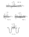
- a measuring probe 1 shows a measuring probe 1, which is arranged perpendicular to the running direction B of a fiber structure or also a fiber band and the band surface is guided past it at a constant distance from it.
- the measurement could also be carried out on a stationary fiber structure.
- the sliver is slightly compressed by compression means 2 before it passes through the measuring point.
- the measurement is made through an appropriately transparent device part 3 (plane glass pane) or through a small opening (without plane glass pane) between the compression means.
- Appropriate design of the compression means be it process-related or purely measurement-related, ensures that the tape at the measuring point has a sufficient width to cover the entire measuring opening of the measuring probe.
- the above concentration is measured by evaluating spectra in the near infrared range using an FT-NIR spectrometer from Buhler, CH-9240 Uzwil.
- variant 1 Three process variants are available for compressing the sliver in the area of the measuring point.
- the measurement is carried out at a process point at which the sliver is compressed due to the process, i.e. where the compression means 2b, e.g. a funnel represents a process-specific device part.
- the compression means 2b e.g. a funnel represents a process-specific device part.
- the measurement is carried out at any process point, and the sliver is compressed in the area of the measuring point without braking, between compression means 2c running with the band.
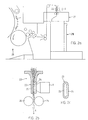
- FIG. 2 shows an exemplary embodiment of the measuring device according to the invention.
- Process-related compression in a funnel is used for the compression of the fiber sliver, so method variant 1 (FIG. 1b) is used.
- FIG. 2a it can be the funnel of a tape depositing device, such as those used for tape depositing in cans.
- it can also be the feed hopper for a pair of stepped rollers or a measuring hopper that is installed for measuring the strip density.
- FIG. 2a shows, as an example of a localization of the device according to the invention, schematically the exit of the fiber sliver from a card 20 and its feeding to a card Tape deposit device 21 on a can 211.
- the measuring probe 1 is installed on the hopper 22 of the tape deposit device.
- the funnel 22 is specially designed for this purpose.
- the funnel neck 23 is designed as a measuring cuvette. So that the continuous band has a width sufficient for the measurement, the funnel neck 23 has the cross section shown in FIG. 2c with the shape of a very flat rectangle with rounded corners.
- the wide side 24 of the funnel neck 23 facing the measuring probe consists of a transparent material.
- a few transport rollers 26 follow the storage hopper in the direction of the wall.
- FIG. 2d shows the control of the loop formation based on FIG. 1d, which is described, for example, in DE-B-1931929 and in this form likewise requires the can filling to be started and stopped at Measurement.
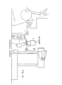
- FIG. 3 shows a side view (FIG. 3a) and a top view (FIG. 3b) of an exemplary embodiment of the device according to the invention, which is suitable for carrying out the method according to the invention, and in which the continuous sliver according to process variant II (FIG. 1c ) is compressed specifically for the measurement.
- the device can be used at any process point where a sliver is freely transported over a sufficiently long distance. Since the sliver must not be slowed down by the compression, it must be actively transported through the measuring section.
- the sliver is transported, for example, by endless belts 30, 31 and 32, the belts 30 and 31 being aligned in a straight line, with a transparent plate 34 lying between them on one side, the belt 32 on the other side of the
- the sliver is arranged in such a way that a narrowed measuring section is formed between the transparent plate 34 and the belt 32.
- the belt 32 thus also acts as a compression means.
- the measuring probe 1 is positioned on the side of the transparent plate facing away from the sliver.
- the plate 43 is the only part that comes into contact with the continuous belt, stationary. However, since the belt is transported through the belts on both sides of the plate, the braking effect is negligible.
- the transparent plate 34 can also be omitted and the measurement can be carried out through a corresponding gap between the belts 30 and 31.
- the two belts 30 and 31 are driven by the drive rollers 35.1 and 35.2 and are guided adjacent to the transparent plate 34 around two plate-shaped links 36.1 and 36.2.
- By using such plate-shaped backdrops it is possible, on the one hand, to guide the belts up to the transparent plate 34 in the same plane in which the plate 34 lies, and, on the other hand, there is space on the side of the plate 34 facing away from the continuous sliver to be sufficiently close to the measuring probe to position on the plate 34.
- Similar belt drives are e.g. known from DE-A-3327966, which describes the use of such belt drives in a drafting system.
- the belt 32 is driven by two drive rollers 37.1 and 37.2 and guided over two trailed rollers 38.1 and 38.2.
- the distance between the rollers 37 and the belts 30 and 31 corresponds approximately to the thickness of the tape fed to the measuring point.
- the distance between the rollers 38 and the belts 30 and 31 is smaller and corresponds to the compression level of the sliver suitable for the color measurement.
- the device does not change the sliver in any way, that is, does not stretch or brake in particular, it is very important that the belt speeds of the belts 30, 31 and 32 correspond exactly to the transport speed of the sliver at the corresponding process point. If this speed is constant, the speed of the drive rollers 35 and 37 must be set accordingly. If this speed is not constant, such as at the exit of a drafting system, the drafting roller speeds of which are above the strip thickness are regulated, the speeds of the drive rollers 35 and 37 must also be regulated by this regulation.
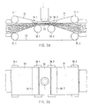
- FIG. 4 schematically shows another preferred measuring point in the area of the sliver deposition, in which area a process section is particularly well suited for the measurement of fiber slivers.
- the sliver between the bottom of the can and the upper part of the sliver is spiraled into an ordered "sliver cake", which is a specific form of continuous sliver of the sliver, and pressed together.
- the latter in that a slidable can bottom presses the band from below against the upper part, with the sliver being continuously inserted between the band cake and the band-laying upper part.
- a relative movement takes place between the surface of the band cake, which is constantly developing, and the upper part of the band deposit; the band cake rotates around the can axis and when the sliver is laid down, new fiber material is always moved past the upper part of the sliver.
- Process conditions are favorable here on the process side.
- a measuring auxiliary device for example a measuring opening W, is arranged in the upper part of the tape storage unit, through which the fiber material pressed from below onto the upper part of the belt storage unit can be illuminated and measured, it is possible for the fiber material which is constantly preparing and self-renewing for the measurement without any intervention to measure in the process flow.
- the continuously laid sliver is guided past the sensor shortly after being laid down and can be measured by it.
- the measuring window is self-cleaning at the interface with the measured material and a cleaning and calibration device (not shown) can be arranged on the sensor side.
- a cleaning and calibration device (not shown) can be arranged on the sensor side.
- the measuring opening in the upper part of the tape deposit is either continuously cleaned of dust, for example by passing an air jet past it, or discontinuously with a mechanical cleaning tool, for example a brush.
- the discontinuous, mechanical cleaning of the measuring opening can be done either off-line or like calibration be carried out manually or automatically controlled or regulated.
- the material to be measured is "opaque", that is, the layer thickness and layer density of the fiber material is so great that the background effect is eliminated, and that the fibers of the material to be measured (after the card or stretching) cleaned and organized (parallelized) and stored in a regular arrangement (as a band cake), which is why the measurement is not affected by changes in time.
- the fiber sliver is not guided past the sensor in the direction of its natural longitudinal orientation, so that fluctuations in brightness occur. This influence can be counteracted by using an auxiliary sensor upstream in the process direction to determine the strip density, for example a capacitive sensor, and using this to trigger the color measurement for the measuring process.
- the preferred measuring location in the process flow is, as already mentioned, on the tape storage, more precisely in the tape storage upper part.
- a specific observation point for the material to be measured which is matched to the process, is arranged in the form of a measurement opening W, which is suitable for a color measurement of the proposed type.
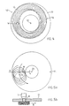
- a can 52 shows band cake layers 56 of a sliver 54 lying on the can bottom 51. This position, which is eccentrically arranged around the can pivot point 32, is covered by additional layers which are eccentrically shifted in the direction of rotation, so that the can bottom is completely covered after a few band cake layers. This is usually the case after less than a minute of filling.
- the surface of the band cake stack then consists of a macroscopically complicated arrangement of fiber band courses, which, however, viewed through the measuring opening, always show the same fiber course due to their total movement around a center of rotation and are conditioned for the measurement by the process-inherent pressing of the band cake layers on the upper part of the band storage.
- 5a and 5b show another process-specific way of depositing the slivers, in which the sliver is laid down around a first and second center of rotation in such a way that the slivers are arranged spirally around a center.
- the fiber slivers are pressed against the upper part of the sliver by the can bottom.
- the measuring opening W to which the uppermost sliver layer B is pressed and moved past (see FIG. 5b), is arranged in the upper part of the sliver.
- the measurement opening can be closed, for example, by a face plate or else open (the band-side hole edges then being rounded off accordingly).
- a measuring opening if circular, is approx. 10 millimeters in diameter, so that both options can be considered: minimizing optical interfaces by omitting a face plate or enlarging the measuring opening, which usually requires the use of a face plate.
- Non-planar optical means such as imaging lenses, can also be used. Such agents are described in European patent application EP-A-0446808.
- the position of the measuring opening can be selected so that the structure of the compressed fiber material passing under the measuring opening is at its finest, which is usually the case on the inner edge of the pressed band cake.
- the position of the measuring point can be optimized in this way.
- color values of the card sliver are measured at intervals of, for example, 10 seconds.
- the can change interrupts the color measurements for about 5-10% of the time it takes to fill a can. This is a blind phase in the measurement process or a measurement gap.
- This measurement gap in which no color measurement data can be obtained, can be reduced or eliminated by placing additional jug shelves in parallel running cards of the same range, additional color sensors can be used. If the can change is organized in time so that color data is always obtained from at least one of the sensors during the change, it is possible to measure the color of the fiber material virtually continuously. The fact that all cans are exchanged with each other can practically be ruled out, especially if organizational measures regarding the time of the cans change are added.
- a second measuring point also has other advantages, namely redundancy due to twice as many measurements if measurements are carried out simultaneously (only during the short time of changing the can does redundancy cease).
- the signals obtained by measuring the concentration mentioned can be evaluated in a controller in such a way that either the proportion of e.g. Synthetic fibers can be displayed in the entire fiber structure on a screen (not shown) or used in a controller prescribed in EP-A-0 362 538 to influence the mixture.
Landscapes
- Engineering & Computer Science (AREA)
- Textile Engineering (AREA)
- Health & Medical Sciences (AREA)
- Life Sciences & Earth Sciences (AREA)
- Chemical & Material Sciences (AREA)
- Food Science & Technology (AREA)
- Medicinal Chemistry (AREA)
- Physics & Mathematics (AREA)
- Analytical Chemistry (AREA)
- Biochemistry (AREA)
- General Health & Medical Sciences (AREA)
- General Physics & Mathematics (AREA)
- Immunology (AREA)
- Pathology (AREA)
- Preliminary Treatment Of Fibers (AREA)
- Treatment Of Fiber Materials (AREA)
- Investigating Materials By The Use Of Optical Means Adapted For Particular Applications (AREA)
Claims (13)
- Procédé servant à examiner un mélange formé de différents types de fibres, et où un assemblage de fibres est formé à partir du mélange,
caractérisé par le fait que
l'assemblage de fibres, en tant que mélange total, est soumis à un procédé de mesure, à l'aide duquel la concentration des types individuels de fibres, prédéterminés dans l'assemblage de fibres, peut être détectée par analyse de spectres dans la zone proche des infrarouges, et que les signaux obtenus par cette mesure sont évalués dans un asservissement, afin de déterminer la quantité d'au moins un type de fibres dans le mélange total. - Procédé selon revendication 1,
caractérisé par le fait que
la mesure est exécutée pendant le déplacement de l'assemblage de fibres. - Procédé selon revendication 1 ou 2,
caractérisé par le fait que
la mesure est exécutée à un endroit où une condensation de l'assemblage de fibres est réalisée par rassemblement ou compression. - Procédé selon une des revendications 1 à 3,
caractérisé par le fait que
la mesure est réalisée par illumination de l'assemblage de fibres, et où, au lieu de mesure, un guidage de lumière est agencé de telle sorte que le processus de déroulement n'est pas entravé, et, par ce guidage de lumière, la lumière réfléchie par la matière à mesurer est interceptée perpendiculairement à l'axe longitudinal de l'assemblage de fibres, et est évaluée. - Procédé selon revendication 4,
caractérisé par le fait que,
comme lieu de mesure, un endroit est choisi dans lequel l'assemblage de fibres est déposé en couches qui se superposent. - Procédé selon une des revendications 1 à 5,
caractérisé par le fait que
le mélange est constitué par des composants de mélange qui sont variables d'une manière commandable, et la commande du procédé de mélange est réalisée en fonction des signaux évalués par l'asservissement. - Procédé selon une des revendications 1 à 6,
caractérisé par le fait que
le mélange comprend aussi bien des fibres naturelles que des fibres fabriquées d'une manière artificielle, et la quantité des fibres artificielles est détectée. - Procédé selon une des revendications 1 à 7,
caractérisé par le fait que
le lieu de processus est choisi de telle manière que la mesure est exécutée sur un ruban de carde. - Dispositif servant à examiner un mélange formé de différents types de fibres, lequel se présente sous forme d'un assemblage de fibres,
caractérisé par le fait
qu'un appareil de mesure sous forme d'un spectromètre infrarouge et un asservissement sont prévus, et où l'assemblage de fibres peut être guidé vers l'appareil de mesure en tant que mélange total, et l'appareil est approprié pour déterminer la concentration des types individuels de fibres, prédéterminés dans l'assemblage de fibres, et pour guider vers l'asservissement des signaux obtenus par cette mesure, et où l'asservissement peut évaluer ces signaux, afin de déterminer la quantité d'au moins un type de fibres dans le mélange total. - Dispositif selon revendication 9,
caractérisé par le fait
qu'un moyen est prévu qui comprime la matière fibreuse lors de son amenée dans le lieu de mesure. - Dispositif selon revendication 9 ou 10,
caractérisé par le fait que
le lieu de mesure comprend un entonnoir de ruban (22) et une sonde de mesure disposée perpendiculairement au col d'entonnoir (23), et que le col d'entonnoir (23) est pourvu d'une ouverture de passage dont la section présente la forme d'un rectangle applati, et dont la paroi (24) faisant face à la sonde de mesure, est transparente, alors que la paroi opposée (25) ne possède aucune caractéristique particulière concernant la mesure. - Dispositif selon une des revendications 9 à 11,
caractérisé par le fait que
le dispositif comprend, des deux côtés de l'assemblage de fibres, au moins une courroie de bande transporteuse (30,31,32), et, sur un côté de l'assemblage de fibres, il comprend une plaque transparente (34) et une sonde de mesure (1) disposée du côté opposé au côté de la plaque transparante faisant face à l'assemblage de fibres, et que les courroies de bande transporteuse et la plaque transparente sont disposées de telle manière que, vu dans le sens de déplacement des bandes, la distance entre celles-ci diminue successivement en allant vers la plaque transparente, et possède un minimum dans les environs de la plaque transparente. - Dispositif selon revendication 12,
caractérisé par le fait que,
du côté de la mesure de l'assemblage de fibres, la plaque transparente (34) est diposée entre deux courroies de bande transporteuse, dont une d'entrée (30) et une de sortie (31), et que les courroies (30 et 31) sont guidées immédiatement près de la plaque transparente (34) à l'aide de coulisses (36.1/2) en forme de plaques.
Applications Claiming Priority (2)
| Application Number | Priority Date | Filing Date | Title |
|---|---|---|---|
| CH349690 | 1990-11-02 | ||
| CH3496/90 | 1990-11-02 |
Publications (2)
| Publication Number | Publication Date |
|---|---|
| EP0483607A1 EP0483607A1 (fr) | 1992-05-06 |
| EP0483607B1 true EP0483607B1 (fr) | 1997-04-23 |
Family
ID=4257251
Family Applications (1)
| Application Number | Title | Priority Date | Filing Date |
|---|---|---|---|
| EP91117712A Expired - Lifetime EP0483607B1 (fr) | 1990-11-02 | 1991-10-17 | Procédé pour identifier la qualité d'un matériau fibreux |
Country Status (4)
| Country | Link |
|---|---|
| US (1) | US5355561A (fr) |
| EP (1) | EP0483607B1 (fr) |
| JP (1) | JPH04265848A (fr) |
| DE (1) | DE59108679D1 (fr) |
Families Citing this family (9)
| Publication number | Priority date | Publication date | Assignee | Title |
|---|---|---|---|---|
| US5430301A (en) * | 1990-03-14 | 1995-07-04 | Zellweger Uster, Inc. | Apparatus and methods for measurement and classification of generalized neplike entities in fiber samples |
| US6088094A (en) * | 1997-12-23 | 2000-07-11 | Zellweger Uster, Inc. | On-line sliver monitor |
| CN1245546C (zh) * | 1999-12-16 | 2006-03-15 | 乌斯特技术股份公司 | 识别并排出由压实纺织纤维组成的纤维流中的异物的方法和装置 |
| CN1735803A (zh) * | 2003-01-08 | 2006-02-15 | 乌斯特技术股份公司 | 对纵向运动的纺织检验物料中的杂质检测和分级的方法 |
| DE102004028358A1 (de) * | 2004-06-11 | 2005-12-29 | Trützschler GmbH & Co KG | Vorrichtung für eine bandbildende Textilmaschine, insbesondere Strecke, Karde o. dgl., mit einer Vliesführung |
| DE102006057215B4 (de) * | 2006-12-01 | 2022-08-11 | Trützschler GmbH & Co Kommanditgesellschaft | Vorrichtung an einer Spinnereivorbereitungsanlage zum Erkennen von Fremdstoffen in Fasergut |
| CN101493449B (zh) * | 2008-12-19 | 2012-06-27 | 清华大学深圳研究生院 | 纤维鉴别方法及混纺织物中纤维成分含量的测量方法 |
| US11402335B2 (en) | 2017-09-14 | 2022-08-02 | Uster Technologies Ag | Fiber blend identification and ratio measurement |
| CN113019983A (zh) * | 2021-03-04 | 2021-06-25 | 韦李飞 | 纤维特征识别及分拣系统 |
Family Cites Families (33)
| Publication number | Priority date | Publication date | Assignee | Title |
|---|---|---|---|---|
| DE277331C (fr) * | ||||
| DE362538C (de) * | 1916-06-28 | 1922-10-28 | Hermann Staudinger Dr | Verfahren zur Darstellung von Malonsaeure |
| US3471702A (en) * | 1967-09-29 | 1969-10-07 | Du Pont | Method for measuring bulk level of yarn |
| US3524988A (en) * | 1967-11-16 | 1970-08-18 | Du Pont | Process and apparatus for evaluating fabric appearance |
| US3573476A (en) * | 1968-11-20 | 1971-04-06 | Du Pont | Apparatus for determining reflective color index of fibrous samples |
| DE1931929C3 (de) * | 1969-06-24 | 1980-08-07 | Zinser Textilmaschinen Gmbh, 7333 Ebersbach | Vorrichtung zum Vergleichmäßigen von textlien Faserbändern |
| US3925850A (en) * | 1973-11-01 | 1975-12-16 | Fibers Controls Corp | Density sensing and controlling equipment |
| US4288160A (en) * | 1973-12-28 | 1981-09-08 | Nekoosa Papers Inc. | Optical property measurement system and method |
| US3986778A (en) * | 1975-10-01 | 1976-10-19 | International Business Machines Corporation | Spectrophotometer sample holder |
| US4022534A (en) * | 1976-03-23 | 1977-05-10 | Kollmorgen Corporation | Reflectometer optical system |
| DE2910673C2 (de) * | 1979-03-19 | 1985-08-08 | Paul Lippke Gmbh & Co Kg, 5450 Neuwied | Verfahren zum berührungslosen Messen des absoluten Gehaltes eines Stoffes(Beisubstanz) in einer die Form eines dünnen Filmes aufweisenden Mischung(Hauptsubstanz und Beisubstanz) mehrerer Stoffe, insbesondere zum Messen des absoluten Gehaltes von Wasser in Papier |
| US4284356A (en) * | 1979-09-26 | 1981-08-18 | Ppg Industries, Inc. | Method of and apparatus for comparing surface reflectivity |
| US4306450A (en) * | 1979-10-15 | 1981-12-22 | Rieter Machine Works, Ltd. | Apparatus for measuring a cross-sectional area of a travelling fiber sliver |
| DE3204146C2 (de) * | 1982-02-06 | 1986-06-19 | Bundesrepublik Deutschland, vertreten durch den Bundesminister für Wirtschaft in Bonn, dieser vertreten durch den Präsidenten der Bundesanstalt für Materialprüfung (BAM), 1000 Berlin | Infrarotthermographie-Reflexionsverfahren |
| US4490618A (en) * | 1982-04-12 | 1984-12-25 | Canadian Patents & Development Limited | Optical system for analyzing the surface of a fibrous web |
| DE3327966A1 (de) * | 1983-08-03 | 1985-02-21 | Fritz 7347 Bad Überkingen Stahlecker | Streckwerk fuer spinnereimaschinen |
| GB2172102B (en) * | 1985-03-09 | 1988-10-19 | Haigh Chadwick Ltd | Textile structure measurement |
| US4758968A (en) * | 1985-05-16 | 1988-07-19 | North Carolina State University | Method and apparatus for continuously measuring the variability of textile strands |
| US4786817A (en) * | 1986-08-29 | 1988-11-22 | Measurex Corporation | System and method for measurement of traveling webs |
| DE3643764A1 (de) * | 1986-12-20 | 1988-06-30 | Lippke Gmbh Co Kg Paul | Verfahren zur selektiven fuellstoffmessung an laufenden materialbahnen, insbesondere papierbahnen |
| US4766647A (en) * | 1987-04-10 | 1988-08-30 | Spinlab Partners, Ltd. | Apparatus and method for measuring a property of a continuous strand of fibrous materials |
| JPS6432153A (en) * | 1987-07-29 | 1989-02-02 | Yokogawa Electric Corp | Method and instrument for measuring characteristic of sheet type material |
| JPH0797082B2 (ja) * | 1987-10-06 | 1995-10-18 | 日本電子株式会社 | 赤外放射分光測定方法及び装置 |
| DE3734145A1 (de) * | 1987-10-09 | 1989-04-27 | Hollingsworth Gmbh | Verfahren und vorrichtung zum reinigen und oeffnen von in flockenform befindlichem fasergut, z. b. baumwolle |
| EP0322470B1 (fr) * | 1987-12-24 | 1991-12-04 | Barco Automation, Naamloze Vennootschap | Dispositif pour mesurer un fil |
| DE3827866A1 (de) * | 1988-04-30 | 1990-03-08 | Hoechst Ag | Verfahren zur messung des verwirbelungsgrades und dazu geeignete messvorrichtung |
| AU629231B2 (en) * | 1988-09-06 | 1992-10-01 | Maschinenfabrik Rieter A.G. | A method of blending textile fibres |
| DE3834110A1 (de) * | 1988-10-07 | 1990-04-12 | Truetzschler & Co | Verfahren und vorrichtung zur bewegungserfassung von textilfaserbaendern, z. b. kardenbaendern |
| AU636884B2 (en) * | 1989-05-23 | 1993-05-13 | Maschinenfabrik Rieter A.G. | Optimisation of cleaning |
| CH678172A5 (fr) * | 1989-06-07 | 1991-08-15 | Zellweger Uster Ag | |
| DE3924208A1 (de) * | 1989-07-21 | 1991-01-24 | Schubert & Salzer Maschinen | Verfahren zur herstellung eines fadens aus fasermaterial |
| CH680931A5 (fr) * | 1990-03-08 | 1992-12-15 | Loepfe Ag Geb | |
| ATE121539T1 (de) * | 1990-03-12 | 1995-05-15 | Rieter Ag Maschf | Verfahren und vorrichtung zur messung der eigenfarbe von faserbändern. |
-
1991
- 1991-10-17 EP EP91117712A patent/EP0483607B1/fr not_active Expired - Lifetime
- 1991-10-17 DE DE59108679T patent/DE59108679D1/de not_active Expired - Fee Related
- 1991-10-30 US US06/785,064 patent/US5355561A/en not_active Expired - Fee Related
- 1991-11-01 JP JP3287542A patent/JPH04265848A/ja active Pending
Also Published As
| Publication number | Publication date |
|---|---|
| EP0483607A1 (fr) | 1992-05-06 |
| US5355561A (en) | 1994-10-18 |
| DE59108679D1 (de) | 1997-05-28 |
| JPH04265848A (ja) | 1992-09-22 |
Similar Documents
| Publication | Publication Date | Title |
|---|---|---|
| DE3734145C2 (fr) | ||
| DE69031542T2 (de) | Einrichtung zur Messung des Zugwiderstands von Filterzigaretten | |
| DE10214955B4 (de) | Spinnereivorbereitungsmaschine | |
| CH693311A5 (de) | Regulierstreckwerk für Faserverbände. | |
| DE19516568A1 (de) | Vorrichtung in einer Spinnereivorbereitungseinrichtung (Putzerei) zum Erkennen und Ausscheiden von Fremdstoffen, z. B. Gewebestücke, Bänder, Schnüre, Folienstücke, in bzw. aus Fasergut | |
| CH697950B1 (de) | Vorrichtung für eine bandbildende Textilmaschine, insbesondere Strecke oder Karde. | |
| EP0483607B1 (fr) | Procédé pour identifier la qualité d'un matériau fibreux | |
| EP0399315A1 (fr) | Opération de nettoyage optimal | |
| EP0571572B1 (fr) | Peigneuse | |
| EP1316630B1 (fr) | Dispositif et procédé pour mesurer la masse et l'humidité d'une matière fibreuse dans une machine de préparation de filature | |
| DE102005019760B4 (de) | Spinnereimaschine mit einem Streckwerk zum Verstrecken eines Faserverbandes und entsprechendes Verfahren | |
| DE102019115138B3 (de) | Karde, Vliesleitelement, Spinnereivorbereitungsanlage und Verfahren zur Erfassung von störenden Partikeln | |
| DE69327840T2 (de) | Vorrichtung und Verfahren zur Messung und Klassifizierung von Trashteilen in Faserproben | |
| EP0485881B1 (fr) | Procédé et dispositif pour commander une carde | |
| EP0348443B1 (fr) | Dispositif pour determiner automatiquement la finesse d'un echantillon de textile et utilisation du dispositif | |
| CH680536A5 (fr) | ||
| CH695501A5 (de) | Vorrichtung am Ausgang einer Strecke zur Erfassung eines Faserverbands. | |
| EP0446808B1 (fr) | Procédé et dispositif pour mesurer la couleur des mèches de fibres | |
| DE19943079A1 (de) | Vorrichtung an einer Karde oder Krempel, bei der ein Faserflor aus Textilfasern, z.B. Baumwolle, Chemiefasern u.dgl., gebildet ist | |
| DE19732831C2 (de) | Verfahren und Vorrichtung zum Abtasten einer vorzugsweise textilen Warenbahn | |
| EP1943503A1 (fr) | Procede et dispositif de détection de l'encrassement dans un ecoulement de fibres en deplacement | |
| WO2024104692A1 (fr) | Procédé de détection de corps étrangers dans un matériau fibreux | |
| DE8713550U1 (de) | Vorrichtung zum Reinigen und Öffnen von in Flockenform befindlichem Fasergut, z.B. Baumwolle | |
| WO2023117226A1 (fr) | Peigneuse avec surveillance de la blousse | |
| DE20318443U1 (de) | Vorrichtung an einer Spinnereivorbereitungsmaschine, z.B. Reiniger, Öffner, Karde o.dgl., zur Erfassung von aus Fasermaterial, z.B. Baumwolle, ausgeschiedenem Abfall |
Legal Events
| Date | Code | Title | Description |
|---|---|---|---|
| PUAI | Public reference made under article 153(3) epc to a published international application that has entered the european phase |
Free format text: ORIGINAL CODE: 0009012 |
|
| AK | Designated contracting states |
Kind code of ref document: A1 Designated state(s): CH DE FR GB IT LI |
|
| 17P | Request for examination filed |
Effective date: 19920318 |
|
| 17Q | First examination report despatched |
Effective date: 19931123 |
|
| GRAG | Despatch of communication of intention to grant |
Free format text: ORIGINAL CODE: EPIDOS AGRA |
|
| GRAH | Despatch of communication of intention to grant a patent |
Free format text: ORIGINAL CODE: EPIDOS IGRA |
|
| GRAH | Despatch of communication of intention to grant a patent |
Free format text: ORIGINAL CODE: EPIDOS IGRA |
|
| GRAA | (expected) grant |
Free format text: ORIGINAL CODE: 0009210 |
|
| AK | Designated contracting states |
Kind code of ref document: B1 Designated state(s): CH DE FR GB IT LI |
|
| PG25 | Lapsed in a contracting state [announced via postgrant information from national office to epo] |
Ref country code: FR Effective date: 19970423 |
|
| REG | Reference to a national code |
Ref country code: CH Ref legal event code: EP |
|
| REF | Corresponds to: |
Ref document number: 59108679 Country of ref document: DE Date of ref document: 19970528 |
|
| GBT | Gb: translation of ep patent filed (gb section 77(6)(a)/1977) |
Effective date: 19970617 |
|
| EN | Fr: translation not filed | ||
| PLBE | No opposition filed within time limit |
Free format text: ORIGINAL CODE: 0009261 |
|
| STAA | Information on the status of an ep patent application or granted ep patent |
Free format text: STATUS: NO OPPOSITION FILED WITHIN TIME LIMIT |
|
| 26N | No opposition filed | ||
| PGFP | Annual fee paid to national office [announced via postgrant information from national office to epo] |
Ref country code: CH Payment date: 19980929 Year of fee payment: 8 |
|
| PG25 | Lapsed in a contracting state [announced via postgrant information from national office to epo] |
Ref country code: LI Free format text: LAPSE BECAUSE OF NON-PAYMENT OF DUE FEES Effective date: 19991031 Ref country code: CH Free format text: LAPSE BECAUSE OF NON-PAYMENT OF DUE FEES Effective date: 19991031 |
|
| REG | Reference to a national code |
Ref country code: CH Ref legal event code: PL |
|
| PGFP | Annual fee paid to national office [announced via postgrant information from national office to epo] |
Ref country code: GB Payment date: 20010924 Year of fee payment: 11 |
|
| REG | Reference to a national code |
Ref country code: GB Ref legal event code: IF02 |
|
| PGFP | Annual fee paid to national office [announced via postgrant information from national office to epo] |
Ref country code: DE Payment date: 20020925 Year of fee payment: 12 |
|
| PG25 | Lapsed in a contracting state [announced via postgrant information from national office to epo] |
Ref country code: GB Free format text: LAPSE BECAUSE OF NON-PAYMENT OF DUE FEES Effective date: 20021017 |
|
| GBPC | Gb: european patent ceased through non-payment of renewal fee |
Effective date: 20021017 |
|
| PG25 | Lapsed in a contracting state [announced via postgrant information from national office to epo] |
Ref country code: DE Free format text: LAPSE BECAUSE OF NON-PAYMENT OF DUE FEES Effective date: 20040501 |
|
| PG25 | Lapsed in a contracting state [announced via postgrant information from national office to epo] |
Ref country code: IT Free format text: LAPSE BECAUSE OF NON-PAYMENT OF DUE FEES;WARNING: LAPSES OF ITALIAN PATENTS WITH EFFECTIVE DATE BEFORE 2007 MAY HAVE OCCURRED AT ANY TIME BEFORE 2007. THE CORRECT EFFECTIVE DATE MAY BE DIFFERENT FROM THE ONE RECORDED. Effective date: 20051017 |