EP0483607B1 - Method for identifying the quality of a fiber material - Google Patents
Method for identifying the quality of a fiber material Download PDFInfo
- Publication number
- EP0483607B1 EP0483607B1 EP91117712A EP91117712A EP0483607B1 EP 0483607 B1 EP0483607 B1 EP 0483607B1 EP 91117712 A EP91117712 A EP 91117712A EP 91117712 A EP91117712 A EP 91117712A EP 0483607 B1 EP0483607 B1 EP 0483607B1
- Authority
- EP
- European Patent Office
- Prior art keywords
- measuring
- sliver
- fibre bundle
- mixture
- measurement
- Prior art date
- Legal status (The legal status is an assumption and is not a legal conclusion. Google has not performed a legal analysis and makes no representation as to the accuracy of the status listed.)
- Expired - Lifetime
Links
- 238000000034 method Methods 0.000 title claims description 51
- 239000002657 fibrous material Substances 0.000 title description 7
- 239000000835 fiber Substances 0.000 claims description 47
- 238000005259 measurement Methods 0.000 claims description 37
- 239000000203 mixture Substances 0.000 claims description 21
- 239000000523 sample Substances 0.000 claims description 9
- 229920002994 synthetic fiber Polymers 0.000 claims description 8
- 239000000463 material Substances 0.000 claims description 7
- 238000002156 mixing Methods 0.000 claims description 4
- 238000003825 pressing Methods 0.000 claims description 3
- 230000001771 impaired effect Effects 0.000 claims description 2
- 238000001228 spectrum Methods 0.000 claims description 2
- 230000007423 decrease Effects 0.000 claims 1
- 238000011156 evaluation Methods 0.000 claims 1
- 238000005286 illumination Methods 0.000 claims 1
- 230000006835 compression Effects 0.000 description 13
- 238000007906 compression Methods 0.000 description 13
- 238000003860 storage Methods 0.000 description 8
- 239000012209 synthetic fiber Substances 0.000 description 5
- 238000004140 cleaning Methods 0.000 description 4
- 238000000151 deposition Methods 0.000 description 4
- 239000004753 textile Substances 0.000 description 4
- 229920000742 Cotton Polymers 0.000 description 3
- 230000001105 regulatory effect Effects 0.000 description 3
- 230000000694 effects Effects 0.000 description 2
- 239000011521 glass Substances 0.000 description 2
- 230000007774 longterm Effects 0.000 description 2
- 230000003287 optical effect Effects 0.000 description 2
- 238000012545 processing Methods 0.000 description 2
- 230000015572 biosynthetic process Effects 0.000 description 1
- 239000007795 chemical reaction product Substances 0.000 description 1
- 239000003795 chemical substances by application Substances 0.000 description 1
- 230000001143 conditioned effect Effects 0.000 description 1
- 230000008021 deposition Effects 0.000 description 1
- 238000013461 design Methods 0.000 description 1
- 238000001514 detection method Methods 0.000 description 1
- 239000000428 dust Substances 0.000 description 1
- 230000002349 favourable effect Effects 0.000 description 1
- 238000009499 grossing Methods 0.000 description 1
- 238000003384 imaging method Methods 0.000 description 1
- 239000013067 intermediate product Substances 0.000 description 1
- 230000004807 localization Effects 0.000 description 1
- 239000000047 product Substances 0.000 description 1
- 238000005204 segregation Methods 0.000 description 1
- 239000000126 substance Substances 0.000 description 1
- 238000012360 testing method Methods 0.000 description 1
- 239000012780 transparent material Substances 0.000 description 1
- 238000011144 upstream manufacturing Methods 0.000 description 1
Images
Classifications
-
- D—TEXTILES; PAPER
- D01—NATURAL OR MAN-MADE THREADS OR FIBRES; SPINNING
- D01G—PRELIMINARY TREATMENT OF FIBRES, e.g. FOR SPINNING
- D01G31/00—Warning or safety devices, e.g. automatic fault detectors, stop motions
- D01G31/006—On-line measurement and recording of process and product parameters
-
- D—TEXTILES; PAPER
- D01—NATURAL OR MAN-MADE THREADS OR FIBRES; SPINNING
- D01G—PRELIMINARY TREATMENT OF FIBRES, e.g. FOR SPINNING
- D01G13/00—Mixing, e.g. blending, fibres; Mixing non-fibrous materials with fibres
-
- G—PHYSICS
- G01—MEASURING; TESTING
- G01N—INVESTIGATING OR ANALYSING MATERIALS BY DETERMINING THEIR CHEMICAL OR PHYSICAL PROPERTIES
- G01N33/00—Investigating or analysing materials by specific methods not covered by groups G01N1/00 - G01N31/00
- G01N33/36—Textiles
- G01N33/365—Textiles filiform textiles, e.g. yarns
Definitions
- each provenance has predetermined fiber properties and in which each provenance is a mixed component of a predetermined percentage, and in which the mixture as a whole has predetermined fiber properties and the mixing components are controllable variable components at all times.
- the percentage of each component in order to achieve the fiber properties of the mixture mentioned is automatically optimized, taking into account the fiber properties of the individual components, by the component mixture depending on predetermined and determined properties of a subsequently produced intermediate product, preferably a card sliver or a subsequently produced end product , preferably a yarn, are determined and corrected immediately and automatically in the event of deviations therefrom.
- the process of the European patent application mentioned shows and describes the possibility of transferring the textile fibers of different provenance either directly from the fiber bales or from component cells to a mixer in which these components are mixed homogeneously.
- the product of the mixer is then cleaned in a blow room and then handed over for processing a card.
- the card sliver is checked in a color testing device and the corresponding signal is sent to a controller that controls the component mixture.
- provenance can be understood to mean cotton fiber bales or fiber bales with synthetic fibers, so that the mixture can be mixtures of different types of cotton or a mixture of cotton fibers and man-made fibers.
- US-A-4,758,968 describes a method and an apparatus for the continuous measurement of changes in textile fiber slivers. For this purpose, the changes of one or more parameters of the textile fiber sliver should be measured. It can be seen from the first exemplary embodiments that the signal from a signal converter which has at least one parameter, e.g. the linear fiber density, monitored, is processed in three different signal-integrating and signal-smoothing circuits with a different time constant. Long-term errors in a range of wavelength bands can be extracted from this.
- the further exemplary embodiments (FIGS. 9 to 12) furthermore show that a plurality of signal converters can also be used to observe the long-term changes in a parameter. However, these measurements cannot be used to determine the proportions of the mixture in a fiber structure.
- a process point at which the fiber structure is deposited in overlapping layers can be selected as the measuring point.
- the advantage of the invention is that the mixture of natural and artificial fibers can be determined in a relatively simple manner in an earlier stage of the fiber processing process with sufficiently high accuracy, which is particularly advantageous because the artificial fibers usually have a significantly different price than the natural fibers and therefore exact compliance with the synthetic fiber content is required by law in different countries.
- a measuring probe 1 shows a measuring probe 1, which is arranged perpendicular to the running direction B of a fiber structure or also a fiber band and the band surface is guided past it at a constant distance from it.
- the measurement could also be carried out on a stationary fiber structure.
- the sliver is slightly compressed by compression means 2 before it passes through the measuring point.
- the measurement is made through an appropriately transparent device part 3 (plane glass pane) or through a small opening (without plane glass pane) between the compression means.
- Appropriate design of the compression means be it process-related or purely measurement-related, ensures that the tape at the measuring point has a sufficient width to cover the entire measuring opening of the measuring probe.
- the above concentration is measured by evaluating spectra in the near infrared range using an FT-NIR spectrometer from Buhler, CH-9240 Uzwil.
- variant 1 Three process variants are available for compressing the sliver in the area of the measuring point.
- the measurement is carried out at a process point at which the sliver is compressed due to the process, i.e. where the compression means 2b, e.g. a funnel represents a process-specific device part.
- the compression means 2b e.g. a funnel represents a process-specific device part.
- the measurement is carried out at any process point, and the sliver is compressed in the area of the measuring point without braking, between compression means 2c running with the band.
- FIG. 2 shows an exemplary embodiment of the measuring device according to the invention.
- Process-related compression in a funnel is used for the compression of the fiber sliver, so method variant 1 (FIG. 1b) is used.
- FIG. 2a it can be the funnel of a tape depositing device, such as those used for tape depositing in cans.
- it can also be the feed hopper for a pair of stepped rollers or a measuring hopper that is installed for measuring the strip density.
- FIG. 2a shows, as an example of a localization of the device according to the invention, schematically the exit of the fiber sliver from a card 20 and its feeding to a card Tape deposit device 21 on a can 211.
- the measuring probe 1 is installed on the hopper 22 of the tape deposit device.
- the funnel 22 is specially designed for this purpose.
- the funnel neck 23 is designed as a measuring cuvette. So that the continuous band has a width sufficient for the measurement, the funnel neck 23 has the cross section shown in FIG. 2c with the shape of a very flat rectangle with rounded corners.
- the wide side 24 of the funnel neck 23 facing the measuring probe consists of a transparent material.
- a few transport rollers 26 follow the storage hopper in the direction of the wall.
- FIG. 2d shows the control of the loop formation based on FIG. 1d, which is described, for example, in DE-B-1931929 and in this form likewise requires the can filling to be started and stopped at Measurement.
- FIG. 3 shows a side view (FIG. 3a) and a top view (FIG. 3b) of an exemplary embodiment of the device according to the invention, which is suitable for carrying out the method according to the invention, and in which the continuous sliver according to process variant II (FIG. 1c ) is compressed specifically for the measurement.
- the device can be used at any process point where a sliver is freely transported over a sufficiently long distance. Since the sliver must not be slowed down by the compression, it must be actively transported through the measuring section.
- the sliver is transported, for example, by endless belts 30, 31 and 32, the belts 30 and 31 being aligned in a straight line, with a transparent plate 34 lying between them on one side, the belt 32 on the other side of the
- the sliver is arranged in such a way that a narrowed measuring section is formed between the transparent plate 34 and the belt 32.
- the belt 32 thus also acts as a compression means.
- the measuring probe 1 is positioned on the side of the transparent plate facing away from the sliver.
- the plate 43 is the only part that comes into contact with the continuous belt, stationary. However, since the belt is transported through the belts on both sides of the plate, the braking effect is negligible.
- the transparent plate 34 can also be omitted and the measurement can be carried out through a corresponding gap between the belts 30 and 31.
- the two belts 30 and 31 are driven by the drive rollers 35.1 and 35.2 and are guided adjacent to the transparent plate 34 around two plate-shaped links 36.1 and 36.2.
- By using such plate-shaped backdrops it is possible, on the one hand, to guide the belts up to the transparent plate 34 in the same plane in which the plate 34 lies, and, on the other hand, there is space on the side of the plate 34 facing away from the continuous sliver to be sufficiently close to the measuring probe to position on the plate 34.
- Similar belt drives are e.g. known from DE-A-3327966, which describes the use of such belt drives in a drafting system.
- the belt 32 is driven by two drive rollers 37.1 and 37.2 and guided over two trailed rollers 38.1 and 38.2.
- the distance between the rollers 37 and the belts 30 and 31 corresponds approximately to the thickness of the tape fed to the measuring point.
- the distance between the rollers 38 and the belts 30 and 31 is smaller and corresponds to the compression level of the sliver suitable for the color measurement.
- the device does not change the sliver in any way, that is, does not stretch or brake in particular, it is very important that the belt speeds of the belts 30, 31 and 32 correspond exactly to the transport speed of the sliver at the corresponding process point. If this speed is constant, the speed of the drive rollers 35 and 37 must be set accordingly. If this speed is not constant, such as at the exit of a drafting system, the drafting roller speeds of which are above the strip thickness are regulated, the speeds of the drive rollers 35 and 37 must also be regulated by this regulation.
- FIG. 4 schematically shows another preferred measuring point in the area of the sliver deposition, in which area a process section is particularly well suited for the measurement of fiber slivers.
- the sliver between the bottom of the can and the upper part of the sliver is spiraled into an ordered "sliver cake", which is a specific form of continuous sliver of the sliver, and pressed together.
- the latter in that a slidable can bottom presses the band from below against the upper part, with the sliver being continuously inserted between the band cake and the band-laying upper part.
- a relative movement takes place between the surface of the band cake, which is constantly developing, and the upper part of the band deposit; the band cake rotates around the can axis and when the sliver is laid down, new fiber material is always moved past the upper part of the sliver.
- Process conditions are favorable here on the process side.
- a measuring auxiliary device for example a measuring opening W, is arranged in the upper part of the tape storage unit, through which the fiber material pressed from below onto the upper part of the belt storage unit can be illuminated and measured, it is possible for the fiber material which is constantly preparing and self-renewing for the measurement without any intervention to measure in the process flow.
- the continuously laid sliver is guided past the sensor shortly after being laid down and can be measured by it.
- the measuring window is self-cleaning at the interface with the measured material and a cleaning and calibration device (not shown) can be arranged on the sensor side.
- a cleaning and calibration device (not shown) can be arranged on the sensor side.
- the measuring opening in the upper part of the tape deposit is either continuously cleaned of dust, for example by passing an air jet past it, or discontinuously with a mechanical cleaning tool, for example a brush.
- the discontinuous, mechanical cleaning of the measuring opening can be done either off-line or like calibration be carried out manually or automatically controlled or regulated.
- the material to be measured is "opaque", that is, the layer thickness and layer density of the fiber material is so great that the background effect is eliminated, and that the fibers of the material to be measured (after the card or stretching) cleaned and organized (parallelized) and stored in a regular arrangement (as a band cake), which is why the measurement is not affected by changes in time.
- the fiber sliver is not guided past the sensor in the direction of its natural longitudinal orientation, so that fluctuations in brightness occur. This influence can be counteracted by using an auxiliary sensor upstream in the process direction to determine the strip density, for example a capacitive sensor, and using this to trigger the color measurement for the measuring process.
- the preferred measuring location in the process flow is, as already mentioned, on the tape storage, more precisely in the tape storage upper part.
- a specific observation point for the material to be measured which is matched to the process, is arranged in the form of a measurement opening W, which is suitable for a color measurement of the proposed type.
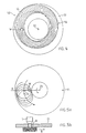
- a can 52 shows band cake layers 56 of a sliver 54 lying on the can bottom 51. This position, which is eccentrically arranged around the can pivot point 32, is covered by additional layers which are eccentrically shifted in the direction of rotation, so that the can bottom is completely covered after a few band cake layers. This is usually the case after less than a minute of filling.
- the surface of the band cake stack then consists of a macroscopically complicated arrangement of fiber band courses, which, however, viewed through the measuring opening, always show the same fiber course due to their total movement around a center of rotation and are conditioned for the measurement by the process-inherent pressing of the band cake layers on the upper part of the band storage.
- 5a and 5b show another process-specific way of depositing the slivers, in which the sliver is laid down around a first and second center of rotation in such a way that the slivers are arranged spirally around a center.
- the fiber slivers are pressed against the upper part of the sliver by the can bottom.
- the measuring opening W to which the uppermost sliver layer B is pressed and moved past (see FIG. 5b), is arranged in the upper part of the sliver.
- the measurement opening can be closed, for example, by a face plate or else open (the band-side hole edges then being rounded off accordingly).
- a measuring opening if circular, is approx. 10 millimeters in diameter, so that both options can be considered: minimizing optical interfaces by omitting a face plate or enlarging the measuring opening, which usually requires the use of a face plate.
- Non-planar optical means such as imaging lenses, can also be used. Such agents are described in European patent application EP-A-0446808.
- the position of the measuring opening can be selected so that the structure of the compressed fiber material passing under the measuring opening is at its finest, which is usually the case on the inner edge of the pressed band cake.
- the position of the measuring point can be optimized in this way.
- color values of the card sliver are measured at intervals of, for example, 10 seconds.
- the can change interrupts the color measurements for about 5-10% of the time it takes to fill a can. This is a blind phase in the measurement process or a measurement gap.
- This measurement gap in which no color measurement data can be obtained, can be reduced or eliminated by placing additional jug shelves in parallel running cards of the same range, additional color sensors can be used. If the can change is organized in time so that color data is always obtained from at least one of the sensors during the change, it is possible to measure the color of the fiber material virtually continuously. The fact that all cans are exchanged with each other can practically be ruled out, especially if organizational measures regarding the time of the cans change are added.
- a second measuring point also has other advantages, namely redundancy due to twice as many measurements if measurements are carried out simultaneously (only during the short time of changing the can does redundancy cease).
- the signals obtained by measuring the concentration mentioned can be evaluated in a controller in such a way that either the proportion of e.g. Synthetic fibers can be displayed in the entire fiber structure on a screen (not shown) or used in a controller prescribed in EP-A-0 362 538 to influence the mixture.
Description
Aus der europäischen Patentanmeldung EP-A-0 362 538 der Anmelderin ist ein Verfahren zum Mischen von Textilfasern von unterschiedlicher Provenienz bekannt, in welchem jede Provenienz vorgegebene Fasereigenschaften aufweist und in welchem jede Provenienz eine Mischkomponente von vorgegebenem prozentualen Anteil ist, sowie in welchem die Mischung als Ganzes vorgegebene Fasereigenschaften aufweist und die Mischkomponenten jederzeit steuerbar variable Komponenten sind. Dabei ist der prozentuale Anteil jeder Komponente, um die genannten Fasereigenschaften der Mischung zu erreichen, unter Berücksichtigung der Fasereigenschaften der einzelnen Komponenten automatisch optimiert, indem die Komponentenmischung in Abhängigkeit von vorgegebenen und festgestellten Eigenschaften eines nachfolgend hergestellten Zwischenproduktes, vorzugsweise eines Kardenbandes oder eines nachfolgend hergestellten Endproduktes, vorzugsweise eines Garnes, bestimmt und bei Abweichungen davon unverzüglich und automatisch korrigiert werden.From the European patent application EP-A-0 362 538 by the applicant, a method for mixing textile fibers of different provenance is known, in which each provenance has predetermined fiber properties and in which each provenance is a mixed component of a predetermined percentage, and in which the mixture as a whole has predetermined fiber properties and the mixing components are controllable variable components at all times. The percentage of each component in order to achieve the fiber properties of the mixture mentioned is automatically optimized, taking into account the fiber properties of the individual components, by the component mixture depending on predetermined and determined properties of a subsequently produced intermediate product, preferably a card sliver or a subsequently produced end product , preferably a yarn, are determined and corrected immediately and automatically in the event of deviations therefrom.
Das Verfahren der genannten europäischen Patentanmeldung zeigt und beschreibt die Möglichkeit, die Textilfasern von unterschiedlicher Provenienz entweder direkt von den Faserballen oder aus Komponentenzellen einem Mischer zu übergeben, in welchem diese Komponenten homogen gemischt werden. Das Produkt des Mischers wird anschliessend in einer Putzerei gereinigt und im folgenden zur Verarbeitung einer Karde übergeben. Nach der Karde wird das Kardenband in einem Farbprüfgerät geprüft und das entsprechende Signal einer Steuerung abgegeben, welche die Komponentenmischung steuert.The process of the European patent application mentioned shows and describes the possibility of transferring the textile fibers of different provenance either directly from the fiber bales or from component cells to a mixer in which these components are mixed homogeneously. The product of the mixer is then cleaned in a blow room and then handed over for processing a card. After the card, the card sliver is checked in a color testing device and the corresponding signal is sent to a controller that controls the component mixture.
Unter dem Begriff Provenienz können Baumwollfaserballen oder Faserballen mit synthetischen Fasern verstanden werden, so dass es sich bei der Mischung um Mischungen unterschiedlicher Baumwollarten oder um eine Mischung von Baumwollfasern und künstlich hergestellten Fasern handeln kann.The term provenance can be understood to mean cotton fiber bales or fiber bales with synthetic fibers, so that the mixture can be mixtures of different types of cotton or a mixture of cotton fibers and man-made fibers.
Dabei besteht die Notwendigkeit, den Anteil an Kunstfasern an einer Fasermischung feststellen zu können, was bisher mittels einer Laboranalyse auf chemischer Basis an einzelnen Proben durchgeführt wurde, was einen entsprechenden Zeitaufwand erfordert. In US-A-4,758,968 ist ein Verfahren und eine Vorrichtung beschrieben zur kontinuierlichen Messung der Veränderungen von textilen Faserlunten. Dazu sollen die Veränderungen von einem oder mehreren Parametern der textilen Faserlunte gemessen werden. Aus den ersten Ausführungsbeispielen geht hervor, dass das Signal von einem Signalwandler, der zumindest einen Parameter, z.B. die lineare Faserdichte, überwacht, in drei verschiedenen signalintegrierenden und signalglättenden Schaltungen mit einer unterschiedlichen Zeitkonstante verarbeitet wird. Daraus lassen sich langzeitige Fehler in einem Bereich von Wellenlängenbändern extrahieren. Aus den weiteren Ausführungsbeispielen (Fig. 9 bis 12) geht ferner hervor, dass auch mehrere Signalwandler verwendet werden können, um die Langzeitveränderungen eines Parameters zu beobachten. Diese Messungen können jedoch nicht dazu verwendet werden, um die Mischungsanteile in einem Faserverband festzustellen.There is a need to be able to determine the proportion of synthetic fibers in a fiber mixture, which has hitherto been carried out on individual samples by means of laboratory analysis on a chemical basis, which requires a corresponding amount of time. US-A-4,758,968 describes a method and an apparatus for the continuous measurement of changes in textile fiber slivers. For this purpose, the changes of one or more parameters of the textile fiber sliver should be measured. It can be seen from the first exemplary embodiments that the signal from a signal converter which has at least one parameter, e.g. the linear fiber density, monitored, is processed in three different signal-integrating and signal-smoothing circuits with a different time constant. Long-term errors in a range of wavelength bands can be extracted from this. The further exemplary embodiments (FIGS. 9 to 12) furthermore show that a plurality of signal converters can also be used to observe the long-term changes in a parameter. However, these measurements cannot be used to determine the proportions of the mixture in a fiber structure.
Mit der jetzigen Erfindung, nach den Ansprüchen 1 und 9, besteht nun die Mköglichkeit, insbesondere die Konzentration an Kunsffasern im Gesamtgemisch feststellen zu können.With the present invention, according to claims 1 and 9, there is now the possibility of being able to determine in particular the concentration of synthetic fibers in the overall mixture.
Dies geschieht vorteilhafterweise, indem die Messung durch Beleuchten des laufenden Faserverbandes an einer Prozessstelle geschieht, an welcher eine Verdichtung des Faserverbandes durch Zusammenführen oder Pressung stattfindet, wobei an der Messstelle eine Lichtdurchführung so angeordnet wird, dass der Prozessablauf nicht beeinträchtigt wird und durch diese Lichtdurchführung das vom Messgut zur Bandlaufrichtung rückgestrahlte Licht aufgefangen und ausgewertet werden kann. Als Messstelle kann dabei eine Prozessstelle gewählt werden, an der das Faserverband in sich überlagernden Schichten abgelegt wird.This is advantageously done by taking the measurement by illuminating the running fiber structure at a process point at which the fiber structure is compacted by merging or pressing, a light guide being arranged at the measuring point in such a way that the process sequence is not impaired, and this light function means that light that is reflected back from the measured material to the direction of strip travel can be collected and evaluated. A process point at which the fiber structure is deposited in overlapping layers can be selected as the measuring point.
Der Vorteil der Erfindung besteht darin, dass auf relativ einfache Weise in einem früheren Stadium des Faserverarbeitungsprozesses die Mischung an natürlichen und künstlichen Fasern mit genügend hoher Genauigkeit festgestellt werden kann, was insbesondere deshalb von Vorteil ist, weil die künstlichen Fasern meist einen wesentlich anderen Preis aufweisen als die natürlichen Fasern und deshalb ein genaues Einhalten des Kunstfaseranteiles in verschiedenen Ländern gesetzlich vorgeschrieben ist.The advantage of the invention is that the mixture of natural and artificial fibers can be determined in a relatively simple manner in an earlier stage of the fiber processing process with sufficiently high accuracy, which is particularly advantageous because the artificial fibers usually have a significantly different price than the natural fibers and therefore exact compliance with the synthetic fiber content is required by law in different countries.
Im Folgenden werden anhand einiger Vorrichtungsbeispiele Möglichkeiten dargestellt, um das erfindungsgemässe Verfahren durchzuführen.In the following, possibilities are presented on the basis of a few examples of devices for carrying out the method according to the invention.
Es zeigt:
- Fig. 1a bis 1d
- das Verfahren und Verfahrensvarianten schematisch dargestellt,
- Fig. 2a bis 2d
- eine beispielhafte Ausführungsform der erfindungsgemässen Vorrichtung für die Verfahrensvariante, die eine prozessbedingte Bandkompression ausnützt,
- Fig. 3a und 3b
- eine weitere Ausführungsform für die Verfahrensvariante mit einer speziell für die Messung durchgeführten Bandkompression.
- Fig. 4 und 5a,5b
- je eine weitere Ausführungsvariante zur Durchführung des Verfahrens an einer Bandablage.
- 1a to 1d
- the process and process variants schematically illustrated
- 2a to 2d
- 1 shows an exemplary embodiment of the device according to the invention for the method variant which uses process-related band compression,
- 3a and 3b
- a further embodiment for the method variant with a band compression carried out specifically for the measurement.
- 4 and 5a, 5b
- each a further embodiment variant for carrying out the method on a tape storage device.
Fig. 1 zeigt eine Messonde 1, welche senkrecht zur Laufrichtung B eines Faserverbandes oder auch Faserbandes angeordnet ist und die Bandoberfläche in konstantem Abstand dazu vorbeigeführt wird. Die Messung könnte auch an einem stillstehenden Faserverband durchgeführt werden. Das Faserband wird, bevor es die Messstelle durchläuft, durch Komprimierungsmittel 2 leicht komprimiert. Die Messung wird durch einen, entsprechend transparent gestalteten, Vorrichtungsteil 3 (Planglas-Scheibe) hindurch gemacht oder durch eine kleine Öffnung (ohne Planglas-Scheibe) zwischen den Komprimierungsmitteln hindurch. Durch entsprechende Ausgestaltung der Komprimierungsmittel, seien sie nun prozessbedingt oder rein messungsbedingt, wird dafür gesorgt, dass an der Messstelle das Band eine genügende Breite hat, um die ganze Messöffnung der Messonde zu decken.1 shows a measuring probe 1, which is arranged perpendicular to the running direction B of a fiber structure or also a fiber band and the band surface is guided past it at a constant distance from it. The measurement could also be carried out on a stationary fiber structure. The sliver is slightly compressed by compression means 2 before it passes through the measuring point. The measurement is made through an appropriately transparent device part 3 (plane glass pane) or through a small opening (without plane glass pane) between the compression means. Appropriate design of the compression means, be it process-related or purely measurement-related, ensures that the tape at the measuring point has a sufficient width to cover the entire measuring opening of the measuring probe.
Die Messung der genannten Konzentration durch Auswertung von Spektren wird im nahen Infrarotbereich mit einem FT-NIR-Spektrometer der Firma Bühler, CH-9240 Uzwil, durchgeführt.The above concentration is measured by evaluating spectra in the near infrared range using an FT-NIR spectrometer from Buhler, CH-9240 Uzwil.
Für die Komprimierung des Faserbandes im Gebiet der Messstelle stehen drei Verfahrensvarianten zur Verfügung. Nach Variante 1 (Fig. 1b) wird die Messung an einer Prozessstelle durchgeführt, an der das Faserband prozessbedingt komprimiert wird, wo also das Komprimierungsmittel 2b, z.B. ein Trichter, einen prozesseigenen Vorrichtungsteil darstellt.Three process variants are available for compressing the sliver in the area of the measuring point. According to variant 1 (Fig. 1b), the measurement is carried out at a process point at which the sliver is compressed due to the process, i.e. where the compression means 2b, e.g. a funnel represents a process-specific device part.
Nach Variante 2 (Fig. 1c) wird die Messung an irgendeiner Prozessstelle durchgeführt, und das Faserband wird im Gebiet der Messstelle bremsungsfrei, zwischen mit dem Band mitlaufenden Komprimierungsmitteln 2c komprimiert.According to variant 2 (FIG. 1c), the measurement is carried out at any process point, and the sliver is compressed in the area of the measuring point without braking, between compression means 2c running with the band.
Nach Variante 3 (Fig. 1d) wird die Messung an einer Prozessstelle durchgeführt, an der das Faserband lose hängt (Schlaufen = Speicher), so dass es für die Messung kurz angehalten und zwischen stationären Komprimierungsmitteln 2d komprimiert werden kann.According to variant 3 (FIG. 1d), the measurement is carried out at a process point on which the sliver hangs loosely (loops = storage), so that it can be stopped briefly for the measurement and compressed between stationary compression means 2d.
Die Fig. 2 zeigt eine beispielhafte Ausführungsform der erfindungsgemässen Messvorrichtung. Für die Komprimierung des Faserbandes wird eine prozessbedingte Komprimierung in einem Trichter ausgenützt, es wird also die Verfahrensvariante 1 (Fig. 1b) angewandt. Es kann sich dabei wie in Fig. 2a, schematisch dargestellt, um den Trichter einer Bandablagevorrichtung, wie sie für die Bandablage in Kannen benutzt werden, handeln. Es kann sich aber auch um den Zuführtrichter zu einem Stufenwalzenpaar oder um einen Messtrichter, der zur Messung der Banddichte installiert ist, handeln.2 shows an exemplary embodiment of the measuring device according to the invention. Process-related compression in a funnel is used for the compression of the fiber sliver, so method variant 1 (FIG. 1b) is used. As shown schematically in FIG. 2a, it can be the funnel of a tape depositing device, such as those used for tape depositing in cans. However, it can also be the feed hopper for a pair of stepped rollers or a measuring hopper that is installed for measuring the strip density.
Die Fig. 2a zeigt als Beispiel einer Lokalisierung der erfindungsgemässen Vorrichtung schematisch den Austritt des Faserbandes aus einer Karde 20 und seine Zuführung zu einer Bandablagevorrichtung 21 auf einer Kanne 211. Die Messonde 1 ist am Trichter 22 der Bandablagevorrichtung installiert. Der Trichter 22 ist, wie aus Fig. 2b ersichtlich, für diesen Zweck speziell ausgestaltet. Der Trichterhals 23 ist als Messcuvette ausgebildet. Damit das durchlaufende Band eine für die Messung genügende Breite aufweist, hat der Trichterhals 23 den in Fig.2c gezeigten Querschnitt mit der Form eines sehr flachen Rechteckes mit abgerundeten Ecken. Die der Messonde zugewandte breite Seite 24 des Trichterhalses 23 besteht aus einem durchsichtigen Material. Auf den Ablagetrichter folgen in Wandlaufrichtung ein paar Transportrollen 26. Fig. 2d zeigt in Anlehnung an Fig. ld die Steuerung der Schlaufenbildung, die beispielsweise in der DE-B-1931929 beschrieben ist und erfordert in dieser Gestalt ebenfalls Start-Stopp der Kannenfüllung bei der Messung.2a shows, as an example of a localization of the device according to the invention, schematically the exit of the fiber sliver from a
Die Fig. 3 zeigt als Seitenansicht (Fig. 3a) und Draufsicht (Fig. 3b) eine beispielhafte Ausführungsform der erfindungsgemässen Vorrichtung, die für die Durchführung des erfindungsgemässen Verfahrens geeignet ist, und in der das durchlaufende Faserband gemäss der Verfahrensvariante II (Fig. 1c) speziell für die Messung komprimiert wird. Die Vorrichtung kann an irgendeiner Prozessstelle zur Verwendung kommen, an der ein Faserband über eine genügend lange Strecke frei transportiert wird. Da das Faserband durch die Komprimierung nicht gebremst werden darf, muss es durch die Messstrecke aktiv transportiert werden. In der abgebildeten Ausführungsform wird das Faserband beispielsweise durch endlose Riemen 30,31 und 32 transportiert, wobei die Riemen 30 und 31 geradlinig ausgerichtet sind, mit einer zwischen ihnen liegenden durchsichtigen Platte 34 auf der einen Seite, wobei der Riemen 32 auf der andern Seite des Faserbandes derart angeordnet ist, dass zwischen der durchsichtigen Platte 34 und dem Riemen 32 eine verengte Messstrecke gebildet wird. Der Riemen 32 wirkt also gleichzeitig als Komprimierungsmittel. Auf der vom Faserband abgewandte Seite der durchsichtigen Platte ist die Messonde 1 positioniert. Die Platte 43 ist als einziger Teil, der mit dem durchlaufenden Band in Berührung kommt, stationär. Da das Band aber beidseits der Platte durch die Riemen transportiert wird, ist der Bremseffekt vernachlässigbar. Die durchsichtige Platte 34 kann auch wegfallen und die Messung durch eine entsprechende Lücke zwischen den Riemen 30 und 31 durchgeführt werden.3 shows a side view (FIG. 3a) and a top view (FIG. 3b) of an exemplary embodiment of the device according to the invention, which is suitable for carrying out the method according to the invention, and in which the continuous sliver according to process variant II (FIG. 1c ) is compressed specifically for the measurement. The device can be used at any process point where a sliver is freely transported over a sufficiently long distance. Since the sliver must not be slowed down by the compression, it must be actively transported through the measuring section. In the illustrated embodiment, the sliver is transported, for example, by
Die beiden Riemen 30 und 31 werden durch die Antriebsrollen 35.1 und 35.2 angetrieben und angrenzend an die durchsichtige Platte 34 um zwei plattenförmige Kulissen 36.1 und 36.2 geführt. Durch Anwendung solcher plattenförmiger Kulissen wird es möglich, einerseits die Riemen bis an die durchsichtige Platte 34 in derselben Ebene zu führen, in der die Platte 34 liegt, andererseits bleibt auf der vom durchlaufenden Faserband abgewandten Seite der Platte 34 Raum, um die Messonde genügend nahe an der Platte 34 zu positionieren. Ähnliche Riemenantriebe sind z.B. bekannt aus der DE-A-3327966, die die Anwendung solcher Riemenantriebe in einem Streckwerk beschreibt.The two
Der Riemen 32 wird von zwei Antriebsrollen 37.1 und 37.2 angetrieben und über zwei geschleppte Rollen 38.1 und 38.2 geführt. Der Abstand zwischen den Rollen 37 und den Riemen 30 und 31 entspricht etwa der Dicke des der Messstelle zugeführten Bandes. Der Abstand zwischen den Rollen 38 und den Riemen 30 und 31 ist kleiner und entspricht dem für die Farbmessung geeigneten Komprimierungsgrad des Faserbandes.The
Damit die Vorrichtung das Faserband in keiner Weise verändert, also im speziellen nicht streckt oder bremst, ist es sehr wichtig, dass die Riemengeschwindigkeiten der Riemen 30, 31 und 32 der Transportgeschwindigkeit des Faserbandes an der entsprechenden Prozessstelle genau entspricht. Ist diese Geschwindigkeit konstant, muss die Geschwindigkeit der Antriebswalzen 35 und 37 entsprechend eingestellt sein. Ist diese Geschwindigkeit nicht konstant, wie z.B. am Ausgang eines Streckwerkes, dessen Streckwalzengeschwindigkeiten über die Banddicke geregelt werden, müssen die Geschwindigkeiten der Antriebswalzen 35 und 37 ebenfalls von dieser Regelung reguliert werden.So that the device does not change the sliver in any way, that is, does not stretch or brake in particular, it is very important that the belt speeds of the
Fig. 4 zeigt schematisch eine andere bevorzugte Messstelle im Bereich der Bandablage, in welchem Bereich sich ein Prozessabschnitt besonders gut für die Messung von Faserbändern eignet. In der Kannenablage wird das Faserband zwischen dem Kannenboden und dem Bandablageoberteil spiralförmig zu einem geordneten "Bandkuchen", das ist eine bestimmte Form einer kontinuierlichen Ablage des Bandes, abgelegt und zusammengepresst. Letzteres, indem ein verschiebbarer Kannenboden das Band von unten gegen den Oberteil drückt, wobei gleichzeitig das Faserband kontinuierlich zwischen Bandkuchen und Band-ablageoberteil eingebracht wird. Zwischen der sich ständig neu bildenden Oberfläche des Bandkuchens und dem Bandablageoberteil findet eine Relativbewegung statt; der Bandkuchen dreht sich um die Kannenachse und beim Ablegen des Faserbandes wird so immer neues Fasermaterial am Bandablageoberteil vorbei bewegt. Hier sind prozessseitig günstige Messbedingungen. Wird nun im Bandablageoberteil eine Mess-Hilfsvorrichtung, beispielsweise eine Messöffnung W angeordnet, durch welches das von unten an den Bandablageoberteil angepresste Fasergut beleuchtet und gemessen werden kann, so ist es möglich, das sich ständig selbst für die Messung vorbereitende und selbsterneuernde Fasergut ohne jeglichen Eingriff in den Prozessablauf zu messen. Das fortlaufend abgelegte Faserband wird kurz nach dem Ablegen am Sensor vorbeigeführt und kann von diesem gemessen werden. Das Messfenster ist an der Schnittstelle mit dem Messgut selbstreinigend und sensorseitig kann eine nicht dargestellte Reinigungs- und Eichvorrichtung angeordnet werden. Damit wird die Messöffnung im Bandablageoberteil entweder kontinuierlich von Staub befreit, beispielsweise indem ein Luftstrahl daran vorbei geführt wird, oder diskontinuierlich mit einem mechanischen Reinigungswerkzeug, beispielsweise einer Bürste. Die diskontinuierliche, mechanische Reinigung der Messöffnung kann wie die Kalibrierung entweder off-line und manuell durchgeführt werden oder automatisch gesteuert oder geregelt. Die Vorteile dieser Mess-Stelle sind einerseits, dass das Messgut "undurchsichtig" ist, das heisst, die Schichtdicke und Schichtdichte des Fasermaterials ist so gross, dass der Hin-tergrundeffekt wegfällt, und dass die Fasern des Messgutes (nach der Karde oder Strecken) gereinigt und geordnet (parallelisiert) und in regelmässiger Anordnung (als Bandkuchen) gespeichert vorliegen, weswegen die Messung von zeitlich wechselnden Störeinflüssen verschont bleibt. Einzig zu beachten ist, dass das Faserband nicht in Richtung seiner natürlichen Längsorientierung am Sensor vorbeigeführt wird, so dass Helligkeitsschwankungen auftreten. Diesem Einfluss kann man entgegenwirken, indem man einen in Prozessrichtung vorgelagerten Hilfs-Sensor zur Bestimmung der Banddichte, beispielsweise einen kapazitiven Sensor, verwendet und mit diesem die Farbmessung für den Messvorgang auslöst.FIG. 4 schematically shows another preferred measuring point in the area of the sliver deposition, in which area a process section is particularly well suited for the measurement of fiber slivers. In the can rack, the sliver between the bottom of the can and the upper part of the sliver is spiraled into an ordered "sliver cake", which is a specific form of continuous sliver of the sliver, and pressed together. The latter, in that a slidable can bottom presses the band from below against the upper part, with the sliver being continuously inserted between the band cake and the band-laying upper part. A relative movement takes place between the surface of the band cake, which is constantly developing, and the upper part of the band deposit; the band cake rotates around the can axis and when the sliver is laid down, new fiber material is always moved past the upper part of the sliver. Process conditions are favorable here on the process side. If a measuring auxiliary device, for example a measuring opening W, is arranged in the upper part of the tape storage unit, through which the fiber material pressed from below onto the upper part of the belt storage unit can be illuminated and measured, it is possible for the fiber material which is constantly preparing and self-renewing for the measurement without any intervention to measure in the process flow. The continuously laid sliver is guided past the sensor shortly after being laid down and can be measured by it. The measuring window is self-cleaning at the interface with the measured material and a cleaning and calibration device (not shown) can be arranged on the sensor side. In this way, the measuring opening in the upper part of the tape deposit is either continuously cleaned of dust, for example by passing an air jet past it, or discontinuously with a mechanical cleaning tool, for example a brush. The discontinuous, mechanical cleaning of the measuring opening can be done either off-line or like calibration be carried out manually or automatically controlled or regulated. The advantages of this measuring point are, on the one hand, that the material to be measured is "opaque", that is, the layer thickness and layer density of the fiber material is so great that the background effect is eliminated, and that the fibers of the material to be measured (after the card or stretching) cleaned and organized (parallelized) and stored in a regular arrangement (as a band cake), which is why the measurement is not affected by changes in time. The only thing to note is that the fiber sliver is not guided past the sensor in the direction of its natural longitudinal orientation, so that fluctuations in brightness occur. This influence can be counteracted by using an auxiliary sensor upstream in the process direction to determine the strip density, for example a capacitive sensor, and using this to trigger the color measurement for the measuring process.
Der hier bevorzugte Messort im Prozessablauf ist, wie schon gesagt, auf der Bandablage, genauer im Bandablageoberteil. In Fig. 4 ist eine bestimmte, auf den Prozess abgestimmte Beobachtungsstelle für das Messgut in Form einer Messöffnung W angeordnet, welche sich für eine Farbmessung der vorgeschlagenen Art eignet. Eine Kanne 52 zeigt auf dem Kannenboden 51 liegende Bandkuchenlagen 56 eines Faserbandes 54. Diese exzentrisch um den Kannendrehpunkt 32 gelegte Lage wird beim Auffüllen der Kanne durch weitere, in Drehrichtung exzentrisch verschobene Lagen überdeckt, so dass der Kannenboden nach wenigen Bandkuchenlagen gänzlich überdeckt ist. Dies ist in der Regel nach weniger als einer Minute Füllzeit der Fall. Die Oberfläche des Bandkuchenstapels besteht dann aus einer makroskopisch komplizierten Ordnung von Faserbandverläufen, die aber, durch die Messöffnung betrachtet, wegen ihrer Gesamtbewegung um ein Drehzentrum stets den gleichen Faserverlauf zeigen und durch die prozessinhärente Anpressung der Bandkuchenlagen an den Bandablageoberteil für die Messung konditioniert werden.The preferred measuring location in the process flow is, as already mentioned, on the tape storage, more precisely in the tape storage upper part. In FIG. 4, a specific observation point for the material to be measured, which is matched to the process, is arranged in the form of a measurement opening W, which is suitable for a color measurement of the proposed type. A can 52 shows band cake layers 56 of a
Die Fig. 5a und 5b zeigen eine andere prozesseigene Ablageweise der Faserbänder, bei welcher der Bandwickel um ein erstes und zweites Drehzentrum so abgelegt wird, dass die Faserbänder spiralförmig um ein Zentrum angeordnet werden. Auch hier findet eine Anpressung der Faserbänder durch den Kannenboden gegen den Bandablageoberteil statt.5a and 5b show another process-specific way of depositing the slivers, in which the sliver is laid down around a first and second center of rotation in such a way that the slivers are arranged spirally around a center. Here, too, the fiber slivers are pressed against the upper part of the sliver by the can bottom.
Im Bandablageoberteil 21 ist, wie in Fig. 4 schon gezeigt, die Messöffnung W angeordnet, an welche die oberste Faserbandlage B angepresst und vorbeibewegt wird (siehe Fig. 5b). Wie eingangs schon erwähnt, kann die Messöffnung durch beispielsweise eine Planscheibe verschlossen oder aber offen sein (wobei dann die bandseitigen Lochränder entsprechend abgerundet sind). Solch eine Messöffnung ist, wenn kreisförmig, ca. 10 Millimeter im Durchmesser, so dass beide Möglichkeiten in Betracht gezogen werden können: die Minimierung von optischen Grenzflächen durch Weglassen einer Planscheibe oder eine Vergrösserung der Messöffnung, was in der Regel den Einsatz einer Planscheibe erfordert. Es können auch nichtplane optische Mittel, wie abbildende Linsen, eingesetzt werden. Solche mittel werden in der europäischen Patentanmeldung EP-A-0446808 beschrieben.As already shown in FIG. 4, the measuring opening W, to which the uppermost sliver layer B is pressed and moved past (see FIG. 5b), is arranged in the upper part of the sliver. As already mentioned at the beginning, the measurement opening can be closed, for example, by a face plate or else open (the band-side hole edges then being rounded off accordingly). Such a measuring opening, if circular, is approx. 10 millimeters in diameter, so that both options can be considered: minimizing optical interfaces by omitting a face plate or enlarging the measuring opening, which usually requires the use of a face plate. Non-planar optical means, such as imaging lenses, can also be used. Such agents are described in European patent application EP-A-0446808.
In radialer Richtung zur Drehachse der Kanne kann die Position der Messöffnung so ausgewählt werden, dass die Struktur des komprimierten, unter der Messöffnung vorbeilaufenden Fasergutes am feinsten ist, was in der Regel am Innenrand des gepressten Bandkuchens der Fall ist. Auf diese Weise lässt sich die Messstellen-Position optimieren.In the radial direction to the axis of rotation of the can, the position of the measuring opening can be selected so that the structure of the compressed fiber material passing under the measuring opening is at its finest, which is usually the case on the inner edge of the pressed band cake. The position of the measuring point can be optimized in this way.
Im Normalbetrieb werden in zeitlichem Abstand von z.B. 10 Sekunden Farbwerte des Kardenbandes gemessen. Der Kannenwechsel unterbricht die Farbmessungen für ca. 5-10% der Zeit, die zum Füllen einer Kanne benötigt wird. Dies ist eine Blindphase im Messablauf bzw. eine Messlücke. Diese Messlücke, in der keine Farbmessdaten gewonnen werden können, kann verringert bis aufgehoben werden, indem auf weiteren Kannenablagen parallel laufender Karden desselben Sortiments weitere Farbsensoren eingesetzt werden. Wird der Kannenwechsel zeitlich so organisiert, dass während des Wechsels von mindestens einem der Sensoren stets Farbdaten gewonnen werden, so ist es möglich, quasikontinuierlich die Farbe des Fasergutes zu messen. Dass alle Kannen miteinander gewechselt werden, ist praktisch auszuschliessen, insbesondere, wenn noch organisatorische Massnahmen bezgl. Zeit des Kannenwechsels dazukommen.In normal operation, color values of the card sliver are measured at intervals of, for example, 10 seconds. The can change interrupts the color measurements for about 5-10% of the time it takes to fill a can. This is a blind phase in the measurement process or a measurement gap. This measurement gap, in which no color measurement data can be obtained, can be reduced or eliminated by placing additional jug shelves in parallel running cards of the same range, additional color sensors can be used. If the can change is organized in time so that color data is always obtained from at least one of the sensors during the change, it is possible to measure the color of the fiber material virtually continuously. The fact that all cans are exchanged with each other can practically be ruled out, especially if organizational measures regarding the time of the cans change are added.
Schon mit einem zweiten Sensor an einer benachbarten Bandablage stört der Kannenwechsel zeitlich kaum mehr. Die Wahrscheinlichkeit, dass beide Bandablagen ihre Kannen gleichzeitig wechseln, ist vernachlässigbar gering. Eine zweite Messstelle (oder mehrere) hat ausserdem weitere Vorteile, nämlich Redundanz durch doppelt soviele Messungen, wenn gleichzeitig gemessen wird (lediglich während der kurzen Zeit des Kannenwechsels fällt die Redundanz dahin).Even with a second sensor on an adjacent conveyor, the can change hardly disturbs the time. The likelihood of both belt trays changing their cans at the same time is negligible. A second measuring point (or more) also has other advantages, namely redundancy due to twice as many measurements if measurements are carried out simultaneously (only during the short time of changing the can does redundancy cease).
Die durch die Messung der genannten Konzentration gewonnenen Signale können in einer Steuerung derart ausgewertet werden, dass damit entweder der Anteil an z.B. Kunstfasern im ganzen Faserverband an einem Bildschirm (nicht gezeigt) angezeigt oder in einer in der EP-A-0 362 538 verschriebenen Steuerung zur Beeinflussung der Mischung verwendet werden.The signals obtained by measuring the concentration mentioned can be evaluated in a controller in such a way that either the proportion of e.g. Synthetic fibers can be displayed in the entire fiber structure on a screen (not shown) or used in a controller prescribed in EP-A-0 362 538 to influence the mixture.
Besonderer Vorteil der Redundanz:
- gegenseitige Überprüfung der Sensoren durch Vergleich der Signale,
- Feststellen von ev. Entmischungs-Vorgängen im Kardenschacht und in der Karde.
- mutual checking of the sensors by comparing the signals,
- Detection of possible segregation processes in the card shaft and in the card.
Claims (13)
- A method for examining a mixture formed from different types of fibres, with a fibre bundle being formed from the mixture, characterized in that the fibre bundle is subjected to a measuring process as entire mixture, by means of which the concentration of individual predetermined types of fibres in the fibre bundle can be determined by evaluation of spectra in the near infrared range and that the signals gained by this measurement are evaluated in a control unit in order to determine the share of at least one type of fibre in the entire mixture.
- A method as claimed in claim 1, characterized in that the measurement is carried out on the running fibre bundle.
- A method as claimed in claim 1 or 2, characterized in that the measurement occurs at a position where a compacting of the fibre bundle occurs by funnelling or pressing.
- A method as claimed in one of the claims 1 to 3, characterized in that the measurement occurs by illumination of the fibre bundle, with a light pass-through means being arranged at the measuring position in such a way that process procedure is not impaired, and that as a result of this light pass-through the light reflected by the measured material vertical to the longitudinal axis of the fibre bundle is caught and evaluated.
- A method as claimed in claim 4, characterized in that a position is selected as measuring position where the fibre bundle is deposited in mutually overlapping layers.
- A method as claimed in one of the claims 1 to 5, characterized in that the mixture is formed of mixing components which are variable in a controlled manner and that the control of the mixing process occurs on the basis of the signals evaluated by the control unit.
- A method as claimed in one of the claims 1 to 6, characterized in that the mixture comprises both natural as well as artificially produced fibres and the share of artificial fibres is determined.
- A method as claimed in one of the claims 1 to 7, characterized in that the process position is selected in such a way that the measurement occurs on a card sliver.
- An apparatus for examining a mixture formed from different types of fibres which are present in the form of a fibre bundle, characterized in that a measuring device in form of an infrared spectrometer and a control unit are provided, whereby the fibre bundle can be supplied to the measuring device as a complete mixture and the device is capable of determining the concentration of individually predetermined types of fibres in the fibre bundle and of supplying the signals gained from this measurement to the control unit, and whereby the control unit can evaluate these signals in order to determine the share of at least one type of fibre in the total mixture.
- An apparatus as claimed in claim 9, characterized in that a means is provided which compresses the fibre material during the supply to the measuring position.
- An apparatus as claimed in claim 9 or 10, characterized in that the measuring position comprises a sliver funnel (22) and a measuring probe arranged vertical to the funnel throat (23) and that the sliver funnel (23) is provided with a pass-through opening whose cross section has the shape of a flat rectangle and whose wall (24) facing the measuring probe is transparent, whereas the opposite wall (25) is not provided with any specific properties in respect of the measuring.
- An apparatus as claimed in one of the claims 9 to 11, characterized in that the apparatus comprises at either side of the sliver at least one sliver conveyor belt (30, 31, 32), a transparent plate (34) on one side of the sliver and a measuring probe (1) attached on the side of the fibre bundle which is averted from the transparent plate, and that the conveyor belts and the transparent plate are arranged in such a way that the distance between them, as seen in the running direction of the sliver, successively decreases towards the transparent plate and assumes a minimum in the vicinity of the transparent plate.
- An apparatus as claimed in claim 12, characterized in that on the measuring side of the fibre bundle the transparent plate (34) is arranged between two conveyor belts, an input belt (30) and an output belt (31), and that the belts (30 and 31) are guided directly towards the transparent plate (34) by means of plate-like connecting links (36.1/2).
Applications Claiming Priority (2)
| Application Number | Priority Date | Filing Date | Title |
|---|---|---|---|
| CH3496/90 | 1990-11-02 | ||
| CH349690 | 1990-11-02 |
Publications (2)
| Publication Number | Publication Date |
|---|---|
| EP0483607A1 EP0483607A1 (en) | 1992-05-06 |
| EP0483607B1 true EP0483607B1 (en) | 1997-04-23 |
Family
ID=4257251
Family Applications (1)
| Application Number | Title | Priority Date | Filing Date |
|---|---|---|---|
| EP91117712A Expired - Lifetime EP0483607B1 (en) | 1990-11-02 | 1991-10-17 | Method for identifying the quality of a fiber material |
Country Status (4)
| Country | Link |
|---|---|
| US (1) | US5355561A (en) |
| EP (1) | EP0483607B1 (en) |
| JP (1) | JPH04265848A (en) |
| DE (1) | DE59108679D1 (en) |
Families Citing this family (9)
| Publication number | Priority date | Publication date | Assignee | Title |
|---|---|---|---|---|
| US5430301A (en) * | 1990-03-14 | 1995-07-04 | Zellweger Uster, Inc. | Apparatus and methods for measurement and classification of generalized neplike entities in fiber samples |
| US6088094A (en) * | 1997-12-23 | 2000-07-11 | Zellweger Uster, Inc. | On-line sliver monitor |
| JP2003517108A (en) * | 1999-12-16 | 2003-05-20 | ツエルヴエーゲル・ルーヴア・アクチエンゲゼルシヤフト | Method and apparatus for identifying and discharging foreign materials in a fiber stream composed of compressed textile fibers |
| EP1583963A1 (en) * | 2003-01-08 | 2005-10-12 | Uster Technologies AG | Method for detecting and classifying foreign material in a textile inspection lot that is moved lengthwise |
| DE102004028358A1 (en) * | 2004-06-11 | 2005-12-29 | Trützschler GmbH & Co KG | Device for a band-forming textile machine, in particular track, card o. The like., With a nonwoven guide |
| DE102006057215B4 (en) * | 2006-12-01 | 2022-08-11 | Trützschler GmbH & Co Kommanditgesellschaft | Device on a spinning preparation plant for detecting foreign matter in fiber material |
| CN101493449B (en) * | 2008-12-19 | 2012-06-27 | 清华大学深圳研究生院 | Fiber identification method and measurement method for content of fiber constituent in blended fabric |
| EP3662283A1 (en) | 2017-09-14 | 2020-06-10 | Uster Technologies AG | Fiber blend identification and/or ratio measurement |
| CN113019983A (en) * | 2021-03-04 | 2021-06-25 | 韦李飞 | Fiber characteristic identification and sorting system |
Family Cites Families (33)
| Publication number | Priority date | Publication date | Assignee | Title |
|---|---|---|---|---|
| DE277331C (en) * | ||||
| DE362538C (en) * | 1916-06-28 | 1922-10-28 | Hermann Staudinger Dr | Process for the preparation of malonic acid |
| US3471702A (en) * | 1967-09-29 | 1969-10-07 | Du Pont | Method for measuring bulk level of yarn |
| US3524988A (en) * | 1967-11-16 | 1970-08-18 | Du Pont | Process and apparatus for evaluating fabric appearance |
| US3573476A (en) * | 1968-11-20 | 1971-04-06 | Du Pont | Apparatus for determining reflective color index of fibrous samples |
| DE1931929C3 (en) * | 1969-06-24 | 1980-08-07 | Zinser Textilmaschinen Gmbh, 7333 Ebersbach | Device for equalizing textile slivers |
| US3925850A (en) * | 1973-11-01 | 1975-12-16 | Fibers Controls Corp | Density sensing and controlling equipment |
| US4288160A (en) * | 1973-12-28 | 1981-09-08 | Nekoosa Papers Inc. | Optical property measurement system and method |
| US3986778A (en) * | 1975-10-01 | 1976-10-19 | International Business Machines Corporation | Spectrophotometer sample holder |
| US4022534A (en) * | 1976-03-23 | 1977-05-10 | Kollmorgen Corporation | Reflectometer optical system |
| DE2910673C2 (en) * | 1979-03-19 | 1985-08-08 | Paul Lippke Gmbh & Co Kg, 5450 Neuwied | Method for contactless measurement of the absolute content of a substance (secondary substance) in a mixture (main substance and secondary substance) of several substances in the form of a thin film, in particular for measuring the absolute content of water in paper |
| US4284356A (en) * | 1979-09-26 | 1981-08-18 | Ppg Industries, Inc. | Method of and apparatus for comparing surface reflectivity |
| US4306450A (en) * | 1979-10-15 | 1981-12-22 | Rieter Machine Works, Ltd. | Apparatus for measuring a cross-sectional area of a travelling fiber sliver |
| DE3204146C2 (en) * | 1982-02-06 | 1986-06-19 | Bundesrepublik Deutschland, vertreten durch den Bundesminister für Wirtschaft in Bonn, dieser vertreten durch den Präsidenten der Bundesanstalt für Materialprüfung (BAM), 1000 Berlin | Infrared thermography reflection method |
| US4490618A (en) * | 1982-04-12 | 1984-12-25 | Canadian Patents & Development Limited | Optical system for analyzing the surface of a fibrous web |
| DE3327966A1 (en) * | 1983-08-03 | 1985-02-21 | Fritz 7347 Bad Überkingen Stahlecker | STRETCHER FOR SPINNING MACHINES |
| GB2172102B (en) * | 1985-03-09 | 1988-10-19 | Haigh Chadwick Ltd | Textile structure measurement |
| US4758968A (en) * | 1985-05-16 | 1988-07-19 | North Carolina State University | Method and apparatus for continuously measuring the variability of textile strands |
| US4786817A (en) * | 1986-08-29 | 1988-11-22 | Measurex Corporation | System and method for measurement of traveling webs |
| DE3643764A1 (en) * | 1986-12-20 | 1988-06-30 | Lippke Gmbh Co Kg Paul | METHOD FOR SELECTIVE FILLER MEASUREMENT ON RUNNING MATERIAL SHEETS, IN PARTICULAR PAPER SHEETS |
| US4766647A (en) * | 1987-04-10 | 1988-08-30 | Spinlab Partners, Ltd. | Apparatus and method for measuring a property of a continuous strand of fibrous materials |
| JPS6432153A (en) * | 1987-07-29 | 1989-02-02 | Yokogawa Electric Corp | Method and instrument for measuring characteristic of sheet type material |
| JPH0797082B2 (en) * | 1987-10-06 | 1995-10-18 | 日本電子株式会社 | Infrared emission spectroscopy measurement method and device |
| DE3734145A1 (en) * | 1987-10-09 | 1989-04-27 | Hollingsworth Gmbh | METHOD AND DEVICE FOR CLEANING AND OPENING FIBER FABRIC THAT IS IN FLAKE SHAPE, e.g. COTTON |
| ATE70122T1 (en) * | 1987-12-24 | 1991-12-15 | Barco Automation Nv | DEVICE FOR MEASURING A THREAD. |
| DE3827866A1 (en) * | 1988-04-30 | 1990-03-08 | Hoechst Ag | METHOD FOR MEASURING THE LEVEL OF SWIRLING AND MEASURING DEVICE SUITABLE FOR THIS |
| AU629231B2 (en) * | 1988-09-06 | 1992-10-01 | Maschinenfabrik Rieter A.G. | A method of blending textile fibres |
| DE3834110A1 (en) * | 1988-10-07 | 1990-04-12 | Truetzschler & Co | METHOD AND DEVICE FOR DETECTING THE MOVEMENT OF TEXTILE FIBER TAPES, e.g. CARD TAPES |
| AU636884B2 (en) * | 1989-05-23 | 1993-05-13 | Maschinenfabrik Rieter A.G. | Optimisation of cleaning |
| CH678172A5 (en) * | 1989-06-07 | 1991-08-15 | Zellweger Uster Ag | |
| DE3924208A1 (en) * | 1989-07-21 | 1991-01-24 | Schubert & Salzer Maschinen | METHOD FOR PRODUCING A THREAD FROM FIBER MATERIAL |
| CH680931A5 (en) * | 1990-03-08 | 1992-12-15 | Loepfe Ag Geb | |
| ATE121539T1 (en) * | 1990-03-12 | 1995-05-15 | Rieter Ag Maschf | METHOD AND DEVICE FOR MEASURING THE OWN COLOR OF FIBER STRAPS. |
-
1991
- 1991-10-17 EP EP91117712A patent/EP0483607B1/en not_active Expired - Lifetime
- 1991-10-17 DE DE59108679T patent/DE59108679D1/en not_active Expired - Fee Related
- 1991-10-30 US US06/785,064 patent/US5355561A/en not_active Expired - Fee Related
- 1991-11-01 JP JP3287542A patent/JPH04265848A/en active Pending
Also Published As
| Publication number | Publication date |
|---|---|
| US5355561A (en) | 1994-10-18 |
| JPH04265848A (en) | 1992-09-22 |
| EP0483607A1 (en) | 1992-05-06 |
| DE59108679D1 (en) | 1997-05-28 |
Similar Documents
| Publication | Publication Date | Title |
|---|---|---|
| DE3734145C2 (en) | ||
| DE19822886B4 (en) | Regulierstreckwerk for a fiber structure, z. As cotton, chemical fibers o. The like. With at least one default field | |
| DE10214955B4 (en) | Spinning preparation machine | |
| EP0641876B1 (en) | Optimisation of cleaning | |
| DE19516568A1 (en) | Fibre flocking cleaning station | |
| CH697950B1 (en) | Device for a ribbon-forming textile machine, in particular, draw frame or carder. | |
| EP0483607B1 (en) | Method for identifying the quality of a fiber material | |
| EP0571572B1 (en) | Combing machine | |
| EP1316630B1 (en) | Device and process for measuring the mass and the humidity of fibrous material in a spinning preparation machine | |
| DE102005019760B4 (en) | Spinning machine with a drafting system for stretching a fiber structure and corresponding method | |
| DE10204328A1 (en) | Use of microwaves in the spinning industry | |
| EP0485881B1 (en) | Method and device for controlling a card | |
| EP0348443B1 (en) | Device for automatic determination of the fineness of a textile sample and use of the device | |
| CH680536A5 (en) | ||
| CH695501A5 (en) | Device at the output of a track for detecting a fiber association. | |
| EP0446808B1 (en) | Method and apparatus for measuring the colour of fibre slivers | |
| DE19943079A1 (en) | Device on a card or card, in which a fibrous web of textile fibers, e.g. Cotton, man-made fibers and the like | |
| EP0927887A1 (en) | Method for detecting periodic defects in a sample in motion | |
| DE19732831C2 (en) | Method and device for scanning a preferably textile web | |
| EP1943503A1 (en) | Method and apparatus for detecting dirt in a moving fibre stream | |
| DE102019115143A1 (en) | Card with a device for detecting disruptive particles | |
| DE102019115138B3 (en) | Card, fleece guide element, spinning preparation plant and method for detecting interfering particles | |
| WO2023117226A1 (en) | Combing machine with monitoring of the noil | |
| DE20318443U1 (en) | Cotton spinning assembly accessory station rejects fibers and foreign bodies to a pneumatic pipe in which the contents are monitored by light detector | |
| DE2304879A1 (en) | METHOD AND DEVICE FOR DETERMINING PARTICLE SIZE DISTRIBUTIONS IN A QUANTITY FLOW OF A GRAINY GOOD |
Legal Events
| Date | Code | Title | Description |
|---|---|---|---|
| PUAI | Public reference made under article 153(3) epc to a published international application that has entered the european phase |
Free format text: ORIGINAL CODE: 0009012 |
|
| AK | Designated contracting states |
Kind code of ref document: A1 Designated state(s): CH DE FR GB IT LI |
|
| 17P | Request for examination filed |
Effective date: 19920318 |
|
| 17Q | First examination report despatched |
Effective date: 19931123 |
|
| GRAG | Despatch of communication of intention to grant |
Free format text: ORIGINAL CODE: EPIDOS AGRA |
|
| GRAH | Despatch of communication of intention to grant a patent |
Free format text: ORIGINAL CODE: EPIDOS IGRA |
|
| GRAH | Despatch of communication of intention to grant a patent |
Free format text: ORIGINAL CODE: EPIDOS IGRA |
|
| GRAA | (expected) grant |
Free format text: ORIGINAL CODE: 0009210 |
|
| AK | Designated contracting states |
Kind code of ref document: B1 Designated state(s): CH DE FR GB IT LI |
|
| PG25 | Lapsed in a contracting state [announced via postgrant information from national office to epo] |
Ref country code: FR Effective date: 19970423 |
|
| REG | Reference to a national code |
Ref country code: CH Ref legal event code: EP |
|
| REF | Corresponds to: |
Ref document number: 59108679 Country of ref document: DE Date of ref document: 19970528 |
|
| GBT | Gb: translation of ep patent filed (gb section 77(6)(a)/1977) |
Effective date: 19970617 |
|
| EN | Fr: translation not filed | ||
| PLBE | No opposition filed within time limit |
Free format text: ORIGINAL CODE: 0009261 |
|
| STAA | Information on the status of an ep patent application or granted ep patent |
Free format text: STATUS: NO OPPOSITION FILED WITHIN TIME LIMIT |
|
| 26N | No opposition filed | ||
| PGFP | Annual fee paid to national office [announced via postgrant information from national office to epo] |
Ref country code: CH Payment date: 19980929 Year of fee payment: 8 |
|
| PG25 | Lapsed in a contracting state [announced via postgrant information from national office to epo] |
Ref country code: LI Free format text: LAPSE BECAUSE OF NON-PAYMENT OF DUE FEES Effective date: 19991031 Ref country code: CH Free format text: LAPSE BECAUSE OF NON-PAYMENT OF DUE FEES Effective date: 19991031 |
|
| REG | Reference to a national code |
Ref country code: CH Ref legal event code: PL |
|
| PGFP | Annual fee paid to national office [announced via postgrant information from national office to epo] |
Ref country code: GB Payment date: 20010924 Year of fee payment: 11 |
|
| REG | Reference to a national code |
Ref country code: GB Ref legal event code: IF02 |
|
| PGFP | Annual fee paid to national office [announced via postgrant information from national office to epo] |
Ref country code: DE Payment date: 20020925 Year of fee payment: 12 |
|
| PG25 | Lapsed in a contracting state [announced via postgrant information from national office to epo] |
Ref country code: GB Free format text: LAPSE BECAUSE OF NON-PAYMENT OF DUE FEES Effective date: 20021017 |
|
| GBPC | Gb: european patent ceased through non-payment of renewal fee |
Effective date: 20021017 |
|
| PG25 | Lapsed in a contracting state [announced via postgrant information from national office to epo] |
Ref country code: DE Free format text: LAPSE BECAUSE OF NON-PAYMENT OF DUE FEES Effective date: 20040501 |
|
| PG25 | Lapsed in a contracting state [announced via postgrant information from national office to epo] |
Ref country code: IT Free format text: LAPSE BECAUSE OF NON-PAYMENT OF DUE FEES;WARNING: LAPSES OF ITALIAN PATENTS WITH EFFECTIVE DATE BEFORE 2007 MAY HAVE OCCURRED AT ANY TIME BEFORE 2007. THE CORRECT EFFECTIVE DATE MAY BE DIFFERENT FROM THE ONE RECORDED. Effective date: 20051017 |