EP0483589A1 - Linking device for adjacent kitchen equipment - Google Patents
Linking device for adjacent kitchen equipment Download PDFInfo
- Publication number
- EP0483589A1 EP0483589A1 EP91117542A EP91117542A EP0483589A1 EP 0483589 A1 EP0483589 A1 EP 0483589A1 EP 91117542 A EP91117542 A EP 91117542A EP 91117542 A EP91117542 A EP 91117542A EP 0483589 A1 EP0483589 A1 EP 0483589A1
- Authority
- EP
- European Patent Office
- Prior art keywords
- cover
- connecting element
- beads
- profile
- strip
- Prior art date
- Legal status (The legal status is an assumption and is not a legal conclusion. Google has not performed a legal analysis and makes no representation as to the accuracy of the status listed.)
- Granted
Links
- 239000011324 bead Substances 0.000 claims abstract description 11
- 238000009434 installation Methods 0.000 description 2
- 238000004140 cleaning Methods 0.000 description 1
- 238000010411 cooking Methods 0.000 description 1
- 238000006073 displacement reaction Methods 0.000 description 1
- 210000002023 somite Anatomy 0.000 description 1
Images

Classifications
-
- A—HUMAN NECESSITIES
- A47—FURNITURE; DOMESTIC ARTICLES OR APPLIANCES; COFFEE MILLS; SPICE MILLS; SUCTION CLEANERS IN GENERAL
- A47B—TABLES; DESKS; OFFICE FURNITURE; CABINETS; DRAWERS; GENERAL DETAILS OF FURNITURE
- A47B77/00—Kitchen cabinets
- A47B77/04—Provision for particular uses of compartments or other parts ; Compartments moving up and down, revolving parts
- A47B77/08—Provision for particular uses of compartments or other parts ; Compartments moving up and down, revolving parts for incorporating apparatus operated by power, including water power; for incorporating apparatus for cooking, cooling, or laundry purposes
-
- A—HUMAN NECESSITIES
- A47—FURNITURE; DOMESTIC ARTICLES OR APPLIANCES; COFFEE MILLS; SPICE MILLS; SUCTION CLEANERS IN GENERAL
- A47B—TABLES; DESKS; OFFICE FURNITURE; CABINETS; DRAWERS; GENERAL DETAILS OF FURNITURE
- A47B77/00—Kitchen cabinets
- A47B77/02—General layout, e.g. relative arrangement of compartments, working surface or surfaces, supports for apparatus
Definitions
- the invention relates to a connecting device for adjacent kitchen appliances according to the preamble of claim 1.
- the invention has for its object to provide a connecting device that is easy to use and yet meets all requirements for hygiene and usability. To solve this problem, features specified in claim 1 are proposed.
- This connecting device according to the invention is easy to assemble without screws and allows space-saving equipment installation directly on one another. It is to be sealed properly and can be designed so that it can be easily cleaned.
- the device cover is provided with a bead 10 along the contact side of two devices standing next to one another. Between the bead 10 and the connecting element 3 there is a seal 11 which prevents the ingress of moisture or the like.
- the pot 12 indicated in FIG. 2 is intended to illustrate this. Seamlessly embossed U-shaped openings 13 in the front area of the appliance cover next to the bead 10 prevent cookware from getting from one appliance to another.
- the device cover is trough-shaped, and overflowing cookware is guided through a drain pipe 14 into the bottom shelf.
- a connecting element 15 (FIG. 4) which is identical in terms of design but differs in size is provided for the left or right outdoor unit or the single standing unit.
- Fig. 5 indicates that two devices 1 and 2 placed at a distance from each other can be bridged by a worktop 16, which is constructed just like the connecting element. This eliminates additional connecting elements.
Landscapes
- Life Sciences & Earth Sciences (AREA)
- Sustainable Development (AREA)
- Combinations Of Kitchen Furniture (AREA)
- Connector Housings Or Holding Contact Members (AREA)
- Sink And Installation For Waste Water (AREA)
Abstract
Description
Die Erfindung betrifft eine Verbindungsvorrichtung für nebeneinander stehende Großküchengeräte nach dem Oberbegriff des Patentanspruches 1.The invention relates to a connecting device for adjacent kitchen appliances according to the preamble of
Bei nebeneinanderstehenden Großkochgeräten sind unterschiedliche Geräteverbindungen bekannt, wie z. B. Stoßverbindungen mit Nut und Feder, Klemmleisten oder U-Rinnen. Alle diese Verbindungen sind jedoch mit Nachteilen hinsichtlich Hygiene, Reinigung, Dichtheit, Gebrauchstauglichkeit und Montage behaftet.In large cooking appliances standing next to each other, different device connections are known, such as. B. butt joints with tongue and groove, terminal strips or U-channels. However, all of these connections have disadvantages in terms of hygiene, cleaning, tightness, usability and assembly.
Der Erfindung liegt die Aufgabe zugrunde eine Verbindungsvorrichtung zu schaffen, welche leicht zu handhaben ist und trotzdem allen Anforderungen an die Hygiene und die Gebrauchstauglichkeit genügt.
Zur Lösung dieser Aufgabe werden im Patentanspruch 1 angegebenen Merkmale vorgeschlagen.The invention has for its object to provide a connecting device that is easy to use and yet meets all requirements for hygiene and usability.
To solve this problem, features specified in
Diese erfindungsgemäße Verbindungsvorrichtung ist ohne Schrauben einfach zu montieren und erlaubt eine raumsparende GEräteaufstellung direkt aneinander. Sie ist einwandfrei abzudichten und kann so großflächig gestaltet sein, daß sie leicht gereinigt werden kann.This connecting device according to the invention is easy to assemble without screws and allows space-saving equipment installation directly on one another. It is to be sealed properly and can be designed so that it can be easily cleaned.
In der Zeichnung ist die Erfindung an einem Ausführungsbeispiel dargestellt. Es zeigen:
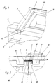
- Fig. 1
- einen perspektivischen Ausschnitt der Geräteoberseite im Bereich der Verbindungsvorrichtung
- Fig. 2
- einen Querschnitt durch die Verbindungsvorrichtung an der Berührungsstelle zweier Großküchengeräte
- Fig. 3
- einen Längsschnitt durch die Verbindungsvorrichtung
- Fig. 4
- eine abgewandelte Form für einen seitlichen Geräteabschluß
- Fig. 5
- eine Ausführung als Arbeits- und Ausgleichsplatte
- Fig. 1
- a perspective section of the top of the device in the area of the connecting device
- Fig. 2
- a cross section through the connecting device at the contact point of two commercial kitchen appliances
- Fig. 3
- a longitudinal section through the connecting device
- Fig. 4
- a modified form for a side device closure
- Fig. 5
- a version as a worktop and compensation plate
Im Bereich des Verbindungselementes 3 ist die Geräteabdeckung entlang der Berührungsseite zweier aneinander stehender Geräte mit einem Wulst 10 versehen. Zwischen dem Wulst 10 und dem Verbindungselement 3 befindet sich eine Dichtung 11, die das Eindringen von Feuchtigkeit o. dgl. verhindert. Der im Querschnitt rechteckförmige Wulst 10 einschließlich Dichtung 11 und Verbindungselement 3 sind so dimensioniert, daß die obere ebene Fläche des Verbindungselementes niveaugleich mit der Geräteabdeckung 5 ist. Es ist so ein optimales Handling durch problemloses Verschieben von Töpfen, Pfannen und Behältern gewährleistet. Der in Fig. 2 angedeutete Topf 12 soll diese verdeutlichen.
Fugenlos eingeprägte U-förmige öffnungen 13 im vorderen Bereich der Geräteabdeckung neben dem Wulst 10 verhindern, daß Kochgut von einem Gerät zum anderen gelangen kann.In the area of the connecting
Seamlessly embossed U-shaped
Je nach Gerätetyp ist die Geräteabdeckung muldenförmig ausgebildet, und überlaufendes Kochgut wird durch ein Ablaufrohr 14 in den Bodenrost geführt.Depending on the type of device, the device cover is trough-shaped, and overflowing cookware is guided through a
Für das linke bzw. rechte Außengerät oder das einzeln stehende Gerät wird ein von der Ausführung her identisches, maßlich aber abweichendes Verbindungselement 15(Fig. 4) vorgesehen.
Fig. 5 deutet an, daß zwei mit Abstand voneinander aufgestellte Geräte 1 und 2 durch eine Arbeitsplatte 16 überbrückt werden können, welche genauso wie das Verbindungselement aufgebaut ist.
Hierdurch entfallen zusätzliche Verbindungselemente.A connecting element 15 (FIG. 4) which is identical in terms of design but differs in size is provided for the left or right outdoor unit or the single standing unit.
Fig. 5 indicates that two
This eliminates additional connecting elements.
Claims (5)
daß die obere Geräteabdeckung entlang der Berührungsseite zweier aneinander zu stehen kommender Geräte (1; 2) mit einem Wulst (10) versehen ist, wobei über die beiden nebeneinander liegenden Wulste (10) zweier GEräte ein Verbindungselement (3) mit U-förmigem und dem Profil der beiden Wulste entsprechend dimensionierten Querschnitt klemmbar ist, welches an der Gerätevorderseite zweimal so abgekantet ist, daß die untere waagerechte Abkantung (4) unter die Geräteabdeckung greift, und daß eine weitere, hintere, nach oben aufgekantete Lasche (6) des Verbindungselementes (3) an der hinteren Abschlußleiste (7) anliegt, gehaltert von einem die Abschlußleiste (7) und die Lasche (6) übergreifenden Abdeckprofil (8).Connecting device for kitchen utensils standing next to one another, the upper device cover of which, on the one hand, projects forward over the device housing and, on the other hand, has a rear, upstanding end strip, characterized in that
that the upper device cover is provided with a bead (10) along the contact side of two devices (1; 2) to be placed against each other, with a connecting element (3) with a U-shaped and that over the two adjacent beads (10) of two devices Profile of the two beads correspondingly dimensioned cross-section can be clamped, which is folded twice on the front of the device so that the lower horizontal bend (4) engages under the device cover, and that a further, rear, upwardly flared tab (6) of the connecting element (3 ) bears against the rear cover strip (7), held by a cover profile (8) which overlaps the cover strip (7) and the tab (6).
zwischen dem Verbindungselement (3) und den Wülsten (10) eine Dichtung (11) angeordnet ist.Connecting device according to claim 1, characterized in that
a seal (11) is arranged between the connecting element (3) and the beads (10).
Applications Claiming Priority (2)
| Application Number | Priority Date | Filing Date | Title |
|---|---|---|---|
| DE4034250A DE4034250A1 (en) | 1990-10-27 | 1990-10-27 | CONNECTING DEVICE FOR SUPPORTING KITCHEN EQUIPMENT |
| DE4034250 | 1990-10-27 |
Publications (2)
| Publication Number | Publication Date |
|---|---|
| EP0483589A1 true EP0483589A1 (en) | 1992-05-06 |
| EP0483589B1 EP0483589B1 (en) | 1995-01-11 |
Family
ID=6417189
Family Applications (1)
| Application Number | Title | Priority Date | Filing Date |
|---|---|---|---|
| EP91117542A Expired - Lifetime EP0483589B1 (en) | 1990-10-27 | 1991-10-14 | Linking device for adjacent kitchen equipment |
Country Status (3)
| Country | Link |
|---|---|
| EP (1) | EP0483589B1 (en) |
| AT (1) | ATE116820T1 (en) |
| DE (2) | DE4034250A1 (en) |
Cited By (7)
| Publication number | Priority date | Publication date | Assignee | Title |
|---|---|---|---|---|
| DE4228076C1 (en) * | 1992-08-24 | 1993-08-05 | Palux Technik Fuer Die Gastronomie Gmbh, 6990 Bad Mergentheim, De | Connecting element for two adjacent,large kitchen units etc. - is adjustable in unit butt joint and has rear hook and front screw coupling |
| FR2694170A1 (en) * | 1992-07-30 | 1994-02-04 | Palux Ag | Joint between cookers and kitchen units in large kitchen - includes bar fixed between two units by hooks at back, and screw having eccentric which engages in vertical oblong hole in front end of bar |
| FR2712071A1 (en) * | 1993-11-08 | 1995-05-12 | Fagor S Coop Ltda | Set of modular commercial cooking appliances |
| WO1998020776A1 (en) * | 1996-11-08 | 1998-05-22 | Lohberger, Heiz + Kochgeräte Gesellschaft M.B.H. | Kitchen arrangement with a top part and at least one substructure, carriage for removably suspending a substructure module from the top part |
| ES2127054A1 (en) * | 1995-05-08 | 1999-04-01 | Fagor S Coop | Cooker (stove) with suspended commercial modules |
| US6899404B1 (en) * | 2003-06-16 | 2005-05-31 | Ron E. King | Cabinet system |
| DE102011115109A1 (en) * | 2011-10-07 | 2013-04-11 | Claudia Musch | Mobile kitchen device for use in e.g. kitchen region, has box elements with upper side comprising carrier plate for devices and/or units, where carrier plate is not anchored with box elements and is connected with box elements |
Families Citing this family (2)
| Publication number | Priority date | Publication date | Assignee | Title |
|---|---|---|---|---|
| DE102004009606B4 (en) | 2004-02-27 | 2018-03-29 | BSH Hausgeräte GmbH | field of work |
| CN109090859B (en) * | 2018-09-14 | 2020-05-12 | 吴嘉馨 | Seamless mounting assembly for integrated cooker |
Citations (4)
| Publication number | Priority date | Publication date | Assignee | Title |
|---|---|---|---|---|
| US2778032A (en) * | 1952-09-22 | 1957-01-22 | William J Meehan | Self-locking sink frame |
| US2789874A (en) * | 1955-05-11 | 1957-04-23 | United Metal Cabinet Corp | Counter-top brace and trim construction |
| EP0093823A1 (en) * | 1982-04-23 | 1983-11-16 | Ditta Angelo Po Grandi Impianti Spa | Improvements in the cooking modular equipments for large kitchen plants |
| EP0271388A1 (en) * | 1986-11-19 | 1988-06-15 | Société Anonyme des USINES DE ROSIERES | Closely assembled modular cooking appliance |
-
1990
- 1990-10-27 DE DE4034250A patent/DE4034250A1/en not_active Withdrawn
-
1991
- 1991-10-14 AT AT91117542T patent/ATE116820T1/en not_active IP Right Cessation
- 1991-10-14 EP EP91117542A patent/EP0483589B1/en not_active Expired - Lifetime
- 1991-10-14 DE DE59104236T patent/DE59104236D1/en not_active Expired - Fee Related
Patent Citations (4)
| Publication number | Priority date | Publication date | Assignee | Title |
|---|---|---|---|---|
| US2778032A (en) * | 1952-09-22 | 1957-01-22 | William J Meehan | Self-locking sink frame |
| US2789874A (en) * | 1955-05-11 | 1957-04-23 | United Metal Cabinet Corp | Counter-top brace and trim construction |
| EP0093823A1 (en) * | 1982-04-23 | 1983-11-16 | Ditta Angelo Po Grandi Impianti Spa | Improvements in the cooking modular equipments for large kitchen plants |
| EP0271388A1 (en) * | 1986-11-19 | 1988-06-15 | Société Anonyme des USINES DE ROSIERES | Closely assembled modular cooking appliance |
Cited By (9)
| Publication number | Priority date | Publication date | Assignee | Title |
|---|---|---|---|---|
| FR2694170A1 (en) * | 1992-07-30 | 1994-02-04 | Palux Ag | Joint between cookers and kitchen units in large kitchen - includes bar fixed between two units by hooks at back, and screw having eccentric which engages in vertical oblong hole in front end of bar |
| DE4228076C1 (en) * | 1992-08-24 | 1993-08-05 | Palux Technik Fuer Die Gastronomie Gmbh, 6990 Bad Mergentheim, De | Connecting element for two adjacent,large kitchen units etc. - is adjustable in unit butt joint and has rear hook and front screw coupling |
| FR2712071A1 (en) * | 1993-11-08 | 1995-05-12 | Fagor S Coop Ltda | Set of modular commercial cooking appliances |
| ES2078160A2 (en) * | 1993-11-08 | 1995-12-01 | Fagor S Coop Ltda | Set of modular commercial cooking appliances |
| ES2127054A1 (en) * | 1995-05-08 | 1999-04-01 | Fagor S Coop | Cooker (stove) with suspended commercial modules |
| WO1998020776A1 (en) * | 1996-11-08 | 1998-05-22 | Lohberger, Heiz + Kochgeräte Gesellschaft M.B.H. | Kitchen arrangement with a top part and at least one substructure, carriage for removably suspending a substructure module from the top part |
| US6899404B1 (en) * | 2003-06-16 | 2005-05-31 | Ron E. King | Cabinet system |
| DE102011115109A1 (en) * | 2011-10-07 | 2013-04-11 | Claudia Musch | Mobile kitchen device for use in e.g. kitchen region, has box elements with upper side comprising carrier plate for devices and/or units, where carrier plate is not anchored with box elements and is connected with box elements |
| DE102011115109B4 (en) * | 2011-10-07 | 2016-09-01 | Claudia Musch | Mobile kitchen device |
Also Published As
| Publication number | Publication date |
|---|---|
| DE59104236D1 (en) | 1995-02-23 |
| DE4034250A1 (en) | 1992-04-30 |
| EP0483589B1 (en) | 1995-01-11 |
| ATE116820T1 (en) | 1995-01-15 |
Similar Documents
| Publication | Publication Date | Title |
|---|---|---|
| DE4210010C2 (en) | Cooktop | |
| EP0483589B1 (en) | Linking device for adjacent kitchen equipment | |
| DE3907204C2 (en) | Device for mounting a bath mixer | |
| DE102004009606B4 (en) | field of work | |
| DE3120989C2 (en) | Kitchen insertion device | |
| EP0567779B1 (en) | Cooking plate | |
| EP0441363B1 (en) | Flush-mounted apparatus with cover strip | |
| DE8901613U1 (en) | Connecting element for front-facing installation ducts | |
| DE9001977U1 (en) | Cover for covering parts | |
| DE1590188C3 (en) | Dashboard for the arrangement of plugs or the like. for work tables | |
| EP0517159B1 (en) | Arrangement of a front panel for a household appliance, in particular for a dishwasher | |
| EP0541849A1 (en) | Connection of surfaces, and washing and/or drying machine | |
| DE10210754B4 (en) | Control cabinet with a frame and a cable entry in the top wall | |
| EP0803684A2 (en) | Multiple-plate radiator | |
| DE7530601U (en) | BRACKET FOR A WALL CABINET | |
| DE102013204143A1 (en) | Filter unit for extractor hood and extractor hood | |
| EP0532827A1 (en) | Shower cabinet | |
| DE9301942U1 (en) | Built-in hob | |
| EP0052267A1 (en) | Lighting fixture under a kitchen wall-cabinet | |
| EP0614053B1 (en) | Installation and mounting of large scale kitchens | |
| EP1023859A2 (en) | Support plate for furniture element | |
| DE4306545C1 (en) | Kitchen with adjacent interconnected work units - has grease collector channel at connecting point, fitting into gap formed by angled top edges | |
| DE8010311U1 (en) | COVER GRID FOR RADIATOR | |
| EP4434398A1 (en) | Cupboard with illuminated recessed grip between two fronts | |
| DE8407125U1 (en) | BASE FOR BUILT-IN FURNITURE |
Legal Events
| Date | Code | Title | Description |
|---|---|---|---|
| PUAI | Public reference made under article 153(3) epc to a published international application that has entered the european phase |
Free format text: ORIGINAL CODE: 0009012 |
|
| AK | Designated contracting states |
Kind code of ref document: A1 Designated state(s): AT BE CH DE FR IT LI NL SE |
|
| 17P | Request for examination filed |
Effective date: 19920527 |
|
| 17Q | First examination report despatched |
Effective date: 19940325 |
|
| GRAA | (expected) grant |
Free format text: ORIGINAL CODE: 0009210 |
|
| AK | Designated contracting states |
Kind code of ref document: B1 Designated state(s): AT BE CH DE FR IT LI NL SE |
|
| REF | Corresponds to: |
Ref document number: 116820 Country of ref document: AT Date of ref document: 19950115 Kind code of ref document: T |
|
| EAL | Se: european patent in force in sweden |
Ref document number: 91117542.0 |
|
| REF | Corresponds to: |
Ref document number: 59104236 Country of ref document: DE Date of ref document: 19950223 |
|
| ET | Fr: translation filed | ||
| ITF | It: translation for a ep patent filed | ||
| PLBE | No opposition filed within time limit |
Free format text: ORIGINAL CODE: 0009261 |
|
| STAA | Information on the status of an ep patent application or granted ep patent |
Free format text: STATUS: NO OPPOSITION FILED WITHIN TIME LIMIT |
|
| 26N | No opposition filed | ||
| PGFP | Annual fee paid to national office [announced via postgrant information from national office to epo] |
Ref country code: FR Payment date: 19991018 Year of fee payment: 9 |
|
| PGFP | Annual fee paid to national office [announced via postgrant information from national office to epo] |
Ref country code: SE Payment date: 19991021 Year of fee payment: 9 Ref country code: AT Payment date: 19991021 Year of fee payment: 9 |
|
| PGFP | Annual fee paid to national office [announced via postgrant information from national office to epo] |
Ref country code: BE Payment date: 19991022 Year of fee payment: 9 |
|
| PGFP | Annual fee paid to national office [announced via postgrant information from national office to epo] |
Ref country code: NL Payment date: 19991027 Year of fee payment: 9 |
|
| PG25 | Lapsed in a contracting state [announced via postgrant information from national office to epo] |
Ref country code: AT Free format text: LAPSE BECAUSE OF NON-PAYMENT OF DUE FEES Effective date: 20001014 |
|
| PGFP | Annual fee paid to national office [announced via postgrant information from national office to epo] |
Ref country code: CH Payment date: 20001023 Year of fee payment: 10 |
|
| PG25 | Lapsed in a contracting state [announced via postgrant information from national office to epo] |
Ref country code: SE Free format text: THE PATENT HAS BEEN ANNULLED BY A DECISION OF A NATIONAL AUTHORITY Effective date: 20001030 |
|
| PG25 | Lapsed in a contracting state [announced via postgrant information from national office to epo] |
Ref country code: BE Free format text: LAPSE BECAUSE OF NON-PAYMENT OF DUE FEES Effective date: 20001031 |
|
| PGFP | Annual fee paid to national office [announced via postgrant information from national office to epo] |
Ref country code: DE Payment date: 20001227 Year of fee payment: 10 |
|
| BERE | Be: lapsed |
Owner name: JUNO GROSSKUCHEN G.M.B.H. Effective date: 20001031 |
|
| PG25 | Lapsed in a contracting state [announced via postgrant information from national office to epo] |
Ref country code: NL Free format text: LAPSE BECAUSE OF NON-PAYMENT OF DUE FEES Effective date: 20010501 |
|
| EUG | Se: european patent has lapsed |
Ref document number: 91117542.0 |
|
| PG25 | Lapsed in a contracting state [announced via postgrant information from national office to epo] |
Ref country code: FR Free format text: LAPSE BECAUSE OF NON-PAYMENT OF DUE FEES Effective date: 20010629 |
|
| NLV4 | Nl: lapsed or anulled due to non-payment of the annual fee |
Effective date: 20010501 |
|
| REG | Reference to a national code |
Ref country code: FR Ref legal event code: ST |
|
| PG25 | Lapsed in a contracting state [announced via postgrant information from national office to epo] |
Ref country code: LI Free format text: LAPSE BECAUSE OF NON-PAYMENT OF DUE FEES Effective date: 20011031 Ref country code: CH Free format text: LAPSE BECAUSE OF NON-PAYMENT OF DUE FEES Effective date: 20011031 |
|
| REG | Reference to a national code |
Ref country code: CH Ref legal event code: PL |
|
| PG25 | Lapsed in a contracting state [announced via postgrant information from national office to epo] |
Ref country code: DE Free format text: LAPSE BECAUSE OF NON-PAYMENT OF DUE FEES Effective date: 20020702 |
|
| PG25 | Lapsed in a contracting state [announced via postgrant information from national office to epo] |
Ref country code: IT Free format text: LAPSE BECAUSE OF NON-PAYMENT OF DUE FEES;WARNING: LAPSES OF ITALIAN PATENTS WITH EFFECTIVE DATE BEFORE 2007 MAY HAVE OCCURRED AT ANY TIME BEFORE 2007. THE CORRECT EFFECTIVE DATE MAY BE DIFFERENT FROM THE ONE RECORDED. Effective date: 20051014 |