EP0803684A2 - Multiple-plate radiator - Google Patents
Multiple-plate radiator Download PDFInfo
- Publication number
- EP0803684A2 EP0803684A2 EP97106672A EP97106672A EP0803684A2 EP 0803684 A2 EP0803684 A2 EP 0803684A2 EP 97106672 A EP97106672 A EP 97106672A EP 97106672 A EP97106672 A EP 97106672A EP 0803684 A2 EP0803684 A2 EP 0803684A2
- Authority
- EP
- European Patent Office
- Prior art keywords
- side cover
- grille
- cover
- cover part
- tabs
- Prior art date
- Legal status (The legal status is an assumption and is not a legal conclusion. Google has not performed a legal analysis and makes no representation as to the accuracy of the status listed.)
- Withdrawn
Links
Images

Classifications
-
- F—MECHANICAL ENGINEERING; LIGHTING; HEATING; WEAPONS; BLASTING
- F24—HEATING; RANGES; VENTILATING
- F24D—DOMESTIC- OR SPACE-HEATING SYSTEMS, e.g. CENTRAL HEATING SYSTEMS; DOMESTIC HOT-WATER SUPPLY SYSTEMS; ELEMENTS OR COMPONENTS THEREFOR
- F24D19/00—Details
- F24D19/06—Casings, cover lids or ornamental panels, for radiators
- F24D19/065—Grids attached to the radiator and covering its top
-
- F—MECHANICAL ENGINEERING; LIGHTING; HEATING; WEAPONS; BLASTING
- F24—HEATING; RANGES; VENTILATING
- F24D—DOMESTIC- OR SPACE-HEATING SYSTEMS, e.g. CENTRAL HEATING SYSTEMS; DOMESTIC HOT-WATER SUPPLY SYSTEMS; ELEMENTS OR COMPONENTS THEREFOR
- F24D19/00—Details
- F24D19/06—Casings, cover lids or ornamental panels, for radiators
Definitions
- the invention relates to a multi-panel radiator, in which the spaced radiator panels are connected in the upper and lower area by T-shaped connecting pieces and side panels are held in the lower area on a corresponding connecting piece for lateral covering of the plate space, with the circumferential, downwardly angled rectangular
- the side cover parts are held on the edge of the cover grid.
- Such a panel for a multi-panel radiator is known from DE-GM 295 05 238.
- two pairs, each with two spaced tabs or edge sections, are provided on the front edges of the cover grid, a hooking element being formed on one tab, which engages in an opening in an inwardly offset section on the side cover part to achieve a non-releasable connection.
- one tab of a pair on the front edge of the cover grid is offset by the thickness of the section on the side cover part set back inwards.
- the hooking of the side cover parts with the cover grid in the vertical direction means that the connection cannot be released independently. The connection is thus secured even after installation on the radiator during transport and treatment on construction sites.
- the object of the invention is to propose, for a multi-panel radiator, an easy-to-install cladding system which is as flush as possible on the outside, consisting of a cover grille and two side cover parts.
- the object of the invention is achieved on a multi-panel radiator with the features of claim 1.
- the cranked tabs formed on the face of the side cover parts can be inserted into the corresponding slots on the front edges of the cover part for assembly. Then the side cover parts are folded down into a vertical position. In this position, the side cover part is secured by screw connections known per se in the lower region on a T-shaped connecting piece of the multi-plate heating element.
- two of the recessed areas are provided on a front edge of the cover grid at a distance from one another, into which two associated tabs on the side cover parts are inserted.
- Such side cover parts assembled according to the invention can be removed from the cover grille again after removal of a screw lock.
- the laterally folded side cover part 1 has on its upper end face 13 two inwardly bent tabs 14 which are arranged at a distance from one another in the outer edge region.
- An approximately U-shaped rounded incision 12, 11 is provided in the middle in each case below and above as access to the T-shaped connecting pieces 4, 5 of a multi-plate heating element (not shown in more detail).
- the sections of the tabs 14 which are visible from the outside after the connection are recessed in the recessed area 211 and are flush with their outer surface to the outer surface of the end face edge 21.
- the connecting piece of a T-shaped connecting piece of the radiator indicated in the area of the upper incision with the number 4 is the connecting piece of a T-shaped connecting piece of the radiator indicated.
- the side cover part 1 With the lower incision 12, the side cover part 1 is pivoted over the connection piece of the lower T-shaped connecting piece indicated by the number 5.
- the side cover part 1 is secured with a screw connection that can only be removed with tools, of which the plastic sleeve 3, which lies with its collar on the outside, can be seen in FIG. 1.
- Such a screw connection is known for example from DE-GM 90 14 178.
- the free end leg 142 of these cranked tabs 14 is inclined slightly to the plane of the side cover part with respect to the vertical.
Landscapes
- Engineering & Computer Science (AREA)
- Physics & Mathematics (AREA)
- Thermal Sciences (AREA)
- Chemical & Material Sciences (AREA)
- Combustion & Propulsion (AREA)
- Mechanical Engineering (AREA)
- General Engineering & Computer Science (AREA)
- Domestic Hot-Water Supply Systems And Details Of Heating Systems (AREA)
- Air-Flow Control Members (AREA)
- Cooling Or The Like Of Electrical Apparatus (AREA)
Abstract
Ein Mehrplattenheizkörper weist auf Abstand gehaltene Heizkörperplatten auf, die im oberen und unteren Bereich durch T-förmige Anschlußstücke verbunden sind. Zur seitlichen Abdeckung des Plattenzwischenraumes sind Seitenabdeckteile 1 und zur oberseitigen Abdeckung des Plattenzwischenraumes ein Abdeckgitter 2 vorgesehen. Das Abdeckgitter 2 ist umlaufend abgekantet ausgebildet, wobei die Seitenabdeckteile 1 an den Stirnseiten des Abdeckgitters 2 gehalten sind. Zum Halten der Seitenabdeckteile 1 sind den stirnseitigen Abkantungen des Abdeckgitters 2 um mindestens die Blechmaterialstärke zurückversetzte, nach unten durchlaufende Bereiche 211 vorgesehen, in die jeweils ein zur Gitterebene paralleler Schlitz 212 eingebracht ist. Ein Seitenabdeckteil 1 umfaßt in seinem oberen Bereich etwa Z-förmig zur Heizkörperseite hin verkröpfte Laschen 14, mit denen ein Seitenabdeckteil 1 in die Schlitze 212 der Bereiche 211 einhakbar ist.
Description
Die Erfindung betrifft einen Mehrplattenheizkörper, bei dem die auf Abstand gehaltenen Heizkörperplatten im oberen und unteren Bereich durch T-förmige Anschlußstücke verbunden und zur seitlichen Abdeckung des Plattenzwischenraumes Seitenteile im unteren Bereich an einem entsprechenden Anschlußstück gehalten sind, wobei an dem umlaufenden, nach unten abgewinkelten rechteckigen Rand des Abdeckgitters stirnseitig die Seitenabdeckteile gehalten sind.The invention relates to a multi-panel radiator, in which the spaced radiator panels are connected in the upper and lower area by T-shaped connecting pieces and side panels are held in the lower area on a corresponding connecting piece for lateral covering of the plate space, with the circumferential, downwardly angled rectangular The side cover parts are held on the edge of the cover grid.
Eine solche Verkleidung für einen Mehrplattenheizkörper ist aus dem DE-GM 295 05 238 bekannt. Dabei sind an den stirnseitigen Rändern des Abdeckgitters zwei Paare mit jeweils zwei beabstandeten Laschen oder Randabschnitten vorgesehen, wobei an einer Lasche ein Verhakungselement ausgebildet ist, welches zur Erzielung einer nicht lösbaren Verbindung in einen Durchbruch in einem nach innen versetzten Abschnitt am Seitenabdeckteil eingreift. Jeweils eine Lasche eines Paares an dem Stirnrand des Abdeckgitters ist dabei um die Stärke des nach innen zurückversetzten Abschnittes am Seitenabdeckteil versetzt. Durch die Verhakung der Seitenabdeckteile mit dem Abdeckgitter in senkrechter Richtung ist ein selbständiges Lösen der Verbindung nicht möglich. Die Verbindung ist damit auch nach der Montage am Heizkörper während des Transportes und der Behandlung auf Baustellen gesichert.Such a panel for a multi-panel radiator is known from DE-GM 295 05 238. In this case, two pairs, each with two spaced tabs or edge sections, are provided on the front edges of the cover grid, a hooking element being formed on one tab, which engages in an opening in an inwardly offset section on the side cover part to achieve a non-releasable connection. In each case one tab of a pair on the front edge of the cover grid is offset by the thickness of the section on the side cover part set back inwards. The hooking of the side cover parts with the cover grid in the vertical direction means that the connection cannot be released independently. The connection is thus secured even after installation on the radiator during transport and treatment on construction sites.
Eine solche Konstruktion erfordert die relativ exakte vertikale Montage des Seitenabdeckteiles zum Abdeckgitter. Am Heizkörper selbst läßt sich nur die Einheit aus Abdeckgitter und den daran unlösbar festgesetzten Seitenabdeckteilen von oben vornehmen. Ein nachträgliches Ansetzen eines Seitenabdeckteiles an einem bereits vorher auf dem Heizkörper aufgesetzten Abdeckgitter ist nicht möglich.Such a construction requires the relatively exact vertical mounting of the side cover part to the grille. On the radiator itself, only the unit consisting of the grille and the side cover parts that are permanently attached to it can be made from above. Subsequent attachment of a side cover part to a cover grid already placed on the radiator is not possible.
Die Aufgabe der Erfindung besteht darin, für einen Mehrplattenheizkörper ein einfach zu montierendes und dabei möglichst außen flächenbündiges Verkleidungssystem, bestehend aus einem Abdeckgitter und zwei Seitenabdeckteilen, vorzuschlagen.The object of the invention is to propose, for a multi-panel radiator, an easy-to-install cladding system which is as flush as possible on the outside, consisting of a cover grille and two side cover parts.
Gelöst wird die Erfindungsaufgabe an einem Mehrplattenheizkörper mit den Merkmalen des Anspruchs 1.The object of the invention is achieved on a multi-panel radiator with the features of
Zur Montage können bei einer solchen Abdeckung die an den Seitenabdeckteilen stirnseitig angeformten verkröpften Laschen in die entsprechenden Schlitze an den Stirnrändern des Abdeckteiles eingesteckt werden. Danach erfolgt das Abklappen der Seitenabdeckteile in eine vertikale Position. In dieser Position wird das Seitenabdeckteil durch an sich bekannte Verschraubungen im unteren Bereich an einem T-förmigen Anschlußstück des Mehrplattenheizkörpers gesichert.With such a cover, the cranked tabs formed on the face of the side cover parts can be inserted into the corresponding slots on the front edges of the cover part for assembly. Then the side cover parts are folded down into a vertical position. In this position, the side cover part is secured by screw connections known per se in the lower region on a T-shaped connecting piece of the multi-plate heating element.
Nach einer bevorzugten Ausführungsart der Erfindung sind jeweils gemäß Anspruch 2 an einem stirnseitigen Rand des Abdeckgitters mit Abstand voneinander zwei der zurückversetzten Bereiche vorgesehen, in die zwei zugehörige Laschen an den Seitenabdeckteilen eingeführt sind.According to a preferred embodiment of the invention, two of the recessed areas are provided on a front edge of the cover grid at a distance from one another, into which two associated tabs on the side cover parts are inserted.
Solche erfindungsgemäß montierten Seitenabdeckteile lassen sich nach Abnahme einer Verschraubungssicherung wieder vom Abdeckgitter abnehmen.Such side cover parts assembled according to the invention can be removed from the cover grille again after removal of a screw lock.
Anhand eines abgebildeten Ausführungsbeispieles wird die Erfindung im folgenden näher erläutert. Es zeigen:
- Fig. 1
- die Ansicht auf ein Seitenabdeckteil, welches im oberen Stirnbereich mit dem Abdeckgitter verbunden ist,
- Fig. 2
- eine vergrößerte Schnittdarstellung nach der Linie I-I in
Figur 2 und - Fig. 3
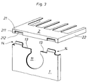
- eine perspektivische Darstellung der Montagesituation eines Seitenabdeckteiles an dem zugehörigen Abdeckgitter.
- Fig. 1
- the view of a side cover part which is connected to the grille in the upper end region,
- Fig. 2
- an enlarged sectional view along the line II in Figure 2 and
- Fig. 3
- a perspective view of the mounting situation of a side cover on the associated grille.
Wie aus Figur 3 ersichtlich, weist das seitlich abgekantete Seitenabdeckteil 1 an seiner oberen Stirnseite 13 zwei nach innen verkröpfte Laschen 14 auf, die mit Abstand voneinander im äußeren Randbereich angeordnet sind. Mittig ist jeweils unten und oben ein etwa U-förmiger abgerundeter Einschnitt 12, 11 vorgesehen als Zugang zu den T-förmigen Anschlußstücken 4, 5 eines nicht näher dargestellten Mehrplattenheizkörpers.As can be seen from FIG. 3, the laterally folded
Zur Verbindung mit den beiden Laschen 14 des Seitenabdeckteiles 1 sind in entsprechender Anordnung an den Stirnseitenrändern 21 des Abdeckgitters 2, die einen seitlichen Rand 22 aufweisen, um etwa die Blechstärke zurückversetzte Bereiche 211 vorgesehen, in denen jeweils ein horizontaler Schlitz 212 angeordnet ist.For connection to the two
In einer Schrägstellung zum Abdeckgitter 2 wird das Seitenabdeckteil 1 mit seinen verkröpften Laschen 14 durch diese Schlitze 212 hindurchgeführt. Beim Abschwenken in die vertikale Position gelangen Schenkel 142 und Verkröpfung 141 von innen hinter den Stirnseitenrand 21 des Abdeckgitters 2. Die Verkröpfung 141 setzt in dieser Position auf den zurückversetzten Bereich des Stirnseitenrandes 21 auf, wie aus Figur 2 ersichtlich.In an inclined position relative to the
Die nach der Verbindung von außen sichtbaren Abschnitte der Laschen 14 liegen versenkt in dem zurückversetzten Bereich 211 und liegen dabei bündig mit ihrer Außenfläche zur Außenfläche des Stirnseitenrandes 21. Im Bereich des oberen Einschnittes ist mit der Ziffer 4 der Anschlußstutzen eines T-förmigen Anschlußstückes des Heizkörpers angedeutet. Mit dem unteren Einschnitt 12 ist das Seitenabdeckteil 1 über den mit der Ziffer 5 angedeuteten Anschlußstutzen des unteren T-förmigen Anschlußstückes aufgeschwenkt. An diesem Anschlußstück bzw. an dem Anschlußstutzen 5 ist das Seitenabdeckteil 1 mit einer nur mit Werkzeugen lösbaren Verschraubung gesichert, von der die mit ihrem Bund außen anliegende Kunststoffhülse 3 in Figur 1 erkennbar ist. Eine solche Verschraubung ist beispielsweise aus dem DE-GM 90 14 178 bekannt.The sections of the
Um der Verbindung zwischen Seitenabdeckteil bzw. deren Laschen 14 und dem Abdeckgitter eine gewisse Vorspannung zu verleihen, ist jeweils der freie Endschenkel 142 dieser verkröpften Laschen 14 geringfügig zur Ebene des Seitenabdeckteiles gegenüber der Vertikalen geneigt.In order to give the connection between the side cover part or its
- 11
- SeitenabdeckteilSide cover part
- 1111
- AusnehmungRecess
- 1212th
- AusnehmungRecess
- 1313
- StirnseiteFace
- 1414
- LascheTab
- 141141
- VerkröpfungCranking
- 142142
- Schenkelleg
- 22nd
- AbdeckgitterCover grille
- 2121
- StirnseitenrandFront margin
- 211211
- zurückversetzter Bereichset back area
- 212212
- Schlitzslot
- 2222
- LängsseitenrandLong edge
- 33rd
- KunststoffhülsePlastic sleeve
- 44th
- AnschlußstutzenConnecting piece
- 55
- AnschlußstutzenConnecting piece
Claims (6)
Applications Claiming Priority (2)
| Application Number | Priority Date | Filing Date | Title |
|---|---|---|---|
| DE29607615U DE29607615U1 (en) | 1996-04-26 | 1996-04-26 | Multi-panel radiator |
| DE29607615U | 1996-04-26 |
Publications (2)
| Publication Number | Publication Date |
|---|---|
| EP0803684A2 true EP0803684A2 (en) | 1997-10-29 |
| EP0803684A3 EP0803684A3 (en) | 1998-10-21 |
Family
ID=8023197
Family Applications (1)
| Application Number | Title | Priority Date | Filing Date |
|---|---|---|---|
| EP97106672A Withdrawn EP0803684A3 (en) | 1996-04-26 | 1997-04-22 | Multiple-plate radiator |
Country Status (2)
| Country | Link |
|---|---|
| EP (1) | EP0803684A3 (en) |
| DE (1) | DE29607615U1 (en) |
Cited By (3)
| Publication number | Priority date | Publication date | Assignee | Title |
|---|---|---|---|---|
| DE19851207A1 (en) * | 1998-11-06 | 2000-05-18 | Wiemann Gmbh | Cladding for flat radiator has top covering grid plate with downward bent edges , sides, and two connecting elements, openings for plug-in element |
| EP0931987A3 (en) * | 1998-01-23 | 2001-11-21 | Caradon Heating Europe B.V. | Covering for radiators |
| EP0974791A3 (en) * | 1998-07-22 | 2002-05-02 | Wiemann GmbH | Cover for plate radiator with outside actuator |
Families Citing this family (2)
| Publication number | Priority date | Publication date | Assignee | Title |
|---|---|---|---|---|
| DE19805861C1 (en) * | 1998-02-13 | 1999-04-08 | Wiemann Gmbh | Cover for building heating radiator |
| DE102004037438A1 (en) * | 2004-07-30 | 2006-03-23 | Wiemann Gmbh | Plug-in cover of a radiator |
Family Cites Families (4)
| Publication number | Priority date | Publication date | Assignee | Title |
|---|---|---|---|---|
| US2512662A (en) * | 1947-06-11 | 1950-06-27 | Marver Metal Mfg Co | Furniture |
| DE9007630U1 (en) * | 1989-03-10 | 1993-06-24 | Kermi GmbH, 8350 Plattling | Radiator cover |
| DE9014178U1 (en) * | 1990-10-12 | 1990-12-20 | Fa. Wolfgang Förster, 5870 Hemer | Multi-panel radiators |
| DE29505238U1 (en) * | 1995-03-28 | 1995-06-01 | Paul Edelhoff KG, 58638 Iserlohn | Panel for a panel radiator |
-
1996
- 1996-04-26 DE DE29607615U patent/DE29607615U1/en not_active Expired - Lifetime
-
1997
- 1997-04-22 EP EP97106672A patent/EP0803684A3/en not_active Withdrawn
Cited By (4)
| Publication number | Priority date | Publication date | Assignee | Title |
|---|---|---|---|---|
| EP0931987A3 (en) * | 1998-01-23 | 2001-11-21 | Caradon Heating Europe B.V. | Covering for radiators |
| CZ298344B6 (en) * | 1998-01-23 | 2007-09-05 | Caradon Heating Europe B. V. | Radiator cover |
| EP0974791A3 (en) * | 1998-07-22 | 2002-05-02 | Wiemann GmbH | Cover for plate radiator with outside actuator |
| DE19851207A1 (en) * | 1998-11-06 | 2000-05-18 | Wiemann Gmbh | Cladding for flat radiator has top covering grid plate with downward bent edges , sides, and two connecting elements, openings for plug-in element |
Also Published As
| Publication number | Publication date |
|---|---|
| DE29607615U1 (en) | 1996-07-11 |
| EP0803684A3 (en) | 1998-10-21 |
Similar Documents
| Publication | Publication Date | Title |
|---|---|---|
| DE2446080C2 (en) | Partition system with a first and a second partition element and a connecting part | |
| DE4210010A1 (en) | COOKING HOB | |
| AT409069B (en) | drawer | |
| DE2725024A1 (en) | WINDOW UNIT FOR OVEN DOOR | |
| EP2467649B1 (en) | Extractor hood | |
| EP1088577B1 (en) | Dividing wall for columns | |
| EP0803684A2 (en) | Multiple-plate radiator | |
| EP0085355B2 (en) | Device for the connection of air-channel elements provided with flange sections at their edges which form openings for corner angles | |
| EP0386496B1 (en) | Radiator cover | |
| EP3973818A1 (en) | Drawer side wall | |
| DE102010023522B4 (en) | Protective grating, in particular leaf trap grille, for a motor vehicle | |
| EP0541849A1 (en) | Connection of surfaces, and washing and/or drying machine | |
| DE7902216U1 (en) | Equipment cabinet | |
| DE8912436U1 (en) | Cover for a panel radiator | |
| EP0735327A2 (en) | Cover for a panel radiator | |
| EP1164893B1 (en) | Mechanical link between the side walls and rear wall of a sheet casing | |
| DE1619719A1 (en) | Bell for the bottom of washing, distillation or rectification columns | |
| DE1530862A1 (en) | Carrier to be placed on the roof of a vehicle | |
| DE3520640A1 (en) | Covering for walls, breasts or the like | |
| DE1505278A1 (en) | Ventilation device for motor vehicle bodies | |
| DE9301942U1 (en) | Built-in hob | |
| EP0077440B1 (en) | Telescoping covers for machine tools | |
| DE9411068U1 (en) | Source outlet | |
| DE9317293U1 (en) | Burner rod | |
| AT410590B (en) | Water heater comprises a housing having side walls and a base interspersed with pipes covered by an apron |
Legal Events
| Date | Code | Title | Description |
|---|---|---|---|
| PUAI | Public reference made under article 153(3) epc to a published international application that has entered the european phase |
Free format text: ORIGINAL CODE: 0009012 |
|
| AK | Designated contracting states |
Kind code of ref document: A2 Designated state(s): AT BE DE FR GB IE IT NL |
|
| PUAL | Search report despatched |
Free format text: ORIGINAL CODE: 0009013 |
|
| AK | Designated contracting states |
Kind code of ref document: A3 Designated state(s): AT BE DE FR GB IE IT NL |
|
| STAA | Information on the status of an ep patent application or granted ep patent |
Free format text: STATUS: THE APPLICATION HAS BEEN WITHDRAWN |
|
| 18W | Application withdrawn |
Withdrawal date: 19990317 |
|
| R18W | Application withdrawn (corrected) |
Effective date: 19990316 |