EP0483093B1 - Reel-up and method for regulation of the nip pressure in a reel-up - Google Patents
Reel-up and method for regulation of the nip pressure in a reel-up Download PDFInfo
- Publication number
- EP0483093B1 EP0483093B1 EP19910850261 EP91850261A EP0483093B1 EP 0483093 B1 EP0483093 B1 EP 0483093B1 EP 19910850261 EP19910850261 EP 19910850261 EP 91850261 A EP91850261 A EP 91850261A EP 0483093 B1 EP0483093 B1 EP 0483093B1
- Authority
- EP
- European Patent Office
- Prior art keywords
- reeling
- revolving roll
- nip
- reel
- roll
- Prior art date
- Legal status (The legal status is an assumption and is not a legal conclusion. Google has not performed a legal analysis and makes no representation as to the accuracy of the status listed.)
- Expired - Lifetime
Links
Images


Classifications
-
- B—PERFORMING OPERATIONS; TRANSPORTING
- B65—CONVEYING; PACKING; STORING; HANDLING THIN OR FILAMENTARY MATERIAL
- B65H—HANDLING THIN OR FILAMENTARY MATERIAL, e.g. SHEETS, WEBS, CABLES
- B65H18/00—Winding webs
- B65H18/08—Web-winding mechanisms
- B65H18/26—Mechanisms for controlling contact pressure on winding-web package, e.g. for regulating the quantity of air between web layers
Definitions
- the invention concerns a reel-up, comprising a first revolving roll and a second revolving roll, which form a nip, into which nip the web is introduced and in which nip a nip pressure acts upon the web and after which nip the web is reeled onto said second revolving roll, which said second revolving roll is supported on reeling rails or equivalent.
- the invention also concerns a method for regulation of the nip pressure in a reel-up, which comprises a first revolving roll and a second revolving roll, which form a nip, into which nip the web is introduced and in which nip a nip pressure acts upon the web and after which nip the web is reeled onto said second revolving roll, which said second revolving roll is supported on reeling rails or equivalent.
- US-A-2 528 713 discloses a method and apparatus where the nip pressure between the paper roll and the reeling cylinder is regulated by adjusting the inclination of rails which slideably support the paper roll.
- the nip pressure should be adjusted for varying weights of paper and it may also be adjusted when it increases with increased size and weight of the paper roll.
- Another method of controlling the nip pressure and obtaining a substantially smooth load distribution is described in GB-A-2 168 040.
- the method in this document seeks to solve the problem of the sudden peak in nip pressure that occurs when moving the paper roll from the primary support forks to secondary support forks and also remedy the problem with uneven hardness distribution, i.e. variation of the radial density in the paper reel. This is achieved by providing loading cylinders acting on the ends of the reeling drum.
- the object of the present invention is to provide a reel-up in which the problems mentioned above do not occur. It is a particular object of the invention to provide a reel-up in which the nip load between the reeling drum and the reeling cylinder is uniform. A further object of the invention is to provide a reel-up in which points of discontinuity that produce broke in the reel bottom do not occur.
- the reel-up in accordance with the invention is mainly characterized in that, for the purpose of regulation of said nip pressure, the reel-up comprises members for alteration of the positions of the first revolving roll and the second revolving roll in relation to one another.
- the method in accordance with the invention is mainly characterized in that, in the method, the positions of the first revolving roll and the second revolving roll in the reel-up in relation to one another are changed and/or additional forces are applied to the ends of the second revolving roll in a direction perpendicular to the direction of the axis of the roll.
- the linear load can be made uniform in the transverse direction of the machine by placing the reeling drum on support in relation to the reeling cylinder so that the force component of the force of gravity of the earth that passes through the centre points of the reeling drum and the reeling cylinder forms the force that is needed for the linear load or nip load.
- the linear load is adjusted by altering the position of the reeling drum in relation to the reeling cylinder, and in this way, at the same time, the magnitude of the force component that produces the linear load is altered.
- a suitable linear load or nip load is produced by means of the own weight of the reeling drum and of the web reeled onto said drum.
- the reeling of the web onto the reeling drum is started against the reeling cylinder at a point at which the force component of the force of gravity of the earth applied to the reeling drum that is directed at the centre point of the reeling cylinder is suitable and forms the linear load.
- the alteration of the force component is produced in a number of different ways, for example by adjusting the inclination of the reeling rails or forks. When the size of the jumbo roll becomes larger, the inclination is reduced to a suitable level.
- discontinuities occurring in connection with the change or transfer from the primary rails to the secondary rails in a paper reel-up can be eliminated, according to the invention, for example, by starting the reeling directly from the rails.
- the shifting onto the secondary rails takes place by shifting the secondary rails to the same angle of inclination with the primary rails, whereby the replacing reeling drum rolls over the joint, and during and after that time the primary rails and the secondary rails move as synchronized and regulate the linear load by altering the angle of inclination.
- additional forces can be applied to the ends of the reeling drum in a direction perpendicular to the axial direction of the roll, whereby the nip load or linear load in the transverse direction of the machine, i.e. in the axial direction of the reeling drum, can also be controlled and regulated by means of the additional forces. If it is desirable, for example by means of adjustment operations, to act upon the transverse profile of linear loading while at the same time keeping the level of overall linear loading unchanged, the angle of inclination can be regulated so that the effect of the additional forces on the level of overail linear load is compensated for.
- the method of the invention is well suitable for application when the reeling is started directly from the rails. In such a case it is possible to make use of regulation of loading based on the geometry. When the paper roll formed on the reeling drum becomes larger, the effect of increasing the linear load of the force of gravity is lowered.
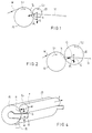
- Figures A and B are schematic illustrations of some problems of nip loads or linear loads known in prior art, the solution of these problems being an object of the present invention.
- Figure 1 is a schematic illustration of the reeling process at the initial stage of the reeling.
- Figure 2 is a schematic illustration of the reeling process at the final stage of the reeling.
- Figure 3 is a schematic illustration of an arrangement in accordance with the invention in view of providing a uniform linear load or nip pressure.
- Figure 4 is a schematic illustration of a further exemplifying embodiment of the invention.
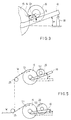
- Figure 5 is a schematic illustration of an embodiment of the arrangement in accordance with the invention which is suitable for use in continuous reeling.
- Figure 6 is a schematic illustration of a second embodiment of the arrangement in accordance with the invention which is suitable for use in continuous reeling.
- Figure 7 is a schematic illustration of an arrangement in accordance with the invention as fitted in connection with the process of exchange of reeling drum.
- the linear load between the reeling cylinder 15 and the reeling drum 20 is formed higher in the middle than at the edges.
- the linear load in the middle is denoted with the arrows Z.
- the higher linear load in the middle results from the effect of supporting of the reeling drum 20, which effect is denoted schematically with the arrows X.
- the web e.g. a paper web W
- the first roll i.e. the reeling cylinder 15
- the second roll i.e. the reeling drum 20
- both of which rolls 15,20 are revolving and form a nip N, into which nip the web W is passed and after which nip N the web W is reeled onto the second revolving roll, i.e. the reeling drum 20, which is supported by reeling rails 10.
- the reeling of the web W onto the reeling drum 20 against the reeling cylinder 15 is started at a point at which the component Gr of the force of gravity G of the earth directed at the centre point of the reeling cylinder 15 is suitable.
- the linear load effective in the nip N is uniform across the whole machine in the transverse direction and does not become excessively high at the middle.
- the sense of rotation of the reeling cylinder 15 is denoted with the reference S1, and the sense of rotation of the reeling drum 20 with the reference S2.
- the reeling drum 20 is supported by means of the reeling rails 10.
- the linear load in the transverse direction of the machine i.e. in the axial direction of the reeling drum or revolving roll 20
- the linear load is regulated by altering the position of the reeling drum 20 in relation to the reeling cylinder 15 so that the nip point N is changed and, at the same time, the magnitude of the force component Gr that produces the linear load is altered.
- the alteration of the force component Gr takes place most easily by adjusting the inclination of the reeling rails 10, i.e. the angle ⁇ .
- the own weight of the reeling drum 20 and the weight of the web reeled onto the drum produce the linear load or nip load at the point N.
- the angle ⁇ of inclination is, of course, made smaller to maintain a uniform linear load or nip load, preferably from about 20° to 1°.
- the angle ⁇ of inclination of the reeling rails 10 is adjusted by means of an actuator, e.g. a screw jack 30, a cylinder, or some other, corresponding member.
- an actuator e.g. a screw jack 30, a cylinder, or some other, corresponding member.
- a great number of well-known arrangements are suitable for members 30 of adjustment of the angle ⁇ of inclination.
- the reeling rails 10 are attached pivotally to the reeling cylinder 15, and the reeling rails 10 are preferably mounted to the centre point of the reeling cylinder 15.
- additional forces F are applied to the ends of the reeling drum 20 in a direction perpendicular to the axial direction of the roll by means of suitable members 35, e.g. means for supporting and shifting the reeling drum, in which case it is possible to control and to regulate the nip load or linear load in the transverse direction of the machine, i.e. in the axial direction of the reeling drum 20. If it is desirable to act upon the transverse profile of linear load by means of the above regulation operation and by the intermediate of the additional forces F while, at the same time, keeping the level of overall linear load unchanged, the angle ⁇ of inclination can be adjusted so that the effect of the additional forces F on the level of overall linear load is compensated for.
- the linear load or nip load in the transverse direction of the machine is regulated in the middle by changing the positions of the reeling cylinder 15 and the reeling drum 20 in relation to each other, e.g., by altering the angle ⁇ of inclination of the rails 10.
- the angle ⁇ of inclination is made larger, the linear load or nip load is increased in the middle, and when the angle ⁇ of inclination is made smaller, the linear load or nip load is reduced in the middle.
- the additional forces F By means of the additional forces F, the nip load or linear load is increased or reduced in the lateral areas.
- the overall linear load can be regulated in the desired way in the nip.
- the arrangement of the invention is suitable for use when the reeling is continuous.
- a construction is shown in which two systems of reeling cylinders 15 and rails 10 are employed.
- the web W guide rolls are denoted with the reference numeral 25.
- the angle ⁇ is made smaller. After the first jumbo roll 20 has become complete, the web W is passed to the other reeling system, which operates in a similar way.
- a second possibility is illustrated for a system in which two systems of reeling cylinders 15 and rails 10 are employed.
- the web W is passed over the guide rolls 25 onto the reeling cylinder 15, and from there further onto the reeling drum 20 supported on the rail 10. Upon completion of the reeling, the web W is guided to the other reeling system.
- the dashed lines indicate the positions of the rails 10 and the reeling drums 20 when the jumbo rolls are complete.
- the exchange of drum from the primary rails 10 onto the secondary rails 11 is carried out so that the exchange is carried out by means of the primary rails 10 while the full jumbo roll 20 revolves on the secondary rails 11.
- the full jumbo roll 21 is shifted to the braking position, whereupon the primary rails 10 can be shifted to a position optimal in view of the linear load.
- the shift onto the secondary rails 11 takes place by shifting the secondary rails 11 to the same angle ⁇ with the primary rolls 10, whereby the replacing reeling drum rolls over the joint, during and after which time the primary rails 10 and the secondary rails 11 move as synchronized while adjusting the linear load.
- the secondary rails 11 may also be fixed stationarily, in which case the regulation of the linear load takes place on said rails normally by means of reeling forks.
Landscapes
- Replacement Of Web Rolls (AREA)
- Winding Of Webs (AREA)
Applications Claiming Priority (2)
| Application Number | Priority Date | Filing Date | Title |
|---|---|---|---|
| FI905283A FI89701C (fi) | 1990-10-26 | 1990-10-26 | Rullainlaite ja menetelmä nippipaineen säätämiseksi rullainlaitteessa |
| FI905283 | 1990-10-26 |
Publications (2)
| Publication Number | Publication Date |
|---|---|
| EP0483093A1 EP0483093A1 (en) | 1992-04-29 |
| EP0483093B1 true EP0483093B1 (en) | 1996-01-03 |
Family
ID=8531315
Family Applications (1)
| Application Number | Title | Priority Date | Filing Date |
|---|---|---|---|
| EP19910850261 Expired - Lifetime EP0483093B1 (en) | 1990-10-26 | 1991-10-22 | Reel-up and method for regulation of the nip pressure in a reel-up |
Country Status (5)
| Country | Link |
|---|---|
| EP (1) | EP0483093B1 (fi) |
| JP (1) | JP2997353B2 (fi) |
| CA (1) | CA2054250C (fi) |
| DE (1) | DE69116086T2 (fi) |
| FI (1) | FI89701C (fi) |
Cited By (12)
| Publication number | Priority date | Publication date | Assignee | Title |
|---|---|---|---|---|
| US5370327A (en) * | 1993-05-06 | 1994-12-06 | Beloit Technologies, Inc. | Method and apparatus for reeling a wound web roll |
| US5544841A (en) * | 1994-08-18 | 1996-08-13 | Beloit Technologies, Inc. | Method and apparatus for reeling a traveling web into a wound web roll |
| US5553805A (en) * | 1993-11-26 | 1996-09-10 | R+E,Uml U+Ee Egg; Anton | Process and apparatus for winding sheet material |
| US5560566A (en) * | 1994-11-14 | 1996-10-01 | Beloit Technologies, Inc. | Winder with elevated spool support rail |
| US5664737A (en) * | 1995-10-10 | 1997-09-09 | Beloit Technologies, Inc. | Centerwind assist for a paper winder system |
| US5673870A (en) * | 1995-12-19 | 1997-10-07 | Beloit Technologies, Inc. | Method and apparatus for reeling a traveling paper web |
| US5845868A (en) * | 1997-07-03 | 1998-12-08 | Valmet-Karlstad Ab | Apparatus and method for winding paper |
| US5901918A (en) * | 1997-07-03 | 1999-05-11 | Valmet-Karlstad Ab | Apparatus and method for winding paper |
| WO2001042118A2 (en) * | 1999-12-09 | 2001-06-14 | Metso Paper, Inc. | Method in threading of a paper web |
| US6585186B1 (en) | 1998-05-27 | 2003-07-01 | Metso Paper, Inc. | Method in reeling of a paper or paperboard web and reel-up for a paper or paperboard web |
| US6629659B1 (en) | 1998-02-17 | 2003-10-07 | Metso Paper, Inc. | Method and apparatus for measuring web tension profile to control the reeling of a web |
| CN109761080A (zh) * | 2018-12-31 | 2019-05-17 | 天津市旭辉恒远塑料包装股份有限公司 | 防散压辊 |
Families Citing this family (4)
| Publication number | Priority date | Publication date | Assignee | Title |
|---|---|---|---|---|
| CA2150168C (en) * | 1995-05-25 | 2003-01-14 | Djuro Kremar | Center wind assist driving wheel mechanism |
| FI111927B (fi) * | 2000-03-07 | 2003-10-15 | Metso Paper Inc | Menetelmä ja laite paperirainan kiinnirullauksessa |
| CN114044392B (zh) * | 2021-11-23 | 2022-12-09 | 西安泰金工业电化学技术有限公司 | 一种生箔机自调节收卷压辊装置及调节方法 |
| CN114684648A (zh) * | 2022-03-22 | 2022-07-01 | 江西铜博科技有限公司 | 一种铜箔生产压辊装置 |
Family Cites Families (5)
| Publication number | Priority date | Publication date | Assignee | Title |
|---|---|---|---|---|
| US1950159A (en) * | 1931-04-06 | 1934-03-06 | Beloit Iron Works | Paper winder |
| US2176198A (en) * | 1938-01-24 | 1939-10-17 | Beloit Iron Works | Paper winder |
| US2528713A (en) * | 1946-01-31 | 1950-11-07 | Thomson William Robert | Paper reeling method and apparatus |
| FR1175214A (fr) * | 1957-05-16 | 1959-03-23 | Const Mecanique | Dispositif de rebobinage |
| FI71107C (fi) * | 1984-11-27 | 1986-11-24 | Valmet Oy | Foerfarande vid styrning av rullstolen av en pappersbana |
-
1990
- 1990-10-26 FI FI905283A patent/FI89701C/fi active IP Right Grant
-
1991
- 1991-10-22 DE DE1991616086 patent/DE69116086T2/de not_active Expired - Lifetime
- 1991-10-22 EP EP19910850261 patent/EP0483093B1/en not_active Expired - Lifetime
- 1991-10-25 CA CA 2054250 patent/CA2054250C/en not_active Expired - Fee Related
- 1991-10-28 JP JP3307124A patent/JP2997353B2/ja not_active Expired - Fee Related
Cited By (13)
| Publication number | Priority date | Publication date | Assignee | Title |
|---|---|---|---|---|
| US5370327A (en) * | 1993-05-06 | 1994-12-06 | Beloit Technologies, Inc. | Method and apparatus for reeling a wound web roll |
| US5553805A (en) * | 1993-11-26 | 1996-09-10 | R+E,Uml U+Ee Egg; Anton | Process and apparatus for winding sheet material |
| US5544841A (en) * | 1994-08-18 | 1996-08-13 | Beloit Technologies, Inc. | Method and apparatus for reeling a traveling web into a wound web roll |
| US5560566A (en) * | 1994-11-14 | 1996-10-01 | Beloit Technologies, Inc. | Winder with elevated spool support rail |
| US5664737A (en) * | 1995-10-10 | 1997-09-09 | Beloit Technologies, Inc. | Centerwind assist for a paper winder system |
| US5673870A (en) * | 1995-12-19 | 1997-10-07 | Beloit Technologies, Inc. | Method and apparatus for reeling a traveling paper web |
| US5845868A (en) * | 1997-07-03 | 1998-12-08 | Valmet-Karlstad Ab | Apparatus and method for winding paper |
| US5901918A (en) * | 1997-07-03 | 1999-05-11 | Valmet-Karlstad Ab | Apparatus and method for winding paper |
| US6629659B1 (en) | 1998-02-17 | 2003-10-07 | Metso Paper, Inc. | Method and apparatus for measuring web tension profile to control the reeling of a web |
| US6585186B1 (en) | 1998-05-27 | 2003-07-01 | Metso Paper, Inc. | Method in reeling of a paper or paperboard web and reel-up for a paper or paperboard web |
| WO2001042118A2 (en) * | 1999-12-09 | 2001-06-14 | Metso Paper, Inc. | Method in threading of a paper web |
| CN109761080A (zh) * | 2018-12-31 | 2019-05-17 | 天津市旭辉恒远塑料包装股份有限公司 | 防散压辊 |
| CN109761080B (zh) * | 2018-12-31 | 2024-04-19 | 天津市旭辉恒远塑料包装股份有限公司 | 防散压辊 |
Also Published As
| Publication number | Publication date |
|---|---|
| DE69116086D1 (de) | 1996-02-15 |
| FI89701C (fi) | 1999-01-19 |
| FI905283A0 (fi) | 1990-10-26 |
| JPH04266352A (ja) | 1992-09-22 |
| FI905283A (fi) | 1992-04-27 |
| JP2997353B2 (ja) | 2000-01-11 |
| FI89701B (fi) | 1993-07-30 |
| CA2054250C (en) | 2004-06-15 |
| EP0483093A1 (en) | 1992-04-29 |
| DE69116086T2 (de) | 1996-05-30 |
| CA2054250A1 (en) | 1992-04-27 |
Similar Documents
| Publication | Publication Date | Title |
|---|---|---|
| EP0483093B1 (en) | Reel-up and method for regulation of the nip pressure in a reel-up | |
| US4746076A (en) | Winder device | |
| CA2060468C (en) | Method and apparatus for winding a traveling web | |
| US4883233A (en) | Method for controlling the reeling of a web | |
| KR100309577B1 (ko) | 웨브의권취장치 | |
| US4921183A (en) | Method and device for the reeling of a web | |
| FI100099B (fi) | Menetelmä ja laite paperirainan rullauksessa | |
| US6089496A (en) | Web tension control system for a winding structure | |
| JP2002503610A (ja) | ウエブ巻き上げ方法及び装置 | |
| JPH0157014B2 (fi) | ||
| CA2306467C (en) | Paper web treatment control system based on energy supplied to a bearing | |
| US7011267B2 (en) | Method and device for winding a paper or board web | |
| CA2260508A1 (en) | Method for operating a calender roll system, and calender roll system | |
| US6164586A (en) | Support drum assembly with cross-shaft linkage for variable backlash control |
Legal Events
| Date | Code | Title | Description |
|---|---|---|---|
| PUAI | Public reference made under article 153(3) epc to a published international application that has entered the european phase |
Free format text: ORIGINAL CODE: 0009012 |
|
| AK | Designated contracting states |
Kind code of ref document: A1 Designated state(s): DE FR GB IT SE |
|
| 17P | Request for examination filed |
Effective date: 19921014 |
|
| 17Q | First examination report despatched |
Effective date: 19940203 |
|
| GRAA | (expected) grant |
Free format text: ORIGINAL CODE: 0009210 |
|
| AK | Designated contracting states |
Kind code of ref document: B1 Designated state(s): DE FR GB IT SE |
|
| REF | Corresponds to: |
Ref document number: 69116086 Country of ref document: DE Date of ref document: 19960215 |
|
| ITF | It: translation for a ep patent filed |
Owner name: STUDIO CONS. BREVETTUALE S.R.L. |
|
| ET | Fr: translation filed | ||
| PLBE | No opposition filed within time limit |
Free format text: ORIGINAL CODE: 0009261 |
|
| STAA | Information on the status of an ep patent application or granted ep patent |
Free format text: STATUS: NO OPPOSITION FILED WITHIN TIME LIMIT |
|
| 26N | No opposition filed | ||
| REG | Reference to a national code |
Ref country code: GB Ref legal event code: IF02 |
|
| PGFP | Annual fee paid to national office [announced via postgrant information from national office to epo] |
Ref country code: SE Payment date: 20081014 Year of fee payment: 18 |
|
| PGFP | Annual fee paid to national office [announced via postgrant information from national office to epo] |
Ref country code: FR Payment date: 20081014 Year of fee payment: 18 |
|
| PGFP | Annual fee paid to national office [announced via postgrant information from national office to epo] |
Ref country code: GB Payment date: 20081021 Year of fee payment: 18 |
|
| EUG | Se: european patent has lapsed | ||
| REG | Reference to a national code |
Ref country code: FR Ref legal event code: ST Effective date: 20100630 |
|
| PG25 | Lapsed in a contracting state [announced via postgrant information from national office to epo] |
Ref country code: FR Free format text: LAPSE BECAUSE OF NON-PAYMENT OF DUE FEES Effective date: 20091102 |
|
| PG25 | Lapsed in a contracting state [announced via postgrant information from national office to epo] |
Ref country code: GB Free format text: LAPSE BECAUSE OF NON-PAYMENT OF DUE FEES Effective date: 20091022 |
|
| PGFP | Annual fee paid to national office [announced via postgrant information from national office to epo] |
Ref country code: DE Payment date: 20101022 Year of fee payment: 20 |
|
| PGFP | Annual fee paid to national office [announced via postgrant information from national office to epo] |
Ref country code: IT Payment date: 20101026 Year of fee payment: 20 |
|
| PG25 | Lapsed in a contracting state [announced via postgrant information from national office to epo] |
Ref country code: SE Free format text: LAPSE BECAUSE OF NON-PAYMENT OF DUE FEES Effective date: 20091023 |
|
| REG | Reference to a national code |
Ref country code: DE Ref legal event code: R071 Ref document number: 69116086 Country of ref document: DE |
|
| REG | Reference to a national code |
Ref country code: DE Ref legal event code: R071 Ref document number: 69116086 Country of ref document: DE |
|
| PG25 | Lapsed in a contracting state [announced via postgrant information from national office to epo] |
Ref country code: DE Free format text: LAPSE BECAUSE OF EXPIRATION OF PROTECTION Effective date: 20111023 |