EP0482532A2 - Anordnung zur selektiven Kopplung mehrerer Module mit einem Prozessor - Google Patents
Anordnung zur selektiven Kopplung mehrerer Module mit einem Prozessor Download PDFInfo
- Publication number
- EP0482532A2 EP0482532A2 EP91117851A EP91117851A EP0482532A2 EP 0482532 A2 EP0482532 A2 EP 0482532A2 EP 91117851 A EP91117851 A EP 91117851A EP 91117851 A EP91117851 A EP 91117851A EP 0482532 A2 EP0482532 A2 EP 0482532A2
- Authority
- EP
- European Patent Office
- Prior art keywords
- module
- modules
- processor
- coupled
- bus
- Prior art date
- Legal status (The legal status is an assumption and is not a legal conclusion. Google has not performed a legal analysis and makes no representation as to the accuracy of the status listed.)
- Withdrawn
Links
Images

Classifications
-
- G—PHYSICS
- G06—COMPUTING OR CALCULATING; COUNTING
- G06F—ELECTRIC DIGITAL DATA PROCESSING
- G06F3/00—Input arrangements for transferring data to be processed into a form capable of being handled by the computer; Output arrangements for transferring data from processing unit to output unit, e.g. interface arrangements
- G06F3/06—Digital input from, or digital output to, record carriers, e.g. RAID, emulated record carriers or networked record carriers
- G06F3/0601—Interfaces specially adapted for storage systems
-
- G—PHYSICS
- G06—COMPUTING OR CALCULATING; COUNTING
- G06F—ELECTRIC DIGITAL DATA PROCESSING
- G06F13/00—Interconnection of, or transfer of information or other signals between, memories, input/output devices or central processing units
- G06F13/38—Information transfer, e.g. on bus
- G06F13/42—Bus transfer protocol, e.g. handshake; Synchronisation
- G06F13/4204—Bus transfer protocol, e.g. handshake; Synchronisation on a parallel bus
- G06F13/4221—Bus transfer protocol, e.g. handshake; Synchronisation on a parallel bus being an input/output bus, e.g. ISA bus, EISA bus, PCI bus, SCSI bus
- G06F13/4226—Bus transfer protocol, e.g. handshake; Synchronisation on a parallel bus being an input/output bus, e.g. ISA bus, EISA bus, PCI bus, SCSI bus with asynchronous protocol
-
- G—PHYSICS
- G06—COMPUTING OR CALCULATING; COUNTING
- G06F—ELECTRIC DIGITAL DATA PROCESSING
- G06F3/00—Input arrangements for transferring data to be processed into a form capable of being handled by the computer; Output arrangements for transferring data from processing unit to output unit, e.g. interface arrangements
- G06F3/06—Digital input from, or digital output to, record carriers, e.g. RAID, emulated record carriers or networked record carriers
- G06F3/0601—Interfaces specially adapted for storage systems
- G06F3/0668—Interfaces specially adapted for storage systems adopting a particular infrastructure
- G06F3/0671—In-line storage system
- G06F3/0673—Single storage device
Definitions
- the invention relates to an arrangement and a method for the selective coupling of several modules, in particular disk drives and memory modules with a processor.
- processor is understood to mean any device for data processing, for example a microprocessor, a computer or a mainframe.
- the invention has for its object to reduce the installation effort if any active and passive data processing modules, for example disk drives, other memories and / or peripheral devices are combined with one another and with at least one processor to form a function or assembly or their configuration is changed or expanded.
- any active and passive data processing modules for example disk drives, other memories and / or peripheral devices are combined with one another and with at least one processor to form a function or assembly or their configuration is changed or expanded.
- the user should be able to reconfigure and reconfigure any number of devices and modules.
- each of the modules to be coupled to the processor has a microcontroller for the internal control of the power supply and the maneuvering paths (jumpers) and for the exchange of status and information with the coupled modules and the processor and an operator control coupled with the microcontroller.
- each module can be selectively connected in series via their inputs and outputs and can be coupled to the processor via a common bus; that each microprocessor is assigned means for forming a bus terminating resistor, which are effective when the associated module is the last module in the row; and that each module has an identifier managed by the microcontroller to distinguish the modules of the assembly, to communicate the modules with one another and with the processor and is assigned to request access to the module.
- the invention makes it possible to provide an existing data processing system externally with any module, for example a hard disk module or other mass storage device or peripheral devices, but also with a further computer system and to link it functionally.
- This link to the processor can easily be configured by the user and changed as required.
- the microcontroller assigned to each individual module generally takes over the complex maneuvering functions previously required for system changes or expansions.
- the microcontroller of the last module in the row ensures that the bus terminating resistor is always required.
- the special function of the mass storage device or peripheral device of the module is irrelevant for the integration into the function or assembly provided according to the invention. The user is therefore able to expand the existing system with one or more hard disks, from which, if necessary, different operating systems for the processor can be loaded by cold or warm start.
- the various mass storage devices can also be removed from the assembly when not in use and can be stored elsewhere, protected from access by unauthorized users. Later, they can be integrated back into the system without any problems, regardless of the physical installation sequence.
- Another advantage of the invention is that in the event of a processor defect, one or more modules can be removed from the system and used in conjunction with another computer without complicated adaptation to the new system environment.
- a preferably electrically programmable program memory and a direct access memory are assigned to each microcontroller.
- Appropriate programming of the program memory means that the measures required when installing a module in an existing assembly are limited to the purely electrical connections and a few integration commands that can be called up at the push of a button.
- a universal system expansion is particularly favored by the fact that a power supply module is provided for the power supply of the modules interconnected to form a structural or functional group.
- one of the modules connected to an assembly is designed and suitable as a master to assign identifiers to the other module modules organized as slave modules and to configure all module modules.
- the method for the selective coupling of several modules with one processor is characterized according to the invention in that an input of a first module is connected to the processor via a data bus; several further modules are connected in series to the output of the first module, the connection from module to module being established in each case via a data cable and the data bus of the last module connected in the series being terminated with a terminating resistor; and the coupled modules are configured in that: at least one of the further modules is selected by simultaneously pressing a selection button on the at least one further module and a configuration button on the first module and is coupled to the first module to form a first logical configuration group and the selective coupling is confirmed in the configuration group by pressing an Enter key on the first module.
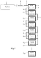
- a series of modules 3, 41 ... 4 x are assigned to a computer 1.
- the modules 3, 41 ... 4 x are connected to each other and to the computer via a bus 51, 52, which is controlled by the computer 1 via a bus controller 2.
- the data bus 51 connects the bus controller 2 and the first module 3 and is used for exchanging information and data of the modules 3, 41 ... 4 x with the computer 1. All combined to form an assembly modules 3 and 4 41 ... x are connected via data cables 52, one data cable connecting two modules in such a way that the modules form the chain shown in FIG. 1.
- a data bus arrangement is provided in each data cable.
- Each module has a functional unit, for example a hard disk unit, a floppy disk drive or another peripheral device, and has a microcontroller, via which the individual modules can exchange information and status signals with one another.
- the first module 3 contains, as a special functional unit, a power supply unit for supplying power to all downstream modules, ie modules belonging to the same module. This relieves the power supply of the computer 1 and ensures a reliable and independent power supply for a limited number of modules. The power supply to the remaining modules is provided by additional lines included in the 52 data cable.
- the data and information lines of the bus 5 1 are also continued in the data cables 5 2.
- the data cable 52 contain additional control lines for exchanging information and control commands between the microcontrollers 7 of the modules 3, 41 ... 4 x .
- the functional units (eg hard drives - Fig. 1) of the modules 41 ... 4 x can access the data bus of the data cable 52 in a known manner via their interfaces.
- the microcontrollers 7 of the modules 3, 4 1 ... 4 x can exchange data serially with one another via selected lines of the data bus if there is no data exchange of the functional units via these lines of the data bus at this time.
- module 3 is designed as a master module. In addition to the power supply unit, it has control devices for configuring the assembly. As will be explained further below, a special control and display panel is provided for this purpose.
- the other modules 41 ... 4 x are designed as slave modules and assigned to the master module.
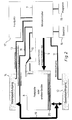
- the structure of the individual modules belonging to the system according to FIG. 1 is shown as an example in FIG. 2.
- the module has a functional unit 8 (for example a hard disk), a microcontroller 7 with an associated ROM 15 for storing programs and an associated information memory 16 (for example an EEPROM) and a front panel 17 with an operating and display panel.
- the module has two interfaces, a data cable input 12 and a data cable output 14, via which it can be connected to other modules using the data cable 5.
- the data bus connected via a data cable 52 to the data cable input 12 is internal via the Data bus 19 to the data cable output 14 and then optionally via a further data cable 52 to the next module.
- the interface 20 of the functional unit 8, for example the hard disk, is coupled to this data bus 19 via a coupling 21.
- a connection port 22 of the microcontroller 7 is connected to the data cable input 12 via status lines 11.
- An output connection port 23 of the microcontroller 7 is connected to the data cable output 14 via status lines 13.
- the microcontroller 7 sets options of the functional unit 8 via lines 9. Such options relate either to the functioning of the functional unit itself (eg write protection, parity) or to the coupling of the functional unit 8 to the data bus 19 (connection of a bus terminating resistor).
- the microcontroller 7 controls the power supply of the functional unit 8 via the line 10.
- the microcontroller 7 can exchange data and control information with the other modules via the status lines 11 and 13 and additionally via the serial data line 18 coupled to the data bus 19. By coupling to the control and display panel 17, the microcontroller 7 can receive signals triggered by operator actions and output signals via the displays.
- Fig. 3 shows the front panels 17 M , 17 S2 , 17 S1 of the modules of an assembly consisting of a master module and two attached slave modules.
- the interconnection and configuration of the modules will be explained on the basis of this exemplary embodiment.
- an input of the master module 3 is connected to the processor 1 via a data bus 5 1.
- slave modules 41 ... 4 x fitted like a tower and data cable inputs 12 and data cable outlets 14 connected in pairs.
- the uppermost slave module 4 x of the tower thus has a free data cable output 14.
- a module is configured in the following way: First, a system group is created on the master module (17 M ) selected by pressing a system key 24. First of all, assume that all modules of an assembly are assigned to the same system group (System 1). After pressing the system key 24, the configuration key 29 (Config) is pressed on the master module (17 M ) and at the same time the selection key 28 (Select) is pressed on the selected slave module (e.g. 17 S1 ). If the selected module (17 S1 ) is not configured, this configuration request is accepted. This is indicated by the key LEDs of the three keys 24a, 28a, 29a (Config 29 and System-1 24 on the master module and Select 28 on the slave module) lighting up. Then the enter key 30 on the master module can be pressed to confirm the assignment. The configuration is confirmed and saved, and the LEDs 28a, 29a, 30a go out.
- the first logical configuration group produced by this method can, for example, form a first logical drive (eg drive C) of the processor 1. This procedure can then be repeated on a second slave module (17 S2 ). A second logical configuration group is formed from the second slave module (17 S2 ) and the master module (17 M ). The next free (second) logical module name (eg drive D) of the first system group is assigned to the second slave module.
- a first logical drive eg drive C
- This procedure can then be repeated on a second slave module (17 S2 ).
- a second logical configuration group is formed from the second slave module (17 S2 ) and the master module (17 M ).
- the next free (second) logical module name (eg drive D) of the first system group is assigned to the second slave module.
- a non-erasable memory of the master module 3 stores a serial number (identification code or identifier) which has already been assigned in the manufacturing process and which uniquely identifies the master module.
- the slave modules (automatically) adopt the identifier of the master module. All modules (master and slave modules) of a newly configured module therefore have a common identifier. In normal use, they keep this identifier for the entire remaining period of use.
- the assignment of the slave modules to one of the system groups is indicated by the LED 25 on the associated one Slave module displayed.
- the number assigned to the logical configuration group is indicated by the LEDs 26.
- the assignment of the slave modules and the master module to the configuration groups is stored in the information memories 16 (FIG. 2).
- the configuration once saved is retained even if the module is dismantled and then reassembled in a different physical sequence.
- both slave modules (17 S1 and 17 S2 ) can be assigned to the first configuration group together with the master module (17 M ). If the module is dismantled in this case and only one of the two slave modules (17 S2 ) is later replaced, the incompleteness of the configuration group is shown by the flashing of the assigned LED 26. Slave modules of an incomplete configuration group cannot be activated.
- the configuration groups of an assembly can be selectively assigned to different system groups (System 1, System 2, ). This is done by selecting the corresponding system buttons 24 on the master module (17 M ) before configuring.
- each of the four system groups can have up to six configuration groups (ie, for example, six logical drives: C, D, E, F, G, H).
- one system group can be activated by pressing the corresponding system key 24.
- the active system group is indicated by LEDs 31 on the master module (17 M ).
- the system groups enable simple loading of different operating systems (eg DOS, UNIX, OS / 2) when resetting or warm up the computer 1.
- the first configuration group of a system group is designed as a drive unit with the files necessary for booting the operating system.
- Modules can be coupled with any other master modules. If a slave module configured on a first master module (with a first identifier) is placed elsewhere on another master module (with a different identifier), the module recognizes the slave module as a guest module. This is indicated by the lighting of the guest LED of the LED display 25 of the slave module.
Landscapes
- Engineering & Computer Science (AREA)
- Theoretical Computer Science (AREA)
- Physics & Mathematics (AREA)
- General Engineering & Computer Science (AREA)
- General Physics & Mathematics (AREA)
- Human Computer Interaction (AREA)
- Control By Computers (AREA)
- Programmable Controllers (AREA)
Applications Claiming Priority (2)
| Application Number | Priority Date | Filing Date | Title |
|---|---|---|---|
| DE4033464 | 1990-10-20 | ||
| DE4033464A DE4033464A1 (de) | 1990-10-20 | 1990-10-20 | Anordnung zur selektiven kopplung mehrerer module mit einem prozessor |
Publications (2)
| Publication Number | Publication Date |
|---|---|
| EP0482532A2 true EP0482532A2 (de) | 1992-04-29 |
| EP0482532A3 EP0482532A3 (enExample) | 1994-08-03 |
Family
ID=6416754
Family Applications (1)
| Application Number | Title | Priority Date | Filing Date |
|---|---|---|---|
| EP91117851A Withdrawn EP0482532A2 (de) | 1990-10-20 | 1991-10-18 | Anordnung zur selektiven Kopplung mehrerer Module mit einem Prozessor |
Country Status (2)
| Country | Link |
|---|---|
| EP (1) | EP0482532A2 (enExample) |
| DE (1) | DE4033464A1 (enExample) |
Cited By (3)
| Publication number | Priority date | Publication date | Assignee | Title |
|---|---|---|---|---|
| US6021465A (en) * | 1995-08-11 | 2000-02-01 | Siemens Nixdorf Informationssysteme Aktiengesellschaft | Arrangement for the connecting peripheral storage devices |
| EP0723223A3 (en) * | 1995-01-18 | 2005-09-21 | Hewlett-Packard Company, A Delaware Corporation | Identifying controller pairs in a dual controller disk array |
| CN112467872A (zh) * | 2020-10-21 | 2021-03-09 | 威海锐恩电子股份有限公司 | 一种基于分布式采集架构的电力能源终端设备 |
Family Cites Families (8)
| Publication number | Priority date | Publication date | Assignee | Title |
|---|---|---|---|---|
| US4183084A (en) * | 1977-06-06 | 1980-01-08 | Digital Equipment Corporation | Secondary storage facility with serial transfer of control messages |
| US4360870A (en) * | 1980-07-30 | 1982-11-23 | International Business Machines Corporation | Programmable I/O device identification |
| FR2561428B1 (fr) * | 1984-03-16 | 1986-09-12 | Bull Sa | Procede d'enregistrement dans une memoire a disques et systeme de memoire a disques |
| JPS6278623A (ja) * | 1985-10-02 | 1987-04-10 | Toshiba Corp | 磁気デイスク装置 |
| JPH0821153B2 (ja) * | 1987-10-12 | 1996-03-04 | オリンパス光学工業株式会社 | 形状寸法測定装置におけるデータ転送システム |
| DE3736081A1 (de) * | 1987-10-24 | 1989-05-03 | Licentia Gmbh | Verfahren und vorrichtung zur adresseneinstellung von an einen bus angeschlossenen teilnehmern |
| US4870643A (en) * | 1987-11-06 | 1989-09-26 | Micropolis Corporation | Parallel drive array storage system |
| AU630635B2 (en) * | 1988-11-14 | 1992-11-05 | Emc Corporation | Arrayed disk drive system and method |
-
1990
- 1990-10-20 DE DE4033464A patent/DE4033464A1/de not_active Withdrawn
-
1991
- 1991-10-18 EP EP91117851A patent/EP0482532A2/de not_active Withdrawn
Cited By (3)
| Publication number | Priority date | Publication date | Assignee | Title |
|---|---|---|---|---|
| EP0723223A3 (en) * | 1995-01-18 | 2005-09-21 | Hewlett-Packard Company, A Delaware Corporation | Identifying controller pairs in a dual controller disk array |
| US6021465A (en) * | 1995-08-11 | 2000-02-01 | Siemens Nixdorf Informationssysteme Aktiengesellschaft | Arrangement for the connecting peripheral storage devices |
| CN112467872A (zh) * | 2020-10-21 | 2021-03-09 | 威海锐恩电子股份有限公司 | 一种基于分布式采集架构的电力能源终端设备 |
Also Published As
| Publication number | Publication date |
|---|---|
| EP0482532A3 (enExample) | 1994-08-03 |
| DE4033464A1 (de) | 1992-04-23 |
Similar Documents
| Publication | Publication Date | Title |
|---|---|---|
| DE69128521T2 (de) | Nichtflüchtige seriell programmierbare Anordnungen | |
| EP0624832B1 (de) | Elektronische Steuereinrichtung für eine modulartig aufgebaute Ventilstation | |
| DE2321260C2 (de) | Multiprozessor-Datenverarbeitungsanlage mit mehreren rekonfigurierbaren Datenverarbeitungsgruppen | |
| DE69834401T2 (de) | Businterfacesystem und verfahren | |
| DE3751853T2 (de) | Vorrichtung für ein fehlertolerantes Rechnersystem mit erweiterungsfähigem Prozessorabschnitt | |
| DE69818089T2 (de) | Intelligentes kraftfahrzeugstromverteilungssystem und sein herstellungsverfahren | |
| DE60014938T2 (de) | Skalierbares datenerfassungs-/ und rechengerät | |
| EP3961317B1 (de) | Verfahren zur konfiguration einer modularen sicherheitsschaltvorrichtung | |
| DE69523223T2 (de) | Steuergerät | |
| DE19756564A1 (de) | Nachrichtennetz mit automatischer Knotenkonfiguration bei identischen Knoten | |
| EP0434986A2 (de) | Verfahren zur Inbetriebnahme einer an ein elektronisches Steuerungssystem angeschlossenen Baugruppe | |
| DE69428538T2 (de) | Verfahren zum konfigurieren von mehreren adapterkarten auf einem bus | |
| DE2404146A1 (de) | Digitales, hierarchisch in wenigstens drei hierarchie-stufen aufgebautes speichersystem | |
| DE3013070C2 (de) | Schaltungsanordnung zur Bearbeitung von aus mehreren peripheren Geräten herangeführten Anforderungssignalen innerhalb einer datenverarbeitenden Einrichtung | |
| EP2214068A1 (de) | Automatisierungssystem mit einem programmierbaren Matrixmodul | |
| EP1622039B1 (de) | Verfahren und Vorrichtung zur Adressvergabe an Teilnehmer eines Bussystems | |
| EP0482532A2 (de) | Anordnung zur selektiven Kopplung mehrerer Module mit einem Prozessor | |
| DE69602527T2 (de) | Anzeigevorrichtung für programmierbaren automaten | |
| DE112021006390T5 (de) | Netzwerksystem, kommunikationsverfahren und kommunikationsprogramm | |
| WO2004036324A1 (de) | Verfahren und vorrichtung zur prozessautomatisierung mit redundanten steuergeräten zur ansteuerung von peripheriegeräten über ein bussystem | |
| DE3534465A1 (de) | Verbundsystem speicherprogrammierbarer steuerungen | |
| EP1099991B1 (de) | Verfahren zur Konfiguration von Aufzugssteuerungen | |
| EP0645034A1 (de) | Rechnersystem. | |
| EP1386200A2 (de) | Verfahren und system zur lückenlosen belegung von ein- und ausgabeadressen eines modularen steuersystems | |
| DE3942690C2 (de) | Anschlußstecker |
Legal Events
| Date | Code | Title | Description |
|---|---|---|---|
| PUAI | Public reference made under article 153(3) epc to a published international application that has entered the european phase |
Free format text: ORIGINAL CODE: 0009012 |
|
| AK | Designated contracting states |
Kind code of ref document: A2 Designated state(s): AT BE CH DE ES FR GB IT LI NL SE |
|
| PUAL | Search report despatched |
Free format text: ORIGINAL CODE: 0009013 |
|
| AK | Designated contracting states |
Kind code of ref document: A3 Designated state(s): AT BE CH DE ES FR GB IT LI NL SE |
|
| STAA | Information on the status of an ep patent application or granted ep patent |
Free format text: STATUS: THE APPLICATION IS DEEMED TO BE WITHDRAWN |
|
| 18D | Application deemed to be withdrawn |
Effective date: 19950204 |