EP0482401B1 - Verfahren zur Ultraschallüberwachung von Räumen, insbesondere bei Fahrzeugen - Google Patents
Verfahren zur Ultraschallüberwachung von Räumen, insbesondere bei Fahrzeugen Download PDFInfo
- Publication number
- EP0482401B1 EP0482401B1 EP91116937A EP91116937A EP0482401B1 EP 0482401 B1 EP0482401 B1 EP 0482401B1 EP 91116937 A EP91116937 A EP 91116937A EP 91116937 A EP91116937 A EP 91116937A EP 0482401 B1 EP0482401 B1 EP 0482401B1
- Authority
- EP
- European Patent Office
- Prior art keywords
- measurement
- process according
- alarm
- profiles
- pulse
- Prior art date
- Legal status (The legal status is an assumption and is not a legal conclusion. Google has not performed a legal analysis and makes no representation as to the accuracy of the status listed.)
- Expired - Lifetime
Links
- 238000000034 method Methods 0.000 title claims abstract description 43
- 238000002604 ultrasonography Methods 0.000 title claims description 16
- 238000005259 measurement Methods 0.000 claims abstract description 117
- 230000008569 process Effects 0.000 claims abstract description 21
- 238000011156 evaluation Methods 0.000 claims abstract description 12
- 230000001960 triggered effect Effects 0.000 claims abstract description 5
- 238000012544 monitoring process Methods 0.000 claims description 42
- 230000005540 biological transmission Effects 0.000 claims description 26
- 230000035945 sensitivity Effects 0.000 claims description 4
- 230000001419 dependent effect Effects 0.000 claims description 3
- 230000036962 time dependent Effects 0.000 claims description 2
- 230000001052 transient effect Effects 0.000 claims description 2
- 230000000694 effects Effects 0.000 abstract description 6
- 238000006073 displacement reaction Methods 0.000 description 9
- 230000008859 change Effects 0.000 description 6
- 230000007613 environmental effect Effects 0.000 description 4
- 230000008901 benefit Effects 0.000 description 3
- 230000002349 favourable effect Effects 0.000 description 3
- 230000002123 temporal effect Effects 0.000 description 3
- 230000005855 radiation Effects 0.000 description 2
- 101100322245 Caenorhabditis elegans des-2 gene Proteins 0.000 description 1
- 230000006399 behavior Effects 0.000 description 1
- 230000002146 bilateral effect Effects 0.000 description 1
- 239000002775 capsule Substances 0.000 description 1
- 238000005314 correlation function Methods 0.000 description 1
- 238000010586 diagram Methods 0.000 description 1
- 238000005265 energy consumption Methods 0.000 description 1
- 238000012854 evaluation process Methods 0.000 description 1
- 238000012806 monitoring device Methods 0.000 description 1
- 230000000704 physical effect Effects 0.000 description 1
- 230000000750 progressive effect Effects 0.000 description 1
- 230000009467 reduction Effects 0.000 description 1
- 230000007704 transition Effects 0.000 description 1
Images
Classifications
-
- G—PHYSICS
- G01—MEASURING; TESTING
- G01S—RADIO DIRECTION-FINDING; RADIO NAVIGATION; DETERMINING DISTANCE OR VELOCITY BY USE OF RADIO WAVES; LOCATING OR PRESENCE-DETECTING BY USE OF THE REFLECTION OR RERADIATION OF RADIO WAVES; ANALOGOUS ARRANGEMENTS USING OTHER WAVES
- G01S15/00—Systems using the reflection or reradiation of acoustic waves, e.g. sonar systems
- G01S15/02—Systems using the reflection or reradiation of acoustic waves, e.g. sonar systems using reflection of acoustic waves
- G01S15/04—Systems determining presence of a target
-
- B—PERFORMING OPERATIONS; TRANSPORTING
- B60—VEHICLES IN GENERAL
- B60R—VEHICLES, VEHICLE FITTINGS, OR VEHICLE PARTS, NOT OTHERWISE PROVIDED FOR
- B60R25/00—Fittings or systems for preventing or indicating unauthorised use or theft of vehicles
- B60R25/10—Fittings or systems for preventing or indicating unauthorised use or theft of vehicles actuating a signalling device
- B60R25/1004—Alarm systems characterised by the type of sensor, e.g. current sensing means
- B60R25/1009—Sonic sensors; Signal treatment therefor
-
- G—PHYSICS
- G08—SIGNALLING
- G08B—SIGNALLING OR CALLING SYSTEMS; ORDER TELEGRAPHS; ALARM SYSTEMS
- G08B13/00—Burglar, theft or intruder alarms
- G08B13/16—Actuation by interference with mechanical vibrations in air or other fluid
- G08B13/1609—Actuation by interference with mechanical vibrations in air or other fluid using active vibration detection systems
- G08B13/1618—Actuation by interference with mechanical vibrations in air or other fluid using active vibration detection systems using ultrasonic detection means
Definitions
- the invention relates to a monitoring method of the type specified in the preamble of claim 1. There are in principle two different monitoring methods.
- the first method works according to the echo principle, which is based on the Doppler effect.
- an impulse is sent and the echo received.
- the echo results in a different frequency.
- the frequency shift is used to trigger an alarm.
- the Doppler effect one can also evaluate the echo image, which also changes when there are changes in the monitoring room. This measuring method is relatively complex and unreliable.
- monitoring based on the evaluation of an interference field is more favorable (DE-OS 38 38 150).
- the transmitter of ultrasonic pulses on the one hand and the receiver of reflected signals on the walls and objects in the monitoring room on the other hand are active at the same time.
- An interference field, which is evaluated, arises from the superimposition of the transmission pulses and reflection signals in the monitoring room.
- an evaluator connected to the receiver is used, which always detects the measurement level of the received signal at defined points in time of a measurement period that is coordinated with the transmission duration, stores it as a time-dependent measurement profile and compares it point by point with the measurement profile obtained during a previous transmission pulse. According to the comparison result, one connected to the evaluator Alarms set or left ineffective.
- the invention is also based on this monitoring method.
- the invention is therefore based on the object of developing a reliable, simple method for ultrasound monitoring of the type mentioned in the preamble of claim 1, which is very sensitive but avoids false alarms. This is achieved according to the invention by the measures specified in the characterizing part of claim 1, which have the following special meaning.
- the starting point is to use the temporal structure of the interference field during two measuring periods to be compared with one another, but the measurement is based on the final state after the interference field has settled. It has been shown that this area, despite its change due to environmental influences, enables a surprisingly reliable evaluation. If thermals are effective in the monitoring room, different levels of measurement result in successive measuring steps, but the invention has recognized that as long as the spatial conditions in the monitoring room remain unchanged, the two measuring profiles to be compared with one another are at least partially similar to one another. The invention therefore proposes to overlay the measurement profiles to be compared with one another with their respective measurement times in accordance with the abscissa. Already then some sections of the two measurement profiles essentially coincide with each other within a predetermined level tolerance.
- the second measurement profile can have several divergence sections compared to the first. These are then gradually shifted in parallel in the ordinate direction with the aim of eliminating the deviations of the two measurement profiles in this divergence section as far as possible.
- the parallel displacement of the divergence sections follows in the same direction and preferably in the same step lengths, but in an individual number of steps that is less than or equal to a predetermined maximum number of steps.
- This maximum number of steps is expediently derived from the two measurement profiles to be compared with one another. For this purpose, one starts from a level difference at a defined point in time of the two measurement profiles, which is preferably, according to claim 2, the end time of the two measurement periods.
- the latter is particularly favorable because, at the end of the measuring times, the influences of the transient processes are certainly eliminated and a statement about the existing spatial conditions in the monitoring room is possible.
- This level difference first determines the direction in which the parallel shift takes place, that is to say whether the measuring profile to be shifted lies above or below the other measuring profile serving as a comparison.
- the stride lengths are determined by the sensitivity of the evaluator and are usually specified as a fixed value. This results in the maximum number of steps taking into account the level difference determined. In some divergence sections, the level difference is already fallen below before the maximum number of steps is reached. These sections of the measurement profile are no longer moved. The remaining sections of the measurement profile, which then still appear as divergence sections, are gradually increased up to the predetermined maximum number of steps moved further. The remaining cover deviations are a clear criterion for the presence of an alarm.
- a reliable and simple mode of operation is obtained if the transmit pulses are constructed in the form of pulse packets from a family of individual pulses. Depending on the thermals resulting in the monitoring room, the pause length between the pulse packets is changed and / or the number of individual pulses in the pulse packet is corrected according to claim 8. For a simpler comparison, the time intervals between the pulse packets will be kept as constant as possible despite all changes.
- the computing time for determining the measurement results can also be used as a measure of the thermals.
- the various sizes mentioned above are automatically changed in the evaluation process. This saves additional sensors, such as thermocouples or the like.
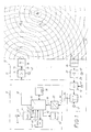
- FIG. 1 A device used to carry out the method according to the invention is shown in FIG. 1.
- the components shown in Fig. 1 are advantageously summarized in two housings 11, 11 ', which are illustrated there by chain lines.
- a processor 12 microwave-computer in the housing 11 'generates an electrical control signal 15 via an electrical line and an amplifier 14, which will hereinafter be referred to as "transmit pulse" 15.
- This acts on an ultrasound transmitter 18 connected to the output 17 of the amplifier 14, which generates an ultrasound pulse 19 illustrated by circles in FIG. 1.
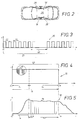
- the time course of the transmission pulse 15 can be seen in more detail in FIGS. 3, 4 and 6.
- the transmission pulse 15 has a start to determined by the processor 12, as is also the end of the pulse tn shown in FIG. 4, which is precisely defined for each measurement cycle. According to the ordinate of FIGS. 4 and 6, a constant transmission level S is maintained. The transmission pulse 15 is thus always reproducible.
- the device 10 automatically controls all parameters such as transmission amplitude, transmission time, sensitivity and the like by software. Adjustment is not necessary.
- the number of individual pulses can e.g. B. lie between one and fifteen individual pulses 22 and is controlled by the software.
- the transmission level is set optimally, which is important because the transmission and reception behavior of the ultrasound capsules serving as transmitter 18 and receiver 28 is strongly temperature-dependent.
- the duration of a single pulse 22, which is labeled To in FIG. 3, is z. B. 25 ⁇ s.
- the duration 21 of a pulse packet 21 is z. B. 0.8 ms. This results in a beat of approximately 1.3 kHz on the received signal, which is, however, irrelevant to the mode of operation of this monitoring device.
- the monitoring room 20 and the objects 23 located there are irradiated with the ultrasound pulse 19.
- the transmission pulse 19 is now reflected on the walls of the monitoring room, on the one hand, and the objects 23, on the other hand, which is also illustrated in FIG. 1, starting from the object 23 assumed as a point, by circular lines.
- These reflected signals 24 will hereinafter be referred to as "reflection signals” for short.
- the ultrasound pulses 19 and reflection signals 24 generate an interference field 25 in the monitoring space 20, which is illustrated in FIG. 1 by the intersection points of the circles.
- the interference field 25 is monitored by a receiver 28 at a defined location, which is referred to below as the “measurement location 26”.
- the receiver 28 sends the measurement signal to a receiving amplifier 27, at whose output 29 an AC voltage signal is then produced.
- the AC voltage signals are integrated via a full-wave rectifier 32 and a low-pass filter 33 and result in an electrical reception signal 30, the appearance of which can be seen in FIG. 5.
- the interference field has only built up in the monitoring space 20 after a defined settling time Ta. In the aforementioned embodiment, this takes approximately 16 ms, which corresponds to approximately twenty pulse packets. Only then, namely after this settling time Ta has elapsed from the start to of the transmission pulse 19, does the actual measuring period Tm begin.
- the horizontal time axis t of FIG. 5 is divided into times t1, t2 ... to tn, which will be referred to as "measurement times" in the following and always in a defined position at the start of the transmission pulse.
- the vertical axis of FIG. 5 shows the measurement level J.
- the measurement profile A0 is obtained as an electrical received signal.
- the measurement period Tm also begins with the measurement profile B0 in the same time coordination with the associated transmit pulse start to as with the measurement profile A0. If the spatial position of the objects 23 and the physical properties in the monitoring room 20 have not changed, the interference field 25 will be the same and therefore the measurement profile B0 will be the same as the previously excluded measurement profile A0. In practice, however, it was found that environmental influences, e.g. B. a thermal effect caused by solar radiation in the monitoring room 20, a change in the measurement profile B occurs.
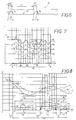
- FIG. 8 the situation is based on a complicated alarm case clarifies.
- the first measurement profile A0 is drawn in Fig. 8 as a solid line. Moving an object 23 in the monitoring room 20 then results in changes which are further falsified by thermals in the monitoring room 20.
- the second transmission pulse 15 should result in the second measurement profile B0, which is illustrated by the broken line in FIG. 8.
- Both measuring profiles A0, B0 are related by the processor 12 to corresponding measuring times t1 to tn, which is shown in FIG. 8 by superimposing the two curves. Values A0 (n) and B0 (n) which are dependent on the individual times are obtained and can now be compared with one another at times. This is done in the processor 12 arithmetically with the aid of a correlation C, which in the present case is determined as a quadratic deviation according to the formula
- the correlation C0 is a measure of the above-mentioned coverage deviation of the two measurement profiles A0, B0.
- the tolerable level difference identified by K in FIG. 8 should be present.
- the two measurement profiles should then be congruent if their measurement level J falls below this level tolerance K.
- the correlation C0 (n) is calculated for these three divergence areas. In the abscissa areas s0 ′ to s bis ′′′ three correlation curves C0 ′ to C0 ′′′ are obtained which are not equal to zero.
- the level difference D of the two measuring profiles A0, B0 is now determined, from which both the direction and the number of steps result, with which those located in the abscissa areas s0 'to s0 ′′′
- Divergence sections B0 ′, B0 ⁇ and B0 ′′′ step by step by a predetermined step length d must be shifted parallel to their original value. This is illustrated in Fig. 8 in the region of the divergence section B0 'by the parallel shifted curve B1 shown there. The same thing happens with the other two divergence sections B0 ⁇ and B0 ′′′, which merge into B1 ⁇ and B1 ′′′.
- the cover deviations C1 ' now extend over a smaller abscissa area s1' if you compare them with the previous cover deviations C0 ', which went over the larger abscissa area s0'.
- the existing convergence sections 11, 12 and 13 have thus become larger at the expense of the new divergence sections.
- the second measurement profile B0 ⁇ has smaller level values than the former A0, which is why the cover deviations increase with each shift, which can already be seen when the transition from C0 ⁇ to C1 ⁇ is shown. These deviations are thus increased in the course of the progressive stepwise parallel shift of this divergence section and can therefore be determined particularly clearly.
- the parallel shift is carried out up to the above-mentioned maximum number of steps M, which is realized in FIG. 8 by the two last calculated correlations C M-1 ⁇ and C M ⁇ . Only then is the parallel displacement process completed. Except for the abscissa area s0 ⁇ , the two measurement profiles are all congruent with each other.
- the result C M ⁇ now serves as a criterion for the alarm case. Two parameters are used for alarm evaluation.
- the final correlation C M ⁇ (n) is checked for a critical pulse width and a dynamic alarm count is carried out over several measuring cycles.
- the first alarm condition checks whether there is a certain number of adjacent measuring times tn in the measuring range Tm for which the final correlation C M '(n) is not equal to zero .
- This number is to be referred to as the "critical pulse width”, extends over the distance designated Pk in FIG. 8 and normally comprises three measurement times tn. This alarm condition is fulfilled in the entire abscissa area s0 ⁇ .
- a reference value is now set, which is normally 2, for example. This means that the alarm is only triggered if the number of those which meet the first alarm condition Pk exceeds the reference value 2 in the detected measuring cycles.
- the first alarm condition Pk can sometimes be fulfilled in the case of strong thermals, this no longer occurs if there are several measurement cycles in succession. This reliably prevents false alarms.
- the device can be operated in different operating modes.
- thermals are generated in the interior of a vehicle to be monitored by solar radiation on the windows and on the body. Air movements in the interior can also occur during storms and disrupt the interference field.
- the read-in measurement profiles are shifted almost in parallel, but deviate with increasing Thermals from each other.
- the repetition time between successive transmission pulses is 33 ms, but is variable and can be extended up to 15 times this value.
- the extent of the thermal depends on the temperature difference in the interstitial space.
- the software can be used to determine how many measurements have gone through the routine of the above-described parallel shift d in the last measurement period.
- the measurement period takes place every 15 to 20 seconds. This can be recorded in percent.
- FIG. 7 shows measurement results in a manner comparable to FIG. 8, which characterize a non-alarm case.
- the measurement profile A0 obtained with the first transmission pulse is drawn as a solid line in FIG.
- the measuring profile B in shown in FIG. 7 is obtained in a second measuring cycle.
- Both measurement profiles A0, B0 are related by processor 12 to the corresponding measurement times t1 to tn, which is again shown in FIG. 7 by plotting the two curves on top of one another.
- a step-wise parallel displacement d of the second measuring profile B0 is carried out, as a result of which the curve reaches its position B1 shown in FIG. 7 after the first step.
- the level heights to be compared at times between B 1 and A0 have been slightly adjusted to each other, but still deviate for all measuring times t1 to tn. Therefore, in a further step, the measuring profile B 1 is transferred over the entire measuring range Tm by the same step length and in the same direction to the position B 2 shown in FIG. 7, which has led to a reduction in the bilateral differences between A0 and B 2, but not yet is sufficient.
- the direction of the displacement d is recognized as appropriate, however, because the deviations between A0 and B2 have become smaller in the entire measuring range Tm. So one finally comes to a final displacement d, from which the measurement profile position B3 shown in FIG. 7 results.
- the measurement profiles A0 and B3 to be compared with one another have come to optimum coverage for all measurement times t1 to tn.
- the curve shape B3 is approximately the same as that of A0.
- the cover deviations remaining at the individual points, designated 31 in FIG. 7, are very small and, based on experience, show that objects 23 have not moved in the monitoring room.
- the processor 12 is switched to a so-called "sleep mode" as often as possible. This happens especially when there is no significant thermal. In this case the pause Tp between two successive measurements is particularly large.
- a wake-up circuit 43 is assigned to the processor, which causes the processor 12 to determine via the line 48 whether the predetermined pause time has already been reached or not. In the exemplary embodiment, this happens every 33 ms. Triggered by means of the circuit 43, the processor determines whether the end of the pause time has already been reached or not, and accordingly either starts a new measuring process or switches back to sleep mode. Via a power supply unit 44, only processor 12 is supplied via line 45 and is kept in constant operation.
- the current consumption of the overall system can be kept below 5 mA.
- the processor 44 causes the unit 44 to switch off the supply line 47 at its output 46.
- line 47 also supplies amplifiers 14, 27, rectifier 32 and low-pass filter 33.
Landscapes
- Physics & Mathematics (AREA)
- Engineering & Computer Science (AREA)
- Radar, Positioning & Navigation (AREA)
- Remote Sensing (AREA)
- General Physics & Mathematics (AREA)
- Acoustics & Sound (AREA)
- Computer Networks & Wireless Communication (AREA)
- Mechanical Engineering (AREA)
- Burglar Alarm Systems (AREA)
- Alarm Systems (AREA)
- Measurement Of Velocity Or Position Using Acoustic Or Ultrasonic Waves (AREA)
- Traffic Control Systems (AREA)
Applications Claiming Priority (2)
| Application Number | Priority Date | Filing Date | Title |
|---|---|---|---|
| DE4033605 | 1990-10-23 | ||
| DE4033605A DE4033605C1 (enExample) | 1990-10-23 | 1990-10-23 |
Publications (2)
| Publication Number | Publication Date |
|---|---|
| EP0482401A1 EP0482401A1 (de) | 1992-04-29 |
| EP0482401B1 true EP0482401B1 (de) | 1994-12-14 |
Family
ID=6416835
Family Applications (1)
| Application Number | Title | Priority Date | Filing Date |
|---|---|---|---|
| EP91116937A Expired - Lifetime EP0482401B1 (de) | 1990-10-23 | 1991-10-04 | Verfahren zur Ultraschallüberwachung von Räumen, insbesondere bei Fahrzeugen |
Country Status (4)
| Country | Link |
|---|---|
| EP (1) | EP0482401B1 (enExample) |
| AT (1) | ATE115732T1 (enExample) |
| DE (2) | DE4033605C1 (enExample) |
| ES (1) | ES2068457T3 (enExample) |
Cited By (1)
| Publication number | Priority date | Publication date | Assignee | Title |
|---|---|---|---|---|
| CN115586777A (zh) * | 2022-11-04 | 2023-01-10 | 广西壮族自治区水利电力勘测设计研究院有限责任公司 | 一种水深测量无人船遥测控制方法 |
Families Citing this family (6)
| Publication number | Priority date | Publication date | Assignee | Title |
|---|---|---|---|---|
| FR2691822B1 (fr) * | 1992-05-26 | 1994-07-08 | Valeo Electronique | Procede et systeme d'alarme par analyse d'un signal de reception d'un capteur. |
| BE1006975A3 (fr) * | 1993-04-30 | 1995-02-07 | Serbes Ali | Prevention et dissuasion electroniques pour la protection des vehicules contre le vol et le vandalisme. |
| DE4334179A1 (de) * | 1993-10-07 | 1995-04-13 | Bosch Gmbh Robert | Anordnung zur Überwachung eines Raumes |
| FR2727552B1 (fr) * | 1993-12-28 | 1997-01-10 | Valeo Electronique | Procede de reglage d'un module d'alarme en particulier d'un module d'alarme a ultrasons, et un module d'alarme mettant en oeuvre un tel procede, notamment dans un vehicule automobile |
| IT1275766B1 (it) * | 1994-07-16 | 1997-10-17 | Kiekert Ag | Procedimento per il controllo dell'abitacolo in un autoveicolo |
| DE10125311A1 (de) * | 2001-05-23 | 2002-11-28 | Delphi Tech Inc | Überwachungssystem |
Family Cites Families (7)
| Publication number | Priority date | Publication date | Assignee | Title |
|---|---|---|---|---|
| GB2050022A (en) * | 1979-05-02 | 1980-12-31 | Moser M | Intruder Alarm |
| US4499564A (en) * | 1980-08-20 | 1985-02-12 | Secom Co., Ltd. | Pattern comparison ultrasonic surveillance system with noise suppression |
| DE3226517C2 (de) * | 1982-07-15 | 1984-08-30 | Siemens AG, 1000 Berlin und 8000 München | Verfahren und Einrichtung zur Raumüberwachung durch digitale Auswertung eines komplexen Echosignals |
| US4875198A (en) * | 1988-10-07 | 1989-10-17 | I.D. Tech Ltd. | Intrusion detection apparatus |
| DE8912983U1 (de) * | 1988-11-02 | 1990-02-08 | Siemens AG, 1000 Berlin und 8000 München | Anordnung zur Raumüberwachung |
| DE3838150A1 (de) * | 1988-11-10 | 1990-05-31 | Reinshagen Kabelwerk Gmbh | Vorrichtung zur ultraschallueberwachung von raeumen, insbesondere von kraftfahrzeug-innenraeumen |
| DE3906627A1 (de) * | 1989-03-02 | 1990-09-06 | Megamos F & G Sicherheit | Verfahren und anordnung zur raumueberwachung nach dem impuls-echoverfahren |
-
1990
- 1990-10-23 DE DE4033605A patent/DE4033605C1/de not_active Expired - Fee Related
-
1991
- 1991-10-04 AT AT91116937T patent/ATE115732T1/de not_active IP Right Cessation
- 1991-10-04 EP EP91116937A patent/EP0482401B1/de not_active Expired - Lifetime
- 1991-10-04 DE DE59103889T patent/DE59103889D1/de not_active Expired - Lifetime
- 1991-10-04 ES ES91116937T patent/ES2068457T3/es not_active Expired - Lifetime
Cited By (1)
| Publication number | Priority date | Publication date | Assignee | Title |
|---|---|---|---|---|
| CN115586777A (zh) * | 2022-11-04 | 2023-01-10 | 广西壮族自治区水利电力勘测设计研究院有限责任公司 | 一种水深测量无人船遥测控制方法 |
Also Published As
| Publication number | Publication date |
|---|---|
| DE4033605C1 (enExample) | 1991-12-19 |
| ATE115732T1 (de) | 1994-12-15 |
| ES2068457T3 (es) | 1995-04-16 |
| DE59103889D1 (de) | 1995-01-26 |
| EP0482401A1 (de) | 1992-04-29 |
Similar Documents
| Publication | Publication Date | Title |
|---|---|---|
| DE102013218571B4 (de) | Vorrichtung und Verfahren zur seitlichen Umfelderfassung eines Kraftfahrzeugs | |
| DE69105288T2 (de) | Verfahren zum Feststellen eines Druckverlustes in einem Fahrzeugreifen. | |
| EP0556574B1 (de) | Verfahren zur Koordinatenmessung an Werkstücken | |
| DE4032713C2 (de) | Ultraschallsensor zur Hinderniserfassung | |
| DE10103936C2 (de) | Ultraschall-Sonarsystem und -verfahren mit Verwendung einer Sendefrequenz, die von einer Nachschwingungsfrequenz verschieden ist | |
| DE4213926C2 (de) | Elektronische Kraftfahrzeugstoßstange | |
| EP0326623B1 (de) | Verfahren zum Orten eines Hindernisses | |
| DE19744185B4 (de) | Einrichtung zur Abstandsmessung mittels Ultraschall | |
| EP0269902B1 (de) | Verfahren und Einrichtung zum Bestimmen der Entfernung zwischen zwei Objekten, insbesondere zwei Kraftfahrzeugen | |
| DE102010021960B4 (de) | Verrfahren zum Erkennen eines blockierten Zustands eines Ultraschallsensors eines Kraftfahrzeugs, Fahrerassistenzeinrichtung und Kraftfahrzeug | |
| DE2649075B2 (de) | Verfahren und Anordnung zur Messung des Füllstandes in einem Behälter bzw. der Schüttguthöhe auf einem Lagerplatz | |
| DE3937585C2 (de) | Einrichtung zur Abstandsmessung | |
| DE19525592A1 (de) | Verfahren zur Koordinatenmessung an Werkstücken | |
| DE4141469C2 (de) | Verfahren zum Betrieb einer optischen Sensoranordnung zur Feststellung von in einem Überwachungsbereich vorhandenen Gegenständen sowie eine solche optische Sensoranordnung | |
| EP2192419A2 (de) | Verfahren zur dynamischen Ermittlung des Rauschlevels | |
| EP0368303B1 (de) | Vorrichtung zur Ultraschallüberwachung von Räumen, insbesondere von Kraftfahrzeug-Innenräumen | |
| DE2414007A1 (de) | Verfahren zum feststellen von objekten und anordnung zur durchfuehrung dieses verfahrens | |
| DE10034524A1 (de) | Verfahren und Vorrichtung zur Erkennung einer unfallbedingten Verformung mindestens eines Bauteils eines Kraftfahrzeugs | |
| EP0482401B1 (de) | Verfahren zur Ultraschallüberwachung von Räumen, insbesondere bei Fahrzeugen | |
| DE69406048T2 (de) | Ultraschalldetektionsgerät insbesondere für eine automatisch gesteuerte Windschutzreinigungsanlage | |
| DE4103069C2 (de) | Ultraschallwellen-Hindernissensor | |
| DE19804958A1 (de) | Auswertekonzept für Abstandsmeßverfahren | |
| DE102010003624A1 (de) | Verfahren zum Erfassen einer Störung eines Ultraschallwandlers und Störungserfassungsvorrichtung für einen Ultraschallwandler | |
| DE2817247A1 (de) | Verfahren und einrichtung zum messen von entfernungen oder fuellhoehen durch echolotung in einem gasfoermigen medium mittels schallwellen | |
| EP0857982B1 (de) | Verfahren und Vorrichtung zum Bestimmen eines Abstandes zwischen Fahrzeug und Hindernis |
Legal Events
| Date | Code | Title | Description |
|---|---|---|---|
| PUAI | Public reference made under article 153(3) epc to a published international application that has entered the european phase |
Free format text: ORIGINAL CODE: 0009012 |
|
| AK | Designated contracting states |
Kind code of ref document: A1 Designated state(s): AT BE DE ES FR GB IT SE |
|
| 17P | Request for examination filed |
Effective date: 19920328 |
|
| 17Q | First examination report despatched |
Effective date: 19940525 |
|
| GRAA | (expected) grant |
Free format text: ORIGINAL CODE: 0009210 |
|
| AK | Designated contracting states |
Kind code of ref document: B1 Designated state(s): AT BE DE ES FR GB IT SE |
|
| ITF | It: translation for a ep patent filed | ||
| PG25 | Lapsed in a contracting state [announced via postgrant information from national office to epo] |
Ref country code: BE Effective date: 19941214 |
|
| REF | Corresponds to: |
Ref document number: 115732 Country of ref document: AT Date of ref document: 19941215 Kind code of ref document: T |
|
| REF | Corresponds to: |
Ref document number: 59103889 Country of ref document: DE Date of ref document: 19950126 |
|
| GBT | Gb: translation of ep patent filed (gb section 77(6)(a)/1977) |
Effective date: 19950104 |
|
| PG25 | Lapsed in a contracting state [announced via postgrant information from national office to epo] |
Ref country code: SE Effective date: 19950314 |
|
| ET | Fr: translation filed | ||
| REG | Reference to a national code |
Ref country code: ES Ref legal event code: FG2A Ref document number: 2068457 Country of ref document: ES Kind code of ref document: T3 |
|
| PG25 | Lapsed in a contracting state [announced via postgrant information from national office to epo] |
Ref country code: AT Effective date: 19951004 |
|
| PLBE | No opposition filed within time limit |
Free format text: ORIGINAL CODE: 0009261 |
|
| STAA | Information on the status of an ep patent application or granted ep patent |
Free format text: STATUS: NO OPPOSITION FILED WITHIN TIME LIMIT |
|
| RAP2 | Party data changed (patent owner data changed or rights of a patent transferred) |
Owner name: KABELWERKE REINSHAGEN GMBH |
|
| 26N | No opposition filed | ||
| REG | Reference to a national code |
Ref country code: FR Ref legal event code: CD |
|
| REG | Reference to a national code |
Ref country code: ES Ref legal event code: PC2A |
|
| REG | Reference to a national code |
Ref country code: GB Ref legal event code: IF02 |
|
| PGFP | Annual fee paid to national office [announced via postgrant information from national office to epo] |
Ref country code: GB Payment date: 20050928 Year of fee payment: 15 |
|
| PGFP | Annual fee paid to national office [announced via postgrant information from national office to epo] |
Ref country code: ES Payment date: 20051129 Year of fee payment: 15 |
|
| PGFP | Annual fee paid to national office [announced via postgrant information from national office to epo] |
Ref country code: IT Payment date: 20061031 Year of fee payment: 16 |
|
| GBPC | Gb: european patent ceased through non-payment of renewal fee |
Effective date: 20061004 |
|
| PG25 | Lapsed in a contracting state [announced via postgrant information from national office to epo] |
Ref country code: GB Free format text: LAPSE BECAUSE OF NON-PAYMENT OF DUE FEES Effective date: 20061004 |
|
| REG | Reference to a national code |
Ref country code: ES Ref legal event code: FD2A Effective date: 20061005 |
|
| PG25 | Lapsed in a contracting state [announced via postgrant information from national office to epo] |
Ref country code: ES Free format text: LAPSE BECAUSE OF NON-PAYMENT OF DUE FEES Effective date: 20061005 |
|
| PG25 | Lapsed in a contracting state [announced via postgrant information from national office to epo] |
Ref country code: IT Free format text: LAPSE BECAUSE OF NON-PAYMENT OF DUE FEES Effective date: 20071004 |
|
| REG | Reference to a national code |
Ref country code: FR Ref legal event code: TP |
|
| PGFP | Annual fee paid to national office [announced via postgrant information from national office to epo] |
Ref country code: FR Payment date: 20101020 Year of fee payment: 20 |
|
| PGFP | Annual fee paid to national office [announced via postgrant information from national office to epo] |
Ref country code: DE Payment date: 20100929 Year of fee payment: 20 |
|
| REG | Reference to a national code |
Ref country code: DE Ref legal event code: R081 Ref document number: 59103889 Country of ref document: DE Owner name: DELPHI TECHNOLOGIES, INC., TROY, US Free format text: FORMER OWNER: DELPHI AUTOMOTIVE SYSTEMS DEUTSCHLAND GMBH, 42369 WUPPERTAL, DE Effective date: 20110504 Ref country code: DE Ref legal event code: R081 Ref document number: 59103889 Country of ref document: DE Owner name: DELPHI TECHNOLOGIES, INC., US Free format text: FORMER OWNER: DELPHI AUTOMOTIVE SYSTEMS DEUTSCHLAND GMBH, 42369 WUPPERTAL, DE Effective date: 20110504 |
|
| REG | Reference to a national code |
Ref country code: DE Ref legal event code: R071 Ref document number: 59103889 Country of ref document: DE |
|
| REG | Reference to a national code |
Ref country code: DE Ref legal event code: R071 Ref document number: 59103889 Country of ref document: DE |
|
| PG25 | Lapsed in a contracting state [announced via postgrant information from national office to epo] |
Ref country code: DE Free format text: LAPSE BECAUSE OF EXPIRATION OF PROTECTION Effective date: 20111005 |