EP0482003B1 - Schaltung zur audiosignalverarbeitung - Google Patents
Schaltung zur audiosignalverarbeitung Download PDFInfo
- Publication number
- EP0482003B1 EP0482003B1 EP90907341A EP90907341A EP0482003B1 EP 0482003 B1 EP0482003 B1 EP 0482003B1 EP 90907341 A EP90907341 A EP 90907341A EP 90907341 A EP90907341 A EP 90907341A EP 0482003 B1 EP0482003 B1 EP 0482003B1
- Authority
- EP
- European Patent Office
- Prior art keywords
- circuit
- signal
- sampled
- sign
- signals
- Prior art date
- Legal status (The legal status is an assumption and is not a legal conclusion. Google has not performed a legal analysis and makes no representation as to the accuracy of the status listed.)
- Expired - Lifetime
Links
Images


Classifications
-
- H—ELECTRICITY
- H04—ELECTRIC COMMUNICATION TECHNIQUE
- H04B—TRANSMISSION
- H04B3/00—Line transmission systems
- H04B3/02—Details
- H04B3/20—Reducing echo effects or singing; Opening or closing transmitting path; Conditioning for transmission in one direction or the other
- H04B3/23—Reducing echo effects or singing; Opening or closing transmitting path; Conditioning for transmission in one direction or the other using a replica of transmitted signal in the time domain, e.g. echo cancellers
-
- G—PHYSICS
- G06—COMPUTING OR CALCULATING; COUNTING
- G06F—ELECTRIC DIGITAL DATA PROCESSING
- G06F17/00—Digital computing or data processing equipment or methods, specially adapted for specific functions
- G06F17/10—Complex mathematical operations
- G06F17/15—Correlation function computation including computation of convolution operations
Definitions
- This invention relates to an audio signal processor circuit for treating the signals from a telephone subscriber's line when these have been received at the telephone exchange and converted to sampled digital form.
- the signals on the telephone subscriber's line usually are in analogue form and are converted from analogue to digital form by a sampling and coding operation performed by an audio processor circuit.
- the impedances which are presented by each individual telephone line at any particular time are likely to give an impedance mismatch and this can cause a 2-to-4 wire hybrid echo signal to appear. It is possible for at least part of this echo effect to be cancelled digitally in the audio processor unit.
- the echo cancellation operation may be static, that is, its operation will be pre-set by the manufacturer of the circuit at some compromise impedance matching value. Alternatively, the echo cancellation could be designed to work by a process of continuous adaption to minimise the echo signal.
- any adaptive operation can lead to the occurrence of further unwanted side effects in the adaption circuit output.
- An object of the present invention is to provide an audio processor circuit which can carry out an adaptive echo cancellation function with normal speech signals and which will not respond adversely to large sinusoidal signals, but which can be economical in the quantity of hardware needed.
- an audio signal processor circuit for treating a digitally encoded incoming signal, the circuit comprising means for sampling the encoded signal, means for calculating from the sampled values a measure of correlation function relevant to a particular time frame, the value of said function serving to control operation of an adaptive echo cancellation algorithm, in which the sampled signal portions are truncated such that only the arithmetic sign bit of each signal portion contributes to the function calculation.
- the circuit further comprises means for controlling the operation of said adaptive algorithm at the end of each time frame for a new function calculation.
- an incoming signal sample is initially treated in an extraction block arranged to determine the arithmetic sign of that signal, the resulting sign bits being fed in sequence to a shift register arranged to store a predetermined number of said sign bits.
- the cross-correlation function Given two signals x and y , the cross-correlation function will have the following properties dependent on the nature of the signals. If x and y are 'uncorrelated' then by definition the cross-correlation function will be zero. If x and y are random but have some degree of correlation the cross-correlation function will have a maximum value at some point and the function will diminish to zero at points removed from the location of the maxima. If, however, the signals are sinusoidal, differing only in amplitude and phase, the cross-correlation function will be a cosinusoid of half the amplitude of the product of the amplitudes of the sinusoids.
- T is the period of the sinusoidal signal
- t is time
- ⁇ is a shift in time (shifted time)
- x(t) is a function of the signal x with respect to time.
- C(k) is the correlation function
- N is the total number of samples
- j is any one of the set of the samples from zero to the number N
- k is a different one of the set of samples from zero to the number N
- X j is the jth member of the set of samples of x(t).
- the degree of approximation which has been effected depends on the statistics of the signals, sampling frequency and the size (N) of the set of samples used. If the signals are uncorrelated, or random but correlated, then instead of tending to zero they will tend to a small number which will 'hover' about zero. But, if the signals x and y are periodic and exhibit a high degree of correlation, the correlation function will be a close approximation to a cosinusoid even with a relatively small sample set.
- the present invention serves to determine the occurrence of the periodic case from the classes of signals that can be present, and with a significant reduction in the amount of hardware necessary to achieve such determination.
- FIG. 1 shows one from that the circuit hardware can take.
- an x signal path 1 is connected to a first extraction block 2 by which the sign bit of an incoming digitally encoded signal is extracted and the relevant sign bit is passed to a multiplier 3.
- a y signal path 4 is connected to a second extraction block 5 by which the sign bit of the signal is extracted and the relevant sign bit is passed to an M bit shift register 6 (where M ⁇ N).
- M ⁇ N M bit shift register 6
- a control logic select k1 circuit 7 takes the relevant y sign bit and passes it to the multiplier 3.
- the output of the multiplier 3 is delivered to an up/down counter 8 which serves to sum the multiplier output over N samples.
- the counter values of the sign and magnitude bits are delivered to an evaluation point 9.
- a simple gate device is able to indicate if both the sign bit indicates a negative value and the magnitude of the output is greater than half the maximum count.
- the counter 8 is then cleared and the process is arranged to start again to produce a sequence of estimated values. Correlation is assumed if the sign bit is negative and the count is greater than 0.5.
- the signals may be assumed to be sinusoidal and the adaptive echo cancellation inhibited.
- a first set k1 could result in estimation of a cross-correlation function occurring at, for example, arbitrary points 7, 14, 21 ..., whilst a second set k2 could detect correlation at points 13, 26, 39 ... .
- the above process can be repeated within a particular time frame whereby a high degree of certainty of detection of the periodic signals, if these signals should exist, can be assured.
- the provision of the 'sampled' correlation function is capable of being effected in the circuit shown in Figure 1 because the shift register 6 is additionally coupled to a control logic, select-k2, circuit 11.
- the select-k2 circuit 11 thus passes a y sign bit selected for a different value of k to a second single bit multiplier 12.
- the multiplier 12 has a second input which receives a x signal sign bit from the first extract block 2 in the x signal path.
- the output from the multiplier 12 is delivered to a second up/down counter 13 which serves to sum the multiplier output over N samples.
- the values of the sign and magnitude bits are delivered to a second evaluation point 14, and, if correlation exists, the adaptive echo cancellation is inhibited.
- This process may be extended further, at the cost of providing additional hardware, for a third (k3), a fourth (k4) etc. set of values.
- the logic control of the adaptive echo cancellor is able to update its adaption to the echo signal improving its cancellation performance, or in the presence of large sinusoidal signals prevent further adaption and thereby avoid the unwanted side effects.
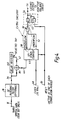
- a more practical autocorrelation block circuit diagram is shown in Figure 2.
- a sampled speech signal is digitised and the sign bit only is input at 16 to a D.C. blocking filter 18.
- the filter 18 may be any conventional high pass filter such as that shown in Figure 5.
- the filter there shown comprises an input 20, a forward feed path 22, a summer 24 whereto are fed input 20 and a feedback signal on a line 26, a delay element 28, a second summer 30 having as inputs the output of the delay element 28 and the forward feed path 22 and providing an output 32 from which is taken the feedback signal, through an amplifier 34 to the line 26.
- the filter 18 strips out any D.C. offset and provides an output 36 which is fed directly to a multiplier 38 (equivalent to the multiplier 3 of Figure 1) and to a delay register 40 (equivalent to the shift register 6 of Figure 1).
- a selectable tap 42 provides a second input to the mixer 38.
- the output 44 of the mixer 38 is fed to an up/down converter 46 clocked at the sampling rate (16KHz) by a clock 48.
- the converter 46 is reset at the end of each correlation period by reset means 50.
- the underflow output 52 of the counter 46 is fed to a latch 54 which is also reset by the reset means 50 to provide an output 56 to inhibit adaptive echo cancellation.
- Figures 3 and 3A show the number of 16KHz delay elements necessary to detect correlation if underflow ( Figure 3) or underflow and overflow (Figure 3A) output of the counter such as the counter 46 is taken.
- underflow representations shows that the number of delay elements required is inversely proportional to the frequency of the sinusoid. If a combination of underflow and overflow (negative or positive and value) is taken then the advantageously low number of delay elements (2) could be used for sinusoids up to 1000Hz and thereafter six (or preferable eight either as a single element or two banks of four) could be used for all frequencies from zero to maximum frequency at which sinusoids cause problems.
- the up/down counter 46 has an overflow output 58 which is fed to one input of an OR gate 60 to the other input of which is fed the underflow 52 from the counter 46.
- the output 62 from the OR gate 60 is fed to the latch 54 and the output 56 is taken and used in the same way as previously.
- the hardware for the correlator circuit of the invention is capable of being built on an integrated circuit chip with only a small increase in the chip area needed over that required for the audio processor including the adaptive echo cancellor. In one embodiment, an area increase of only 3% was required to support the components needed for the correlator circuit.
Landscapes
- Engineering & Computer Science (AREA)
- Physics & Mathematics (AREA)
- General Physics & Mathematics (AREA)
- Mathematical Physics (AREA)
- Computational Mathematics (AREA)
- Theoretical Computer Science (AREA)
- Mathematical Analysis (AREA)
- Mathematical Optimization (AREA)
- Pure & Applied Mathematics (AREA)
- Data Mining & Analysis (AREA)
- Software Systems (AREA)
- Databases & Information Systems (AREA)
- Algebra (AREA)
- General Engineering & Computer Science (AREA)
- Computing Systems (AREA)
- Computer Networks & Wireless Communication (AREA)
- Signal Processing (AREA)
- Cable Transmission Systems, Equalization Of Radio And Reduction Of Echo (AREA)
- Stereo-Broadcasting Methods (AREA)
- Stereophonic System (AREA)
- Input Circuits Of Receivers And Coupling Of Receivers And Audio Equipment (AREA)
- Use Of Switch Circuits For Exchanges And Methods Of Control Of Multiplex Exchanges (AREA)
- Time-Division Multiplex Systems (AREA)
- Compression, Expansion, Code Conversion, And Decoders (AREA)
- Heat-Exchange Devices With Radiators And Conduit Assemblies (AREA)
Claims (10)
- Schaltung zur Audiosignalverarbeitung zum Verarbeiten eines digitalcodierten Eingangssignals, wobei die Schaltung eine Einrichtung zum Abtasten des codierten Signals umfaßt, eine Einrichtung zum Berechnen eines Maßes der Korrelationsfunktion des abgetasteten Signals zu einem weiteren abgetasteten Signal während eines speziellen Zeitrahmens aus den abgetasteten Werten, wobei der Wert dieser Funktion dazu dient, die Operation eines adaptiven Echokompensationsalgorithmus zu steuern, in dem die abgetasteten Signalabschnitte so beschnitten werden, daß nur das arithmetische Vorzeichenbit jedes Signalabschnitts zur Funktionsberechnung beiträgt, derart, daß eine Steuerung für eine Eliminierung unerwünschter Effekte bezüglich des adaptiven Algorithmus erbracht werden kann.
- Schaltung nach Anspruch 1, in welcher das abgetastete digitalcodierte Eingangssignal und das weitere abgetastete Signal dieselben abgetasteten Signale sind, wodurch die Schaltung als Autokorrelator wirkt.
- Schaltung nach Anspruch 1 oder 2, aufweisend eine Einrichtung, die am Ende jedes Zeitrahmens wirkt, zum Steuern der Operation des adaptiven Algorithmus für eine neue Funktionsberechnung.
- Schaltung nach Anspruch 1, 2 oder 3, in welcher der Eingangssignalabtastwert anfangs in einem Extraktionsblock (2) verarbeitet wird, der dazu ausgelegt ist, das für dieses Signal zutreffende arithmetische Vorzeichen zu bestimmen, wobei die resultierenden Vorzeichenbits aufeinanderfolgend einem Schieberegister (6) zugeführt werden, das dazu ausgelegt ist, eine vorbestimmte Anzahl dieser Vorzeichenbits zu speichern.
- Schaltung nach Anspruch 4, welche Ausgangssignale aus selektierten Stellen im Schieberegister gemäß einer Steuerlogik-Selektionsschaltung vorsieht.
- Schaltung nach Anspruch 5, in welcher das Ausgangssignal von der Selektionsschaltung in einem Multiplizierer (3) mit arithmetischen Vorzeichensignalen kombiniert wird, die aus dem Pfad des weiteren abgetasteten Signals extrahiert sind, und ein Multipliziererausgangssignal einem Aufwärts/Abwärts-Zähler (8) zugeführt wird.
- Schaltung nach Anspruch 6, in welcher der Aufwärts/Abwärts-Zähler (8) Unterlauf- und Uberlaufausgangssignale aufweist, die sowohl Vorzeichen- als auch Werte-Ausgangssignale liefern.
- Schaltung nach einem vorhergehenden Anspruch, ferner aufweisend ein Gleichspannungssperrfilter (18).
- Schaltung nach einem vorhergehenden Anspruch, ferner aufweisend eine Latch-Schaltung, die am Ende jeder weiteren Berechnung zurückgesetzt wird, um das arithmetische Vorzeichen und den Wert der Berechnung zur Verhinderung oder zum Zulassen der Operation des adaptiven Echokompensationsalgorithmus zu halten.
- Fernsprecheramtsleitungs-Interfaceschaltung, aufweisend eine Schaltung zur Audiosignalverarbeitung nach einem vorhergehenden Anspruch.
Applications Claiming Priority (3)
| Application Number | Priority Date | Filing Date | Title |
|---|---|---|---|
| GB8910956A GB2232860A (en) | 1989-05-12 | 1989-05-12 | Audio signal echo cancellation circuit |
| GB9010752A GB2232563B (en) | 1989-05-12 | 1990-05-14 | Audio signal processor circuit |
| PCT/GB1990/000747 WO1991018453A1 (en) | 1989-05-12 | 1990-05-15 | Audio signal processor circuit |
Publications (2)
| Publication Number | Publication Date |
|---|---|
| EP0482003A1 EP0482003A1 (de) | 1992-04-29 |
| EP0482003B1 true EP0482003B1 (de) | 1994-12-14 |
Family
ID=27264476
Family Applications (1)
| Application Number | Title | Priority Date | Filing Date |
|---|---|---|---|
| EP90907341A Expired - Lifetime EP0482003B1 (de) | 1989-05-12 | 1990-05-15 | Schaltung zur audiosignalverarbeitung |
Country Status (8)
| Country | Link |
|---|---|
| US (1) | US5453976A (de) |
| EP (1) | EP0482003B1 (de) |
| JP (1) | JPH05501941A (de) |
| AT (1) | ATE115794T1 (de) |
| CA (1) | CA2063800C (de) |
| DE (1) | DE69015193T2 (de) |
| ES (1) | ES2064733T3 (de) |
| WO (1) | WO1991018453A1 (de) |
Families Citing this family (3)
| Publication number | Priority date | Publication date | Assignee | Title |
|---|---|---|---|---|
| DE19543666A1 (de) * | 1995-11-23 | 1997-05-28 | Sel Alcatel Ag | Echokompensator |
| US7054346B2 (en) * | 2001-05-07 | 2006-05-30 | Lucent Technologies Inc. | Enhanced frequency hopping in a wireless system |
| KR101815329B1 (ko) | 2009-12-21 | 2018-01-05 | 달리 시스템즈 씨오. 엘티디. | 변조 방식에 무관한 디지털 하이브리드 모드 전력 증폭기 시스템 및 그 방법 |
Family Cites Families (13)
| Publication number | Priority date | Publication date | Assignee | Title |
|---|---|---|---|---|
| US3732410A (en) * | 1969-12-22 | 1973-05-08 | Postmaster Department Res Labo | Self adaptive filter and control circuit therefor |
| US3789165A (en) * | 1972-04-24 | 1974-01-29 | Communications Satellite Corp | Echo canceller with variable threshold |
| US4024358A (en) * | 1975-10-31 | 1977-05-17 | Communications Satellite Corporation (Comsat) | Adaptive echo canceller using differential pulse code modulation encoding |
| US4071903A (en) * | 1976-08-04 | 1978-01-31 | International Business Machines Corporation | Autocorrelation function factor generating method and circuitry therefor |
| NL7902053A (nl) * | 1979-03-15 | 1980-09-17 | Philips Nv | Echocompensator voor homochrone data overdrachtssyste- men. |
| US4270026A (en) * | 1979-11-28 | 1981-05-26 | International Telephone And Telegraph Corporation | Interpolator apparatus for increasing the word rate of a digital signal of the type employed in digital telephone systems |
| DE3235915T1 (de) * | 1981-03-05 | 1983-11-17 | Western Electric Co., Inc., 10038 New York, N.Y. | Energiebanddiskriminator |
| US4621172A (en) * | 1982-12-22 | 1986-11-04 | Nec Corporation | Fast convergence method and system for echo canceller |
| FR2538975A1 (fr) * | 1982-12-30 | 1984-07-06 | Trt Telecom Radio Electr | Procede utilise dans un dispositif d'annulation d'echo pour la mesure d'un retard d'echo et dispositif de mise en oeuvre de ce procede |
| US4562312A (en) * | 1983-02-17 | 1985-12-31 | At&T Bell Laboratories | Subsampling delay estimator for an echo canceler |
| US4707824A (en) * | 1983-12-15 | 1987-11-17 | Nec Corporation | Method and apparatus for cancelling echo |
| US4760596A (en) * | 1986-02-25 | 1988-07-26 | Gte Laboratories Incorporated | Adaptive echo cancellation and equalization system signal processor and method therefor |
| US5062102A (en) * | 1988-12-01 | 1991-10-29 | Nec Corporation | Echo canceller with means for determining filter coefficients from autocorrelation and cross-correlation coefficients |
-
1990
- 1990-05-15 WO PCT/GB1990/000747 patent/WO1991018453A1/en not_active Ceased
- 1990-05-15 EP EP90907341A patent/EP0482003B1/de not_active Expired - Lifetime
- 1990-05-15 ES ES90907341T patent/ES2064733T3/es not_active Expired - Lifetime
- 1990-05-15 JP JP2507405A patent/JPH05501941A/ja active Pending
- 1990-05-15 US US07/793,399 patent/US5453976A/en not_active Expired - Fee Related
- 1990-05-15 AT AT90907341T patent/ATE115794T1/de active
- 1990-05-15 CA CA002063800A patent/CA2063800C/en not_active Expired - Fee Related
- 1990-05-15 DE DE69015193T patent/DE69015193T2/de not_active Expired - Fee Related
Also Published As
| Publication number | Publication date |
|---|---|
| ES2064733T3 (es) | 1995-02-01 |
| EP0482003A1 (de) | 1992-04-29 |
| DE69015193T2 (de) | 1995-05-04 |
| US5453976A (en) | 1995-09-26 |
| WO1991018453A1 (en) | 1991-11-28 |
| CA2063800C (en) | 2001-07-03 |
| DE69015193D1 (de) | 1995-01-26 |
| CA2063800A1 (en) | 1991-11-16 |
| ATE115794T1 (de) | 1994-12-15 |
| JPH05501941A (ja) | 1993-04-08 |
Similar Documents
| Publication | Publication Date | Title |
|---|---|---|
| EP0008160B1 (de) | Programmierbarer digitaler Detektor für tonfrequente Signale | |
| US4823382A (en) | Echo canceller with dynamically positioned adaptive filter taps | |
| Zoraster | Minimum peak range sidelobe filters for binary phase-coded waveforms | |
| US4351983A (en) | Speech detector with variable threshold | |
| CN86106498A (zh) | 数字信号处理器中的自动增益控制 | |
| JPS62135784A (ja) | パルス妨害検出装置及び方法 | |
| US5465405A (en) | Apparatus and method for detecting signals | |
| EP0584912A1 (de) | Empfänger mit Verwendung eines angepassten Filters und eines Mittelwertfilters | |
| EP0482003B1 (de) | Schaltung zur audiosignalverarbeitung | |
| US5793820A (en) | Automatic adaptive filtering according to frequency modulation rate | |
| GB2232563A (en) | Audio signal echo cancellation circuit | |
| EP0009488B1 (de) | Vorrichtung zum messen des verhältnisses zwischen einer anzahl von aufeinander folgender zustände einer ersten und zweiten serie von zuständen | |
| CA1192315A (en) | Systolic computational array | |
| KR0153122B1 (ko) | 오디오 신호 프로세서 회로 | |
| JP3578793B2 (ja) | Iirゴースト打消しシステム | |
| US4490831A (en) | Digital pulse detector circuit having selectable false alarm rate | |
| Roberts | On the detection of a signal known except for phase | |
| CA2037484C (en) | Method and circuit arrangement for level monitoring | |
| Murakami et al. | Recursive FIR digital filter design using a z-transform on a finite ring | |
| KR940012909A (ko) | 전송 시스템 | |
| Grassmann | The optimal estimation of the expected number in a M/D/∞ queueing system | |
| SU980271A2 (ru) | Селектор импульсов по длительности | |
| Czarnecki et al. | Approximation of locally optimum detector nonlinearities (Corresp.) | |
| GB2330744A (en) | Using DSP to control telephone howling attenuation | |
| SU1166135A1 (ru) | Устройство дл вычислени структурной и интервальной функций |
Legal Events
| Date | Code | Title | Description |
|---|---|---|---|
| PUAI | Public reference made under article 153(3) epc to a published international application that has entered the european phase |
Free format text: ORIGINAL CODE: 0009012 |
|
| AK | Designated contracting states |
Kind code of ref document: A1 Designated state(s): AT BE CH DE DK ES FR IT LI LU NL SE |
|
| 17P | Request for examination filed |
Effective date: 19920528 |
|
| 17Q | First examination report despatched |
Effective date: 19931217 |
|
| RAP1 | Party data changed (applicant data changed or rights of an application transferred) |
Owner name: GPT LIMITED Owner name: PLESSEY SEMICONDUCTORS LIMITED |
|
| GRAA | (expected) grant |
Free format text: ORIGINAL CODE: 0009210 |
|
| AK | Designated contracting states |
Kind code of ref document: B1 Designated state(s): AT BE CH DE DK ES FR IT LI LU NL SE |
|
| PG25 | Lapsed in a contracting state [announced via postgrant information from national office to epo] |
Ref country code: LI Effective date: 19941214 Ref country code: DK Effective date: 19941214 Ref country code: CH Effective date: 19941214 |
|
| REF | Corresponds to: |
Ref document number: 115794 Country of ref document: AT Date of ref document: 19941215 Kind code of ref document: T |
|
| ET | Fr: translation filed | ||
| REF | Corresponds to: |
Ref document number: 69015193 Country of ref document: DE Date of ref document: 19950126 |
|
| EAL | Se: european patent in force in sweden |
Ref document number: 90907341.3 |
|
| REG | Reference to a national code |
Ref country code: ES Ref legal event code: FG2A Ref document number: 2064733 Country of ref document: ES Kind code of ref document: T3 |
|
| ITF | It: translation for a ep patent filed | ||
| REG | Reference to a national code |
Ref country code: CH Ref legal event code: PL |
|
| PG25 | Lapsed in a contracting state [announced via postgrant information from national office to epo] |
Ref country code: LU Free format text: LAPSE BECAUSE OF NON-PAYMENT OF DUE FEES Effective date: 19950531 |
|
| PLBE | No opposition filed within time limit |
Free format text: ORIGINAL CODE: 0009261 |
|
| STAA | Information on the status of an ep patent application or granted ep patent |
Free format text: STATUS: NO OPPOSITION FILED WITHIN TIME LIMIT |
|
| 26N | No opposition filed | ||
| PGFP | Annual fee paid to national office [announced via postgrant information from national office to epo] |
Ref country code: SE Payment date: 19990414 Year of fee payment: 10 |
|
| PGFP | Annual fee paid to national office [announced via postgrant information from national office to epo] |
Ref country code: AT Payment date: 19990512 Year of fee payment: 10 |
|
| PGFP | Annual fee paid to national office [announced via postgrant information from national office to epo] |
Ref country code: ES Payment date: 19990524 Year of fee payment: 10 |
|
| PGFP | Annual fee paid to national office [announced via postgrant information from national office to epo] |
Ref country code: NL Payment date: 19990531 Year of fee payment: 10 |
|
| PGFP | Annual fee paid to national office [announced via postgrant information from national office to epo] |
Ref country code: BE Payment date: 19990728 Year of fee payment: 10 |
|
| PG25 | Lapsed in a contracting state [announced via postgrant information from national office to epo] |
Ref country code: AT Free format text: LAPSE BECAUSE OF NON-PAYMENT OF DUE FEES Effective date: 20000515 |
|
| PG25 | Lapsed in a contracting state [announced via postgrant information from national office to epo] |
Ref country code: SE Free format text: LAPSE BECAUSE OF NON-PAYMENT OF DUE FEES Effective date: 20000516 Ref country code: ES Free format text: THE PATENT HAS BEEN ANNULLED BY A DECISION OF A NATIONAL AUTHORITY Effective date: 20000516 |
|
| PG25 | Lapsed in a contracting state [announced via postgrant information from national office to epo] |
Ref country code: BE Free format text: LAPSE BECAUSE OF NON-PAYMENT OF DUE FEES Effective date: 20000531 |
|
| BERE | Be: lapsed |
Owner name: GPT LTD Effective date: 20000531 Owner name: MITEL SEMICONDUCTOR LTD Effective date: 20000531 |
|
| PG25 | Lapsed in a contracting state [announced via postgrant information from national office to epo] |
Ref country code: NL Free format text: LAPSE BECAUSE OF NON-PAYMENT OF DUE FEES Effective date: 20001201 |
|
| EUG | Se: european patent has lapsed |
Ref document number: 90907341.3 |
|
| NLV4 | Nl: lapsed or anulled due to non-payment of the annual fee |
Effective date: 20001201 |
|
| REG | Reference to a national code |
Ref country code: ES Ref legal event code: FD2A Effective date: 20020304 |
|
| PGFP | Annual fee paid to national office [announced via postgrant information from national office to epo] |
Ref country code: FR Payment date: 20020508 Year of fee payment: 13 |
|
| PGFP | Annual fee paid to national office [announced via postgrant information from national office to epo] |
Ref country code: DE Payment date: 20020522 Year of fee payment: 13 |
|
| PG25 | Lapsed in a contracting state [announced via postgrant information from national office to epo] |
Ref country code: DE Free format text: LAPSE BECAUSE OF NON-PAYMENT OF DUE FEES Effective date: 20031202 |
|
| PG25 | Lapsed in a contracting state [announced via postgrant information from national office to epo] |
Ref country code: FR Free format text: LAPSE BECAUSE OF NON-PAYMENT OF DUE FEES Effective date: 20040130 |
|
| REG | Reference to a national code |
Ref country code: FR Ref legal event code: ST |
|
| PG25 | Lapsed in a contracting state [announced via postgrant information from national office to epo] |
Ref country code: IT Free format text: LAPSE BECAUSE OF NON-PAYMENT OF DUE FEES;WARNING: LAPSES OF ITALIAN PATENTS WITH EFFECTIVE DATE BEFORE 2007 MAY HAVE OCCURRED AT ANY TIME BEFORE 2007. THE CORRECT EFFECTIVE DATE MAY BE DIFFERENT FROM THE ONE RECORDED. Effective date: 20050515 |