EP0481691B1 - Ultraschall-Doppler-Durchflussmesser mit Diskriminierung der Gewebebewegung - Google Patents
Ultraschall-Doppler-Durchflussmesser mit Diskriminierung der Gewebebewegung Download PDFInfo
- Publication number
- EP0481691B1 EP0481691B1 EP91309373A EP91309373A EP0481691B1 EP 0481691 B1 EP0481691 B1 EP 0481691B1 EP 91309373 A EP91309373 A EP 91309373A EP 91309373 A EP91309373 A EP 91309373A EP 0481691 B1 EP0481691 B1 EP 0481691B1
- Authority
- EP
- European Patent Office
- Prior art keywords
- doppler
- tissue
- information signals
- signals
- motion
- Prior art date
- Legal status (The legal status is an assumption and is not a legal conclusion. Google has not performed a legal analysis and makes no representation as to the accuracy of the status listed.)
- Expired - Lifetime
Links
Images


Classifications
-
- A—HUMAN NECESSITIES
- A61—MEDICAL OR VETERINARY SCIENCE; HYGIENE
- A61B—DIAGNOSIS; SURGERY; IDENTIFICATION
- A61B8/00—Diagnosis using ultrasonic, sonic or infrasonic waves
- A61B8/06—Measuring blood flow
-
- G—PHYSICS
- G01—MEASURING; TESTING
- G01F—MEASURING VOLUME, VOLUME FLOW, MASS FLOW OR LIQUID LEVEL; METERING BY VOLUME
- G01F1/00—Measuring the volume flow or mass flow of fluid or fluent solid material wherein the fluid passes through a meter in a continuous flow
- G01F1/66—Measuring the volume flow or mass flow of fluid or fluent solid material wherein the fluid passes through a meter in a continuous flow by measuring frequency, phase shift or propagation time of electromagnetic or other waves, e.g. using ultrasonic flowmeters
- G01F1/663—Measuring the volume flow or mass flow of fluid or fluent solid material wherein the fluid passes through a meter in a continuous flow by measuring frequency, phase shift or propagation time of electromagnetic or other waves, e.g. using ultrasonic flowmeters by measuring Doppler frequency shift
-
- G—PHYSICS
- G01—MEASURING; TESTING
- G01P—MEASURING LINEAR OR ANGULAR SPEED, ACCELERATION, DECELERATION, OR SHOCK; INDICATING PRESENCE, ABSENCE, OR DIRECTION, OF MOVEMENT
- G01P5/00—Measuring speed of fluids, e.g. of air stream; Measuring speed of bodies relative to fluids, e.g. of ship, of aircraft
- G01P5/24—Measuring speed of fluids, e.g. of air stream; Measuring speed of bodies relative to fluids, e.g. of ship, of aircraft by measuring the direct influence of the streaming fluid on the properties of a detecting acoustical wave
- G01P5/241—Measuring speed of fluids, e.g. of air stream; Measuring speed of bodies relative to fluids, e.g. of ship, of aircraft by measuring the direct influence of the streaming fluid on the properties of a detecting acoustical wave by using reflection of acoustical waves, i.e. Doppler-effect
-
- G—PHYSICS
- G01—MEASURING; TESTING
- G01S—RADIO DIRECTION-FINDING; RADIO NAVIGATION; DETERMINING DISTANCE OR VELOCITY BY USE OF RADIO WAVES; LOCATING OR PRESENCE-DETECTING BY USE OF THE REFLECTION OR RERADIATION OF RADIO WAVES; ANALOGOUS ARRANGEMENTS USING OTHER WAVES
- G01S15/00—Systems using the reflection or reradiation of acoustic waves, e.g. sonar systems
- G01S15/02—Systems using the reflection or reradiation of acoustic waves, e.g. sonar systems using reflection of acoustic waves
- G01S15/50—Systems of measurement, based on relative movement of the target
- G01S15/52—Discriminating between fixed and moving objects or between objects moving at different speeds
-
- G—PHYSICS
- G01—MEASURING; TESTING
- G01S—RADIO DIRECTION-FINDING; RADIO NAVIGATION; DETERMINING DISTANCE OR VELOCITY BY USE OF RADIO WAVES; LOCATING OR PRESENCE-DETECTING BY USE OF THE REFLECTION OR RERADIATION OF RADIO WAVES; ANALOGOUS ARRANGEMENTS USING OTHER WAVES
- G01S15/00—Systems using the reflection or reradiation of acoustic waves, e.g. sonar systems
- G01S15/02—Systems using the reflection or reradiation of acoustic waves, e.g. sonar systems using reflection of acoustic waves
- G01S15/50—Systems of measurement, based on relative movement of the target
- G01S15/58—Velocity or trajectory determination systems; Sense-of-movement determination systems
- G01S15/582—Velocity or trajectory determination systems; Sense-of-movement determination systems using transmission of interrupted pulse-modulated waves and based upon the Doppler effect resulting from movement of targets
-
- G—PHYSICS
- G01—MEASURING; TESTING
- G01S—RADIO DIRECTION-FINDING; RADIO NAVIGATION; DETERMINING DISTANCE OR VELOCITY BY USE OF RADIO WAVES; LOCATING OR PRESENCE-DETECTING BY USE OF THE REFLECTION OR RERADIATION OF RADIO WAVES; ANALOGOUS ARRANGEMENTS USING OTHER WAVES
- G01S15/00—Systems using the reflection or reradiation of acoustic waves, e.g. sonar systems
- G01S15/88—Sonar systems specially adapted for specific applications
- G01S15/89—Sonar systems specially adapted for specific applications for mapping or imaging
- G01S15/8906—Short-range imaging systems; Acoustic microscope systems using pulse-echo techniques
- G01S15/8979—Combined Doppler and pulse-echo imaging systems
- G01S15/8981—Discriminating between fixed and moving objects or between objects moving at different speeds, e.g. wall clutter filter
Definitions
- This invention relates to ultrasonic diagnostic systems which measure the flow of fluids through Doppler interrogation and, in particular, to the discrimination of tissue motion by such systems.
- Ultrasonic diagnostic systems which measure the flow of fluids through Doppler interrogation are in widespread use for the acquisition of medical patient data concerning the flow of blood and other fluids in the body.
- an area of the body such as the heart is repetitively interrogated with ultrasonic waves and returning echo signals are compared to a reference to determine the velocity of blood flow in the heart.
- This interrogation is performed over a two-dimensional sector of the heart to determine flow velocities throughout the interrogated area.
- the resultant flow velocity values are then displayed in a color image format as a function of measurement location, where different shades and intensities of color represent blood flow of different velocities and directions.
- Such systems are commercially available as what are known as ultrasonic color flow imaging systems.
- Doppler systems operate by measuring velocity in terms of relative motion between the fluids being interrogated and the scanhead which produces the ultrasonic waves and detects the resultant echo signals.
- Doppler information signals are returned not only by fluids, but also by tissue structure within the body. These latter signal components are undesired in systems where only fluid motion is being interrogated.
- the prior art systems perform well when the scanhead is held stationary and the only substance moving in the interrogated area is the fluid which is being measured. This is because techniques are known for removing signal components returned from stationary tissue, and are generally embodied in what are referred to as clutter rejection filters.
- US-A-4 651 745 describes an ultrasonic diagnostic device for measuring the velocity of blood flow within a living body, wherein a received signal is amplified using a logarithmic amplification characteristic.
- a filter is provided to eliminate signals resulting from the wall of the blood vessel.
- an ultrasonic diagnostic system as defined by claim 9.
- an ultrasonic diagnostic system as defined by claim 15.
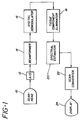
- an ultrasonic diagnostic system for measuring the flow rates of fluids in the body of a patient and constructed in accordance with the principles of the present invention is shown in block diagram form.
- a scanhead 10 containing one or more piezoelectric transducer elements transmits ultrasonic waves into the body of a patient and receives ultrasonic echoes returned by the tissue and fluid structures of the body. The returning echoes are converted to electrical signals by the transducer(s) and the signals are then digitized by an analog to digital converter 12.
- a plurality of such digital signal samples are combined in a beamformer 14 to form coherent ultrasonic information signals which are coupled to a digital demodulator 16.
- the fluid flow velocity information contained in the ultrasonic information signals is encoded as phase shifts of the returning echo signals in relation to a reference signal. Accordingly the demodulation process involves a translation of the ultrasonic information signals to an intermediate frequency range and the resolution of the phase information into two components, an in-phase (I) component and a quadrature (Q) component.
- the output of the digital demodulator 16 thus is a stream of corresponding I and Q phase information signals containing information as to the velocity of fluids and tissue in the patient's body.
- the phase information signals are applied to a tissue component eliminator 18.
- the tissue component eliminator processes the signals by discriminating signal components representing the motion of tissue relative to the scanhead 10, and eliminating these components from the Doppler spectrum. I and Q velocity information signals from which the effects of tissue motion have been removed are produced at the output of the tissue component eliminator.
- the I and Q information signals from which the tissue signal components have been removed are applied to a spectral estimator 20, which determines the fluid velocities as represented by the Doppler content of the signals.
- the velocity information signals produced by the spectral estimator 20 are then applied to a scan converter where, in a preferred embodiment, the velocity information is translated to a color and an intensity and stored locationally as a function of the position in the scanned area of the body at which the measurement was taken.
- the scan converter thus arranges the flow velocities in an image format suitable for a color flow image, and the image is then displayed on an image display 24.
- Other image formats such as numerical and graphical representations may also be employed to display the flow velocities to the user.
- FIGURE 2 depicts the manner in which Doppler data may be acquired to form a color flow image.
- the scanhead 10 sequentially transmits ultrasonic pulses in a plurality of vector directions over the scanned area 26 of the patient's body. One of these vector directions is indicated by arrow V n in FIGURE 2.
- V n One of these vector directions is indicated by arrow V n in FIGURE 2.
- signal samples are taken from echoes returning from sequential positions along the vector. These positions are referred to herein as range cells, some of which are labelled C1, C2, C3, ... C n in the FIGURE.
- the signal samples are processed by the beamformer 14 and converted by the digital demodulator 16 to I and Q quadrature signal samples.
- This sequence of pulse transmission and echo reception is repeated a number of times along vector direction V n .
- the transmitted pulses of four of these sequences are labelled P1, P2, P3, and P4 in the chart of FIGURE 3.
- the I,Q echo samples taken in response to each of these pulse transmissions are shown below each pulse in FIGURE 3.
- Each horizontal row of I,Q samples in FIGURE 3 thus represents signal samples taken at a particular range cell location C1 ... C n , but at different points in time.
- An array of data of the form illustrated in FIGURE 3 is operated upon by the tissue component eliminator 18 to remove the effects of tissue motion from the signals.
- the Doppler velocity information content of the I,Q signal samples may be understood by reference to a representative Doppler spectrum as shown in FIGURE 4a.
- This spectrum is shown as bounded by end points -PRF/2 and +PRF/2 although as will be subsequently explained the spectrum is a continuum through these end points.
- the end points -PRF/2 and +PRF/2 are the Nyquist limits of the signal sampling rate at a particular range cell, the sampling rate being the pulse repetition freguency (PRF) of pulses P1, P2, P3, etc. of FIGURE 3.
- PRF pulse repetition freguency
- In the center of the spectrum is DC, or zero, the Doppler frequency of tissue and fluids at rest.
- the Doppler phase information contained in the I,Q samples increases in the positive sense (+ ⁇ ) or negative sense (- ⁇ ) toward the limit values from zero, depending on the velocity of the material at the range cell and its direction.
- the waveform of FIGURE 4a is seen to contain two peaks, a major one 30 and a lesser one 32.
- the major peak 30 results from echo information returned by tissue and the minor peak 32 results from echo information returned by a fluid such as blood.
- Peak 30 may be as much as 60-80 dB greater than peak 32 because tissue is a much stronger reflector of ultrasonic waves than blood.
- peak 30 is located at zero, a condition that exists when the reflecting tissue is substantially at rest, that is, there is substantially no motion component from the tissue.
- Elimination of the spectral components of peak 30 may be accomplished by high pass filtering the signals of the waveform of FIGURE 4a, as the skirts of the rejection band defined by the high pass filter will be displaced symmetrically about zero, the frequency about which the signal components of peak 30 resulting from substantially stationary tissue are displaced.
- This known technique is in current use, as conventional color flow systems have a need to eliminate signals returned by stationary structures prior to operating on the Doppler flow content of the signals. Signal components resulting from substantially stationary tissue structure are not within the definition of "tissue motion components" as that term is used herein.
- FIGURE 4b The problem confronted by the present invention is spectrally represented by FIGURE 4b.
- moving tissue has generated the signal components comprising peak 30′.
- FIGURE 4b differs from FIGURE 4a in that the peak 30′ is displaced from zero by reason of the motion of the tissue.
- the blood velocity peak 32 is displaced on the opposite side of the zero reference by approximately the same magnitude as the displacement of peak 30′.
- An effort to remove the signal components comprising peak 30′, as by notch or high pass filtering, would also eliminate the signal components comprising the blood velocity peak 32 by reason of the spectrally symmetrical effect of the filter.
- a process premised on the assumption that the tissue component is closer to zero than the blood flow component is ineffective in dealing with tissue motion in this situation.
- FIGURES 5a-5d A technique for overcoming this problem in accordance with the principles of the present invention is illustrated by the spectra of FIGURES 5a-5d.
- the frequency location ⁇ t of the tissue motion component 30′ in FIGURE 5a is determined.
- the signals of the entire Doppler spectrum are modulated by the frequency deviation of the tissue component such that the tissue motion component becomes located at zero, as shown in FIGURE 5b. Due to the continuity of the spectrum through the positive and negative Nyquist limits, this spectral shift of the signal components results in a "wrap around" of a portion of the spectral content.
- the blood flow component 32 of FIGURE 5a is wrapped around +PRF/2 and through -PRF/2 so that the blood flow component appears at the left side of the spectrum in FIGURE 5b after modulation.
- the spectral data is high pass filtered to remove the tissue component.
- the skirts 34, 34′ of the high pass filter are shown in FIGURE 5c, and the spectral content between the skirts as shown in dotted lines is effectively notched out of the spectrum.
- the spectral data is remodulated to relocate the blood flow component at its original spectral position. This is accomplished by remodulating the signals by the same deviation ⁇ t used above in FIGURE 5b, but in an opposite sense.
- the original modulation was by the deviation + ⁇ t
- the remodulation is by the value - ⁇ t .
- the spectral result of this remodulation is shown in FIGURE 5d.
- Digital apparatus for performing the inventive technique for eliminating the effects of tissue motion may be constructed to operate upon digital I,Q signal data in the following manner.
- a number of known digital techniques may be used to discriminate the location of the tissue component, a preferred one being an autocorrelator.
- This autocorrelator operates by creating an offset alignment of the I,Q samples from the range cell location being investigated with the complex conjugate of itself.
- the offset alignment would appear as: Vertically aligned samples are multiplied together and the products aggregated to form a result of the complex form I' + jQ' Using this complex result the arc tangent is calculated using Q'/I', and the result is the frequency of the tissue motion component expressed in radians, the angle ⁇ t .
- FIGURE 6 shows a phase diagram on which the complex value I' + jQ' is indicated, and the tissue component frequency - ⁇ t for the example of FIGURE 5a.
- the left-hand end of the abcissa of the diagram is equal to both +PRF/2 and -PRF/2, the end limits of the linearly drawn spectra discussed previously.
- the spectral data is modulated to shift the tissue motion component to zero by multiplying the I,Q data of the range cell location by a sampled complex sinusoid. This is done by multiplying the I,Q data of the cell by the complex expression cos ⁇ + jsin ⁇ , where ⁇ is equal to + ⁇ t determined by the correlator above.
- a high pass digital filter a preferred one of which is the infinite impulse response (IIR) high pass filter diagrammatically shown in FIGURE 7.
- IIR infinite impulse response
- the input data to the IIR filter is applied at the input x(n), and the filtered data is produced at the output y(n).
- the a and b terms designate multiplying coefficients by which the data values are multiplied in determination of the filter response characteristics
- Z ⁇ 1 indicates a single time interval shift delay
- the dotted nodes are points at which data arriving from two paths of the filter are summed.
- the exact characteristics of the high pass filter cutoff are application dependent, in consideration of the extent of the expected motion artifact.
- the data is remodulated in the same way it was modulated, but using a frequency of the opposite sense as above in the complex sinusoid expression. That is, + ⁇ t is replaced by - ⁇ t , or the reverse, as appropriate.
- the spectral signal content is thereby shifted back to its original frequency domain location but with the effects of tissue motion removed.
- the accuracy of received Doppler information can vary from time to time as a result of random scattering effects and other factors. Such inaccuracies can result in the imprecise determination of the frequency location of the tissue motion component for a particular range cell.
- the present inventors have further found that, on the average, there is only a small deviation in the frequency location of the tissue component from one range cell to an adjacent range cell. The present inventors have taken advantage of this latter finding to overcome the aforementioned problem of tissue component locational inaccuracies.
- the discrimination of tissue component location is accomplished by first determining the complex value I′ +jQ′ of the I,Q data from a number of neighboring range cells.
- I′ + jQ′ can be determined for each of range cells C1-C4 in FIGURE 3.
- the complex values are then accumulated in a summation of the form I′ (sum) + jQ′ (sum) and this accumulated complex value is then used in the arc tangent calculation to determine ⁇ t for one or more of cells C1-C4.
- the correlation of tissue component location between neighboring range cells is utilized to resolve inaccuracies in Doppler signals at particular range cell locations.
- Another problem that may be encountered in an implementation of the present invention is the reception of signal components containing only desired flow information, devoid of any tissue component contamination. Such information reception may occur, for instance, when the range cell is at the center of a chamber of the heart, where only blood flow is present. This condition is spectrally represented in FIGURE 8. In such a case it may be desirable to inhibit operation of a system of the present invention, and it would certainly be desirable not to eliminate the blood flow component as though it were a tissue component.
- the present inventors have made use of their recognition of the disparity in characteristics between tissue motion components and fluid flow components (e.g., signal strength, bandwidth) in applying a threshhold comparison before inplementation of the technique of the present invention. As illustrated in FIGURE 8, when the components of the spectrum do not exceed the threshhold, the inventive system is inhibited so that the blood flow component 32 is not inadvertently removed from the spectrum.
- a preferred technique for implementing this threshhold comparison is to measure the power content of the Doppler spectrum. This may be accomplished digitally by integrating the received data values to effectively find the area under the curve containing the Doppler components. In FIGURE 9, this area is shown by the diagonal lines under the spectral curve. The measured magnitude of the area is compared with a threshhold value and if the value is not exceeded, the tissue component eliminator is inhibited from removing any spectral signal content.
- FIGURE 10 A digital embodiment which provides all of the above features is shown in block diagram form in FIGURE 10.
- an autocorrelator 40 is used to determine ⁇ t , and to determine spectral power.
- the spectral power value is compared with a threshhold value by the comparator 44, and the outcome of the comparison is used to open or close switch 42, controlling the frequency deviation ⁇ t by which the signals are modulated and remodulated. If the result of the comparison indicates that a tissue component is present, resulting either from moving or stationary tissue, switch 42 is closed and the frequency deviation of the tissue component ⁇ t is applied to complex modulator 46 to shift the spectrum, and to complex modulator 50 to shift the spectrum back after the tissue component has been eliminated.
- the complex modulator 50 receives a modulation value of the opposite sense as modulator 46 by reason of the inverting component 52.
- This technique is effective for removing both moving and stationary tissue components, as tissue motion components will be shifted in accordance with their deviation ⁇ t , as will stationary tissue components for which ⁇ t will be found to be zero.
- the spectrum of FIGURE 8 for instance, switch 42 is opened and the modulators 46 and 50 are effectively receiving modulating values of zero.
- the incoming data is shifted by a deviation of zero; that is, no shift is effected.
- the high pass filter 48 will filter the data as above, removing signal content about zero, but this will not adversely affect the outcome of the process as the effect is only to remove zero velocity (no flow) information.
- Modulator 50 will then remodulate the data by zero and the unaffected non-zero velocity flow information 32 is produced at the output for further processing.
- data at the zero (no flow) location is represented in black, a representation which is unaffected by the elimination of data from this spectral location in FIGURE 8.
Landscapes
- Physics & Mathematics (AREA)
- Engineering & Computer Science (AREA)
- Radar, Positioning & Navigation (AREA)
- Remote Sensing (AREA)
- General Physics & Mathematics (AREA)
- Acoustics & Sound (AREA)
- Health & Medical Sciences (AREA)
- Life Sciences & Earth Sciences (AREA)
- Computer Networks & Wireless Communication (AREA)
- Biophysics (AREA)
- Biomedical Technology (AREA)
- Multimedia (AREA)
- Hematology (AREA)
- Fluid Mechanics (AREA)
- Electromagnetism (AREA)
- Nuclear Medicine, Radiotherapy & Molecular Imaging (AREA)
- Pathology (AREA)
- Radiology & Medical Imaging (AREA)
- Aviation & Aerospace Engineering (AREA)
- Heart & Thoracic Surgery (AREA)
- Medical Informatics (AREA)
- Molecular Biology (AREA)
- Surgery (AREA)
- Animal Behavior & Ethology (AREA)
- General Health & Medical Sciences (AREA)
- Public Health (AREA)
- Veterinary Medicine (AREA)
- Ultra Sonic Daignosis Equipment (AREA)
- Measuring Pulse, Heart Rate, Blood Pressure Or Blood Flow (AREA)
Claims (16)
- Verfahren zum Entfernen von Effekten einer Gewebebewegung von Doppler-Geschwindigkeits-Informationssignalen, welche Signalkomponenten von im wesentlichen stationärem Gewebe und/oder Komponenten von Gewebebewegungen beinhalten können, umfassend die Schritte eines:a) Demodulierens der empfangenen Doppler-Informationssignale zur Erzeugung von demodulierten Doppler-Informationssignalen, dadurch gekennzeichnet, daß das Verfahren zusätzlich die Schritte umfaßt:b) Diskriminieren der demodulierten Doppler-Informationssignale für Signalkomponenten der Gewebehewegung vor dem Formatieren der Doppler-Geschwindigkeits-Informationssignale für eine Anzeige;c) Eliminieren der Signalkomponenten der Gewehehewegung von den diskriminierten Signalen; undd) Bereitstellen von Geschwindgkeits-Informationssignalen, von welchen die Effekte einer Gewebebewegung entfernt wurden.
- Verfahren nach Anspruch 1, worin Schritt b) weiters den Schritt einer Bestimmung der Doppler-Frequenz der Signalkomponenten der Gewebebewegung umfaßt.
- Verfahren nach Anspruch 1 oder Anspruch 2, worin Schritt c) weiters den Schritt eines Filterns von Signalen, welche Doppler-Informationen enthalten, mit Hilfe eines Filters umfaßt, welches ein Sperrband bei der Doppler-Frequenz der diskriminierten Signalkomponenten der Gewebebewegung aufweist.
- Verfahren nach einem der vorangehenden Ansprüche, worin Schritt c) den Schritt eines Verschiebens der diskriminierten Signalkomponenten der Gewebebewegung zu einem vorbestimmten Doppler-Frequenzband und eines Filterns der Signale, welche die Doppler-Information enthalten, mit Hilfe eines Filters umfaßt, welches ein Sperrband entsprechend dem vorbestimmten Doppler-Frequenzband aufweist.
- Verfahren nach einem der vorangehenden Ansprüche, welches weiters den Schritt eines e) Formatierens der Geschwindigkeits-Informationssignale umfaßt, von welchen Effekte der Gewebebewegung durch Eingabe von Information entsprechend der Geschwindigkeits-Information in ein Bildfeld entfernt wurden.
- Verfahren nach einem der Ansprüche 1 bis 4, worin Schritt c) der Schritt eines e) Bestimmens der Intensität der Doppler-Informationssignale und Unterdrückens des Vorganges des Schrittes c) vorangestellt wird, wenn die Intensität des Doppler-Informationssignals ein vorbestimmtes Kennzeichens nicht übersteigt.
- Verfahren nach Anspruch 6, worin Schritt e) ein Messen der Stärke der Signale im Doppler-Spektrum und ein Unterdrücken des Vorganges des Schrittes c) umfaßt, wenn die gemessene Stärke einen vorbestimmten Schwellwert nicht übersteigt.
- Verfahren nach einem der vorangehenden Ansprüche, worin Schritt b) den Schritt eines Diskriminierens von Signalen, welche Doppler-Information enthalten, umfaßt, welche Signale von einer Mehrzahl von räumlich zueinander in Verbindung stehenden Stellen für Signalkomponenten der Gewebebewegung vor dem Formatieren der poppler-Fluidgeschwindigkeit-Information für eine Anzeige abgeleitet werden.
- Ultraschall-Diagnosesystem zur Verarbeitung von Doppler-Informationssignalen, umfassend:
Mittel (10) zum Empfangen von Fluidbewegung-Doppler-Informationssignalen, welche mit Komponenten von im wesentlichen stationärem Gewebe und/oder Komponenten einer Gewebebewegung kontaminiert sein können;
Mittel (16) zum Demodulieren der empfangenen Doppler-Informationssignale, um demodulierte Doppler-Informationssignale zu erzeugen; dadurch gekennzeichnet, daß das System weiters umfaßt:
Mittel (40, 42, 44) zum Diskriminieren des Vorhandenseins der Komponenten der Gewebebewegung in den demodulierten Doppler-Informationssignalen;
Mittel (46, 48, 50) zum Entfernen der diskriminierten Komponenten der Gewebebewegung;
Mittel (22) zum Erzeugen der Fluidbewegung-Doppler-Informationssignale, aus welchen Komponenten der Gewebebewegung entfernt wurden, um ein Bildformat zur Verfügung zu stellen, welches eine Fluidgeschwindigkeits-Information enthält; und Mittel (24) zur Anzeige der Fluidgeschwindigkeits-Information. - Ultraschall-Diagnosesystem nach Anspruch 9, worin die Demodulationsmittel (16) Phasendemodulationsmittel umfassen und die Mittel zum Diskriminieren (40) weiters Mittel zum Identifizieren der Doppler-Frequenzposition der Komponenten der Gewebebewegung umfassen.
- Ultraschall-Diagnosesystem nach Anspruch 9 oder Anspruch 10, worin die Mittel zum Entfernen Mittel (48) zum Filtern von Doppler-Informationssignalen umfassen, welche ein Sperrband entsprechend den Komponenten der Gewebebewegung aufweisen.
- Ultraschall-Diagnosesystem nach Anspruch 9 oder Anspruch 10, worin die Mittel zum Entfernen erste Mittel (46) zum Verschieben der Komponenten der Gewebebewegung auf eine vorbestimmte Doppler-Frequenzposition und Mittel (48) zum Filtern von Doppler-Informationssignalen umfassen, welche ein Sperrband entsprechend der vorbestimmten Doppler-Frequenzposition aufweisen.
- Ultraschall-Diagnosesystem nach Anspruch 12, worin die Verschiebemittel (46) zusätzlich angeordnet sind, um die Doppler-Frequenzposition der Fluidbewegungs-Doppler-Informationssignale zu verschieben; und welches weiters Mittel (50) zum Verschieben der gefilterten Doppler-Informationssignale umfaßt, um die Fluidbewegnngs-Doppler-Informationssignale auf eine Doppler-Frequenzposition zu verschieben, welche durch die Fluidbewegungs-Doppler-Informationssignale vor dem Betrieb der ersten Mittel zum Verschieben (46) zeigt.
- Ultraschall-Diagnosesystem nach Anspruch 9, worin die Mittel zum Diskriminieren (40, 42, 44) Mittel zum Diskriminieren des Vorhandenseins von Komponenten der Gewebebewegung in Doppler-Informationssignalen umfassen, welche Signale von einer Mehrzahl von räumlich zueinander in Verbindung stehenden Stellen abgeleitet sind.
- Ultraschall-Diagnosesystem zur Verarbeitung von Doppler-Informationssignalen, umfassend:
Mittel (10) zur Aufnahme von Fluidbewegungs-Doppler-Informationssignalen, welche mit Gewebe-Signalkomponenten kontaminiert sein können, welche aus dem Vorhandensein von stationärem oder bewegtem Gewebe resultieren; dadurch gekennzeichnet, daß das System weiters umfaßt:
Mittel (40) zum Diskriminieren des Vorhandenseins von Gewebe-Signalkomponenten in den Doppler-Informationssignalen, worin Komponenten, welche aus dem Vorhandensein von stationärem Gewebe resultieren, bei einer vorbestimmten Doppler-Frequenzposition lokalisiert sind;
Mittel (46) zum Verschieben von diskriminierten Gewebe-Signalkomponenten, welche nicht an der vorbestimmten Doppler-Frequenzposition lokalisiert sind, zu der vorbestimmten Doppler-Frequenzposition;
Mittel (48) zum Entfernen von Signalkomponenten bei der vorbestimmten Doppler-Frequenzposition; und
Mittel (20) zum Verarbeiten der Fluidbewegungs-Doppler-Informationssignale, von welchen Gewebekomponenten entfernt wurden. - Ultraschall-Diagnosesystem nach Anspruch 15, welches weiters Mittel (42, 44), welche auf die Diskriminierungsmittel (40) ansprechen, zum Unterdrücken der ersten Schiebemittel bei Anwesenheit der Gewebe-Signalkomponenten umfaßt.
Applications Claiming Priority (2)
| Application Number | Priority Date | Filing Date | Title |
|---|---|---|---|
| US07/596,838 US5197477A (en) | 1990-10-12 | 1990-10-12 | Ultrasonic doppler flow measurement system with tissue motion discrimination |
| US596838 | 1990-10-12 |
Publications (2)
| Publication Number | Publication Date |
|---|---|
| EP0481691A1 EP0481691A1 (de) | 1992-04-22 |
| EP0481691B1 true EP0481691B1 (de) | 1996-04-10 |
Family
ID=24388922
Family Applications (1)
| Application Number | Title | Priority Date | Filing Date |
|---|---|---|---|
| EP91309373A Expired - Lifetime EP0481691B1 (de) | 1990-10-12 | 1991-10-11 | Ultraschall-Doppler-Durchflussmesser mit Diskriminierung der Gewebebewegung |
Country Status (5)
| Country | Link |
|---|---|
| US (1) | US5197477A (de) |
| EP (1) | EP0481691B1 (de) |
| JP (2) | JPH04256740A (de) |
| AT (1) | ATE136447T1 (de) |
| DE (1) | DE69118645T2 (de) |
Families Citing this family (69)
| Publication number | Priority date | Publication date | Assignee | Title |
|---|---|---|---|---|
| US5263483A (en) * | 1991-11-20 | 1993-11-23 | Matsushita Electric Industrial Co., Ltd. | Beam former for ultrasonic diagnostic apparatus |
| DE4228977A1 (de) * | 1992-08-31 | 1994-03-03 | Remos Gmbh Entwicklung Und Pro | Verfahren zur Strömungsmessung bzw. Durchflußmessung |
| US5285788A (en) * | 1992-10-16 | 1994-02-15 | Acuson Corporation | Ultrasonic tissue imaging method and apparatus with doppler velocity and acceleration processing |
| US5349524A (en) * | 1993-01-08 | 1994-09-20 | General Electric Company | Color flow imaging system utilizing a time domain adaptive wall filter |
| JP3251696B2 (ja) * | 1993-04-06 | 2002-01-28 | 株式会社東芝 | 超音波診断装置 |
| US5365929A (en) * | 1993-10-04 | 1994-11-22 | Advanced Technology Laboratories, Inc. | Multiple sample volume spectral Doppler |
| US5386830A (en) * | 1993-10-25 | 1995-02-07 | Advanced Technology Laboratories, Inc. | Ultrasonic pulsed doppler flow measurement system with two dimensional autocorrelation processing |
| NO942222D0 (no) * | 1994-06-14 | 1994-06-14 | Vingmed Sound As | Fremgangsmåte ved bestemmelse av hastighet/tid-spektrum ved blodströmning |
| US5423318A (en) * | 1994-06-23 | 1995-06-13 | Siemens Medical Systems, Inc. | Phase aberration corrections utilizing color flow processors |
| US5406949A (en) * | 1994-07-18 | 1995-04-18 | Siemens Medical System | Digital processing for steerable CW doppler |
| US5487389A (en) * | 1994-12-29 | 1996-01-30 | Siemens Medical Systems, Inc. | Ultrasonic Doppler imager having an adaptive tissue rejection filter with enhanced tissue motion sensitivity |
| US5494037A (en) * | 1994-12-29 | 1996-02-27 | Siemens Medical Systems, Inc. | Ultrasonic doppler imager having a spatially smoothed control signal for an adaptive tissue rejection filter |
| US5664575A (en) * | 1994-12-29 | 1997-09-09 | Siemens Medical Systems, Inc. | Ultrasonic doppler imager having an adaptive tissue rejection filter with variable parameters |
| US5544659A (en) * | 1994-12-29 | 1996-08-13 | Siemens Medical Systems, Inc. | Ultrasonic doppler imager having a reduced hardware adaptive tissue rejection filter arrangement |
| JP3865800B2 (ja) * | 1995-05-15 | 2007-01-10 | 株式会社東芝 | 超音波診断装置 |
| US8241217B2 (en) * | 1995-06-29 | 2012-08-14 | Teratech Corporation | Portable ultrasound imaging data |
| US5590658A (en) * | 1995-06-29 | 1997-01-07 | Teratech Corporation | Portable ultrasound imaging system |
| US7500952B1 (en) * | 1995-06-29 | 2009-03-10 | Teratech Corporation | Portable ultrasound imaging system |
| US5623929A (en) * | 1995-06-30 | 1997-04-29 | Siemens Medical Systems, Inc. | Ultrasonic doppler flow imaging method for eliminating motion artifacts |
| EP0883860B1 (de) * | 1996-02-29 | 2006-08-23 | Acuson Corporation | System, verfahren und wandler zum ausrichten mehrerer ultraschallbilder |
| US5669385A (en) * | 1996-03-13 | 1997-09-23 | Advanced Technology Laboratories, Inc. | Ultrasonic scanning of tissue motion in three dimensions |
| US5724974A (en) * | 1996-03-22 | 1998-03-10 | Acuson Corporation | Two-dimensional ultrasound display system |
| US5718229A (en) * | 1996-05-30 | 1998-02-17 | Advanced Technology Laboratories, Inc. | Medical ultrasonic power motion imaging |
| US6416475B1 (en) | 1996-06-28 | 2002-07-09 | Sonosite, Inc. | Ultrasonic signal processor for a hand held ultrasonic diagnostic instrument |
| US7819807B2 (en) * | 1996-06-28 | 2010-10-26 | Sonosite, Inc. | Balance body ultrasound system |
| US5782769A (en) * | 1996-06-28 | 1998-07-21 | Advanced Technology Laboratories, Inc. | Ultrasonic diagnostic image flash suppression technique |
| US5846202A (en) * | 1996-07-30 | 1998-12-08 | Acuson Corporation | Ultrasound method and system for imaging |
| NO963175D0 (no) * | 1996-07-30 | 1996-07-30 | Vingmed Sound As | Analyse- og målemetode |
| JP3946288B2 (ja) * | 1996-10-01 | 2007-07-18 | 東芝医用システムエンジニアリング株式会社 | 超音波カラードプラ診断装置および超音波カラードプライメージングの信号処理方法 |
| US6030344A (en) * | 1996-12-04 | 2000-02-29 | Acuson Corporation | Methods and apparatus for ultrasound image quantification |
| US6050944A (en) * | 1997-06-17 | 2000-04-18 | Acuson Corporation | Method and apparatus for frequency control of an ultrasound system |
| US6023977A (en) * | 1997-08-01 | 2000-02-15 | Acuson Corporation | Ultrasonic imaging aberration correction system and method |
| US6132374A (en) * | 1997-08-01 | 2000-10-17 | Acuson Corporation | Ultrasonic imaging method and system |
| US5944666A (en) * | 1997-08-21 | 1999-08-31 | Acuson Corporation | Ultrasonic method for imaging blood flow including disruption or activation of contrast agent |
| US6106465A (en) * | 1997-08-22 | 2000-08-22 | Acuson Corporation | Ultrasonic method and system for boundary detection of an object of interest in an ultrasound image |
| US5873830A (en) * | 1997-08-22 | 1999-02-23 | Acuson Corporation | Ultrasound imaging system and method for improving resolution and operation |
| US5928151A (en) * | 1997-08-22 | 1999-07-27 | Acuson Corporation | Ultrasonic system and method for harmonic imaging in three dimensions |
| US5935069A (en) * | 1997-10-10 | 1999-08-10 | Acuson Corporation | Ultrasound system and method for variable transmission of ultrasonic signals |
| US5860931A (en) * | 1997-10-10 | 1999-01-19 | Acuson Corporation | Ultrasound method and system for measuring perfusion |
| US5897500A (en) * | 1997-12-18 | 1999-04-27 | Acuson Corporation | Ultrasonic imaging system and method for displaying composite fundamental and harmonic images |
| US5961462A (en) * | 1998-05-18 | 1999-10-05 | Atl Ultrasound | Ultrasonic doppler imaging at high frame rates of display |
| US6048316A (en) * | 1998-10-16 | 2000-04-11 | Acuson Corporation | Medical diagnostic ultrasonic imaging system and method for displaying composite fundamental and harmonic images |
| US6210334B1 (en) | 1999-03-31 | 2001-04-03 | Acuson Corporation | Medical diagnostic ultrasound method and apparatus for harmonic detection using doppler processing |
| US6287258B1 (en) | 1999-10-06 | 2001-09-11 | Acuson Corporation | Method and apparatus for medical ultrasound flash suppression |
| JP4567842B2 (ja) * | 2000-04-10 | 2010-10-20 | 株式会社東芝 | 超音波診断装置 |
| US6468216B1 (en) | 2000-08-24 | 2002-10-22 | Kininklijke Philips Electronics N.V. | Ultrasonic diagnostic imaging of the coronary arteries |
| US6454714B1 (en) | 2000-10-20 | 2002-09-24 | Koninklijke Philips Electronics N.V. | Ultrasonic harmonic flash suppression |
| US6689064B2 (en) | 2001-06-22 | 2004-02-10 | Koninklijke Philips Electronics N.V. | Ultrasound clutter filter |
| US6589176B2 (en) * | 2001-12-05 | 2003-07-08 | Koninklijke Philips Electronics N.V. | Ultrasonic image stabilization system and method |
| KR100459616B1 (ko) | 2002-04-17 | 2004-12-04 | 주식회사 메디슨 | 도플러 효과를 이용하여 인체 조직 속도를 측정하기 위한초음파 진단 장치 및 방법 |
| JP2006505321A (ja) * | 2002-11-06 | 2006-02-16 | コーニンクレッカ フィリップス エレクトロニクス エヌ ヴィ | 運動部分の3次元撮像用フェーズドアレイ音響システム |
| WO2004051310A1 (en) * | 2002-12-02 | 2004-06-17 | Koninklijke Philips Electronics N.V. | Segmentation tool for identifying flow regions in an imaging system |
| US20050054931A1 (en) * | 2003-09-09 | 2005-03-10 | Clark David W. | Tracking clutter filter for spectral & audio doppler |
| US20050090747A1 (en) * | 2003-10-06 | 2005-04-28 | Clark David W. | Automatic alias avoidance for doppler audio |
| US6979295B2 (en) * | 2003-11-19 | 2005-12-27 | Ge Medical Systems Global Technology Company, Llc | Automatic color gain adjustments |
| JP4634738B2 (ja) * | 2004-04-30 | 2011-02-16 | 株式会社東芝 | 超音波診断装置 |
| US8066642B1 (en) | 2005-05-03 | 2011-11-29 | Sonosite, Inc. | Systems and methods for ultrasound beam forming data control |
| US7887487B2 (en) * | 2005-07-11 | 2011-02-15 | Siemens Medical Solutions Usa, Inc. | Ultrasound diagnostic flow imaging with coded excitation |
| KR101100551B1 (ko) * | 2008-12-17 | 2011-12-29 | 삼성메디슨 주식회사 | 클러터 신호를 필터링하는 초음파 시스템 및 방법 |
| JP5593116B2 (ja) * | 2009-04-30 | 2014-09-17 | 三星メディソン株式会社 | 適応クラッターフィルタリングを行う超音波システムおよび方法 |
| US8568319B1 (en) | 2010-02-11 | 2013-10-29 | Mitchell Kaplan | Ultrasound imaging system apparatus and method with ADC saturation monitor |
| JP5498346B2 (ja) * | 2010-10-07 | 2014-05-21 | 株式会社東芝 | 超音波診断装置 |
| US9297890B2 (en) * | 2011-03-11 | 2016-03-29 | Samsung Medison Co., Ltd. | Apparatus and method for generating doppler image |
| KR102648307B1 (ko) * | 2018-02-20 | 2024-03-15 | 삼성메디슨 주식회사 | 도플러 영상 표시 방법 및 이를 위한 초음파 진단 장치 |
| US11141138B2 (en) | 2019-05-28 | 2021-10-12 | Siemens Medical Solutions Usa, Inc. | Kalman filtering for flash artifact suppression in ultrasound imaging |
| KR102840182B1 (ko) * | 2020-01-21 | 2025-08-01 | 삼성메디슨 주식회사 | 초음파 영상 장치 및 그 제어방법 |
| CN111388011B (zh) * | 2020-03-26 | 2023-02-21 | 深圳开立生物医疗科技股份有限公司 | 超声多普勒血流成像方法、装置、设备及可读存储介质 |
| JP7601703B2 (ja) * | 2021-04-30 | 2024-12-17 | キヤノンメディカルシステムズ株式会社 | 医用画像処理装置、医用画像処理方法及びプログラム |
| CN113288218B (zh) * | 2021-06-24 | 2023-04-07 | 无锡祥生医疗科技股份有限公司 | 一种用于超声血流成像的回波处理方法、成像方法及装置 |
Family Cites Families (16)
| Publication number | Priority date | Publication date | Assignee | Title |
|---|---|---|---|---|
| JPS60210245A (ja) * | 1984-04-02 | 1985-10-22 | アロカ株式会社 | 超音波ドプラ診断装置 |
| US4324258A (en) * | 1980-06-24 | 1982-04-13 | Werner Huebscher | Ultrasonic doppler flowmeters |
| JPS5836528A (ja) * | 1981-08-28 | 1983-03-03 | 株式会社東芝 | 超音波パルスドツプラ血流測定装置 |
| JPS5897347A (ja) * | 1981-12-03 | 1983-06-09 | 株式会社東芝 | 超音波診断装置 |
| JPS5911835A (ja) * | 1982-07-14 | 1984-01-21 | 松下電器産業株式会社 | 超音波ドプラ装置 |
| US4770185A (en) * | 1983-02-14 | 1988-09-13 | The Board Of Regents Of The University Of Washington | Method and apparatus for endoscopic blood flow detection by the use of ultrasonic energy |
| JPS60210246A (ja) * | 1984-04-02 | 1985-10-22 | アロカ株式会社 | 超音波ドプラ診断装置 |
| JPS61176326A (ja) * | 1985-02-01 | 1986-08-08 | 株式会社日立製作所 | 診断装置 |
| JPH0693890B2 (ja) * | 1985-04-30 | 1994-11-24 | 株式会社東芝 | 超音波診断装置 |
| US4683893A (en) * | 1986-06-30 | 1987-08-04 | North American Philips Corporation | Amplitude conditional signal processing for ultrasound frequency estimation |
| US4790323A (en) * | 1986-11-03 | 1988-12-13 | Hewlett-Packard Company | Flow imaging detector |
| JPS63154163A (ja) * | 1986-12-18 | 1988-06-27 | 富士通株式会社 | 超音波cwドプラ血流計 |
| JPH01110351A (ja) * | 1987-10-23 | 1989-04-27 | Aloka Co Ltd | 超音波ドプラ診断装置 |
| US4850364A (en) * | 1987-11-12 | 1989-07-25 | Hewlett-Packard Company | Medical ultrasound imaging system with velocity-dependent rejection filtering |
| FR2629997B1 (fr) * | 1988-04-19 | 1990-08-17 | Labo Electronique Physique | Dispositif de mesure par correlation de la vitesse d'organes en mouvement et d'ecoulements sanguins |
| US4972838A (en) * | 1988-07-13 | 1990-11-27 | Kabushiki Kaisha Toshiba | Ultrasonic diagnostic apparatus |
-
1990
- 1990-10-12 US US07/596,838 patent/US5197477A/en not_active Expired - Lifetime
-
1991
- 1991-10-11 DE DE69118645T patent/DE69118645T2/de not_active Expired - Lifetime
- 1991-10-11 AT AT91309373T patent/ATE136447T1/de not_active IP Right Cessation
- 1991-10-11 EP EP91309373A patent/EP0481691B1/de not_active Expired - Lifetime
- 1991-10-14 JP JP3264734A patent/JPH04256740A/ja active Pending
-
2004
- 2004-06-16 JP JP2004178259A patent/JP2004255213A/ja active Pending
Also Published As
| Publication number | Publication date |
|---|---|
| DE69118645T2 (de) | 1996-11-28 |
| DE69118645D1 (de) | 1996-05-15 |
| JP2004255213A (ja) | 2004-09-16 |
| ATE136447T1 (de) | 1996-04-15 |
| US5197477A (en) | 1993-03-30 |
| EP0481691A1 (de) | 1992-04-22 |
| JPH04256740A (ja) | 1992-09-11 |
Similar Documents
| Publication | Publication Date | Title |
|---|---|---|
| US5197477A (en) | Ultrasonic doppler flow measurement system with tissue motion discrimination | |
| US6095980A (en) | Pulse inversion doppler ultrasonic diagnostic imaging | |
| KR100742466B1 (ko) | 이미징 방법 및 장치와 그를 이용한 혈액 움직임 이미징 시스템 | |
| Lai et al. | Interpolation methods for time-delay estimation using cross-correlation method for blood velocity measurement | |
| US6390980B1 (en) | Spatial compounding with ultrasonic doppler signal information | |
| US4542657A (en) | Time domain technique to determine mean frequency | |
| EP1067400B1 (de) | Verfahren und Anordnung zur Spektral- Doppler- Bilderzeugung mit adaptivem Zeitbereichwandfilter | |
| US5718229A (en) | Medical ultrasonic power motion imaging | |
| US4648276A (en) | Apparatus for measuring the characteristics of an ultrasonic wave medium | |
| US5170792A (en) | Adaptive tissue velocity compensation for ultrasonic Doppler imaging | |
| US4800891A (en) | Doppler velocity processing method and apparatus | |
| US5860930A (en) | Energy weighted parameter spatial/temporal filter | |
| US5357965A (en) | Method for controlling adaptive color flow processing using fuzzy logic | |
| US5445156A (en) | Method for adaptively filtering doppler signals using a complex time domain filter | |
| EP0316200B1 (de) | Medizinisches Ultraschallabbildungssystem | |
| US5662115A (en) | Method for determining the velocity-time spectrum of blood flow | |
| JP4627366B2 (ja) | パケット・データ獲得を用いた超音波フロー撮像における運動の可視化のための方法および装置 | |
| EP0795296A1 (de) | Dreidimensionale Ultraschallabtastung von bewegtem Gewebe | |
| DE19912089A1 (de) | Verfahren und Einrichtung zur Farbfluß-Bildgebung unter Verwendung von Golay-codierter Anregung beim Senden und Pulskomprimierung beim Empfangen | |
| KR100352639B1 (ko) | 칼라 도플러 영상화 시스템을 위한 칼라 영상 표시방법 및 장치 | |
| US5623929A (en) | Ultrasonic doppler flow imaging method for eliminating motion artifacts | |
| US6544184B1 (en) | Imaging with reduced artifacts for medical diagnostic ultrasound | |
| JP3281435B2 (ja) | 超音波ドプラ診断装置 | |
| JP3486243B2 (ja) | 超音波診断装置 | |
| EP1006369B1 (de) | Ultraschallbilderzeugungsverfahren und Vorrichtung zur adaptiven Filterung mittels Abzählen von Nullen in akustischen Signalen |
Legal Events
| Date | Code | Title | Description |
|---|---|---|---|
| PUAI | Public reference made under article 153(3) epc to a published international application that has entered the european phase |
Free format text: ORIGINAL CODE: 0009012 |
|
| AK | Designated contracting states |
Kind code of ref document: A1 Designated state(s): AT BE CH DE DK ES FR GB GR IT LI LU NL SE |
|
| 17P | Request for examination filed |
Effective date: 19921006 |
|
| 17Q | First examination report despatched |
Effective date: 19941017 |
|
| GRAH | Despatch of communication of intention to grant a patent |
Free format text: ORIGINAL CODE: EPIDOS IGRA |
|
| GRAA | (expected) grant |
Free format text: ORIGINAL CODE: 0009210 |
|
| AK | Designated contracting states |
Kind code of ref document: B1 Designated state(s): AT BE CH DE DK ES FR GB GR IT LI LU NL SE |
|
| PG25 | Lapsed in a contracting state [announced via postgrant information from national office to epo] |
Ref country code: LI Effective date: 19960410 Ref country code: NL Free format text: LAPSE BECAUSE OF FAILURE TO SUBMIT A TRANSLATION OF THE DESCRIPTION OR TO PAY THE FEE WITHIN THE PRESCRIBED TIME-LIMIT Effective date: 19960410 Ref country code: AT Effective date: 19960410 Ref country code: CH Effective date: 19960410 Ref country code: DK Effective date: 19960410 Ref country code: ES Free format text: THE PATENT HAS BEEN ANNULLED BY A DECISION OF A NATIONAL AUTHORITY Effective date: 19960410 Ref country code: BE Effective date: 19960410 Ref country code: GR Free format text: LAPSE BECAUSE OF FAILURE TO SUBMIT A TRANSLATION OF THE DESCRIPTION OR TO PAY THE FEE WITHIN THE PRESCRIBED TIME-LIMIT Effective date: 19960410 |
|
| REF | Corresponds to: |
Ref document number: 136447 Country of ref document: AT Date of ref document: 19960415 Kind code of ref document: T |
|
| ET | Fr: translation filed | ||
| REF | Corresponds to: |
Ref document number: 69118645 Country of ref document: DE Date of ref document: 19960515 |
|
| ITF | It: translation for a ep patent filed | ||
| PG25 | Lapsed in a contracting state [announced via postgrant information from national office to epo] |
Ref country code: SE Effective date: 19960710 |
|
| NLV1 | Nl: lapsed or annulled due to failure to fulfill the requirements of art. 29p and 29m of the patents act | ||
| REG | Reference to a national code |
Ref country code: CH Ref legal event code: PL |
|
| PG25 | Lapsed in a contracting state [announced via postgrant information from national office to epo] |
Ref country code: LU Free format text: LAPSE BECAUSE OF NON-PAYMENT OF DUE FEES Effective date: 19961031 |
|
| PLBE | No opposition filed within time limit |
Free format text: ORIGINAL CODE: 0009261 |
|
| STAA | Information on the status of an ep patent application or granted ep patent |
Free format text: STATUS: NO OPPOSITION FILED WITHIN TIME LIMIT |
|
| 26N | No opposition filed | ||
| REG | Reference to a national code |
Ref country code: GB Ref legal event code: IF02 |
|
| REG | Reference to a national code |
Ref country code: GB Ref legal event code: 746 Effective date: 20020911 |
|
| REG | Reference to a national code |
Ref country code: FR Ref legal event code: D6 |
|
| PGFP | Annual fee paid to national office [announced via postgrant information from national office to epo] |
Ref country code: GB Payment date: 20041028 Year of fee payment: 14 |
|
| PG25 | Lapsed in a contracting state [announced via postgrant information from national office to epo] |
Ref country code: IT Free format text: LAPSE BECAUSE OF NON-PAYMENT OF DUE FEES;WARNING: LAPSES OF ITALIAN PATENTS WITH EFFECTIVE DATE BEFORE 2007 MAY HAVE OCCURRED AT ANY TIME BEFORE 2007. THE CORRECT EFFECTIVE DATE MAY BE DIFFERENT FROM THE ONE RECORDED. Effective date: 20051011 Ref country code: GB Free format text: LAPSE BECAUSE OF NON-PAYMENT OF DUE FEES Effective date: 20051011 |
|
| GBPC | Gb: european patent ceased through non-payment of renewal fee |
Effective date: 20051011 |
|
| PGFP | Annual fee paid to national office [announced via postgrant information from national office to epo] |
Ref country code: FR Payment date: 20091116 Year of fee payment: 19 |
|
| PGFP | Annual fee paid to national office [announced via postgrant information from national office to epo] |
Ref country code: DE Payment date: 20091229 Year of fee payment: 19 |
|
| PG25 | Lapsed in a contracting state [announced via postgrant information from national office to epo] |
Ref country code: FR Free format text: LAPSE BECAUSE OF NON-PAYMENT OF DUE FEES Effective date: 20101102 |
|
| REG | Reference to a national code |
Ref country code: FR Ref legal event code: ST Effective date: 20110630 |
|
| REG | Reference to a national code |
Ref country code: DE Ref legal event code: R119 Ref document number: 69118645 Country of ref document: DE Effective date: 20110502 |
|
| PG25 | Lapsed in a contracting state [announced via postgrant information from national office to epo] |
Ref country code: DE Free format text: LAPSE BECAUSE OF NON-PAYMENT OF DUE FEES Effective date: 20110502 |