EP0481498B1 - Information recording unit and apparatus and method for information recording/reproduction - Google Patents
Information recording unit and apparatus and method for information recording/reproduction Download PDFInfo
- Publication number
- EP0481498B1 EP0481498B1 EP91117766A EP91117766A EP0481498B1 EP 0481498 B1 EP0481498 B1 EP 0481498B1 EP 91117766 A EP91117766 A EP 91117766A EP 91117766 A EP91117766 A EP 91117766A EP 0481498 B1 EP0481498 B1 EP 0481498B1
- Authority
- EP
- European Patent Office
- Prior art keywords
- information recording
- recording medium
- information
- support
- probe
- Prior art date
- Legal status (The legal status is an assumption and is not a legal conclusion. Google has not performed a legal analysis and makes no representation as to the accuracy of the status listed.)
- Expired - Lifetime
Links
- 238000000034 method Methods 0.000 title claims abstract description 20
- 239000000523 sample Substances 0.000 claims abstract description 80
- 230000007246 mechanism Effects 0.000 claims abstract description 27
- 239000000758 substrate Substances 0.000 claims description 20
- 229920001721 polyimide Polymers 0.000 claims description 11
- 125000001153 fluoro group Chemical group F* 0.000 claims description 9
- 230000010365 information processing Effects 0.000 claims 1
- 238000007789 sealing Methods 0.000 claims 1
- 239000004642 Polyimide Substances 0.000 description 4
- 229910052581 Si3N4 Inorganic materials 0.000 description 4
- 238000010586 diagram Methods 0.000 description 4
- 239000000463 material Substances 0.000 description 4
- 230000008569 process Effects 0.000 description 3
- 230000005641 tunneling Effects 0.000 description 3
- 230000008859 change Effects 0.000 description 2
- 238000010276 construction Methods 0.000 description 2
- 238000000151 deposition Methods 0.000 description 2
- 230000006870 function Effects 0.000 description 2
- 230000006872 improvement Effects 0.000 description 2
- 238000005461 lubrication Methods 0.000 description 2
- 238000004519 manufacturing process Methods 0.000 description 2
- 238000012856 packing Methods 0.000 description 2
- WFKWXMTUELFFGS-UHFFFAOYSA-N tungsten Chemical compound [W] WFKWXMTUELFFGS-UHFFFAOYSA-N 0.000 description 2
- 229910052721 tungsten Inorganic materials 0.000 description 2
- 239000010937 tungsten Substances 0.000 description 2
- 238000001771 vacuum deposition Methods 0.000 description 2
- VYPSYNLAJGMNEJ-UHFFFAOYSA-N Silicium dioxide Chemical compound O=[Si]=O VYPSYNLAJGMNEJ-UHFFFAOYSA-N 0.000 description 1
- 241000256247 Spodoptera exigua Species 0.000 description 1
- 230000015572 biosynthetic process Effects 0.000 description 1
- 239000004020 conductor Substances 0.000 description 1
- 238000001514 detection method Methods 0.000 description 1
- 238000006073 displacement reaction Methods 0.000 description 1
- ANSXAPJVJOKRDJ-UHFFFAOYSA-N furo[3,4-f][2]benzofuran-1,3,5,7-tetrone Chemical compound C1=C2C(=O)OC(=O)C2=CC2=C1C(=O)OC2=O ANSXAPJVJOKRDJ-UHFFFAOYSA-N 0.000 description 1
- 238000003780 insertion Methods 0.000 description 1
- 230000037431 insertion Effects 0.000 description 1
- 238000010030 laminating Methods 0.000 description 1
- 238000005259 measurement Methods 0.000 description 1
- 230000003446 memory effect Effects 0.000 description 1
- 238000005459 micromachining Methods 0.000 description 1
- 229920000642 polymer Polymers 0.000 description 1
- 229920002545 silicone oil Polymers 0.000 description 1
- 239000000126 substance Substances 0.000 description 1
Images


Classifications
-
- G—PHYSICS
- G11—INFORMATION STORAGE
- G11B—INFORMATION STORAGE BASED ON RELATIVE MOVEMENT BETWEEN RECORD CARRIER AND TRANSDUCER
- G11B23/00—Record carriers not specific to the method of recording or reproducing; Accessories, e.g. containers, specially adapted for co-operation with the recording or reproducing apparatus ; Intermediate mediums; Apparatus or processes specially adapted for their manufacture
- G11B23/0014—Record carriers not specific to the method of recording or reproducing; Accessories, e.g. containers, specially adapted for co-operation with the recording or reproducing apparatus ; Intermediate mediums; Apparatus or processes specially adapted for their manufacture record carriers not specifically of filamentary or web form
-
- G—PHYSICS
- G11—INFORMATION STORAGE
- G11B—INFORMATION STORAGE BASED ON RELATIVE MOVEMENT BETWEEN RECORD CARRIER AND TRANSDUCER
- G11B21/00—Head arrangements not specific to the method of recording or reproducing
- G11B21/16—Supporting the heads; Supporting the sockets for plug-in heads
- G11B21/20—Supporting the heads; Supporting the sockets for plug-in heads while the head is in operative position but stationary or permitting minor movements to follow irregularities in surface of record carrier
- G11B21/21—Supporting the heads; Supporting the sockets for plug-in heads while the head is in operative position but stationary or permitting minor movements to follow irregularities in surface of record carrier with provision for maintaining desired spacing of head from record carrier, e.g. fluid-dynamic spacing, slider
-
- G—PHYSICS
- G11—INFORMATION STORAGE
- G11B—INFORMATION STORAGE BASED ON RELATIVE MOVEMENT BETWEEN RECORD CARRIER AND TRANSDUCER
- G11B25/00—Apparatus characterised by the shape of record carrier employed but not specific to the method of recording or reproducing, e.g. dictating apparatus; Combinations of such apparatus
- G11B25/04—Apparatus characterised by the shape of record carrier employed but not specific to the method of recording or reproducing, e.g. dictating apparatus; Combinations of such apparatus using flat record carriers, e.g. disc, card
-
- G—PHYSICS
- G11—INFORMATION STORAGE
- G11B—INFORMATION STORAGE BASED ON RELATIVE MOVEMENT BETWEEN RECORD CARRIER AND TRANSDUCER
- G11B9/00—Recording or reproducing using a method not covered by one of the main groups G11B3/00 - G11B7/00; Record carriers therefor
- G11B9/12—Recording or reproducing using a method not covered by one of the main groups G11B3/00 - G11B7/00; Record carriers therefor using near-field interactions; Record carriers therefor
- G11B9/14—Recording or reproducing using a method not covered by one of the main groups G11B3/00 - G11B7/00; Record carriers therefor using near-field interactions; Record carriers therefor using microscopic probe means, i.e. recording or reproducing by means directly associated with the tip of a microscopic electrical probe as used in Scanning Tunneling Microscopy [STM] or Atomic Force Microscopy [AFM] for inducing physical or electrical perturbations in a recording medium; Record carriers or media specially adapted for such transducing of information
-
- B—PERFORMING OPERATIONS; TRANSPORTING
- B82—NANOTECHNOLOGY
- B82Y—SPECIFIC USES OR APPLICATIONS OF NANOSTRUCTURES; MEASUREMENT OR ANALYSIS OF NANOSTRUCTURES; MANUFACTURE OR TREATMENT OF NANOSTRUCTURES
- B82Y10/00—Nanotechnology for information processing, storage or transmission, e.g. quantum computing or single electron logic
-
- G—PHYSICS
- G01—MEASURING; TESTING
- G01Q—SCANNING-PROBE TECHNIQUES OR APPARATUS; APPLICATIONS OF SCANNING-PROBE TECHNIQUES, e.g. SCANNING PROBE MICROSCOPY [SPM]
- G01Q70/00—General aspects of SPM probes, their manufacture or their related instrumentation, insofar as they are not specially adapted to a single SPM technique covered by group G01Q60/00
- G01Q70/06—Probe tip arrays
-
- G—PHYSICS
- G01—MEASURING; TESTING
- G01Q—SCANNING-PROBE TECHNIQUES OR APPARATUS; APPLICATIONS OF SCANNING-PROBE TECHNIQUES, e.g. SCANNING PROBE MICROSCOPY [SPM]
- G01Q80/00—Applications, other than SPM, of scanning-probe techniques
-
- Y—GENERAL TAGGING OF NEW TECHNOLOGICAL DEVELOPMENTS; GENERAL TAGGING OF CROSS-SECTIONAL TECHNOLOGIES SPANNING OVER SEVERAL SECTIONS OF THE IPC; TECHNICAL SUBJECTS COVERED BY FORMER USPC CROSS-REFERENCE ART COLLECTIONS [XRACs] AND DIGESTS
- Y10—TECHNICAL SUBJECTS COVERED BY FORMER USPC
- Y10S—TECHNICAL SUBJECTS COVERED BY FORMER USPC CROSS-REFERENCE ART COLLECTIONS [XRACs] AND DIGESTS
- Y10S977/00—Nanotechnology
- Y10S977/84—Manufacture, treatment, or detection of nanostructure
- Y10S977/849—Manufacture, treatment, or detection of nanostructure with scanning probe
- Y10S977/85—Scanning probe control process
- Y10S977/851—Particular movement or positioning of scanning tip
-
- Y—GENERAL TAGGING OF NEW TECHNOLOGICAL DEVELOPMENTS; GENERAL TAGGING OF CROSS-SECTIONAL TECHNOLOGIES SPANNING OVER SEVERAL SECTIONS OF THE IPC; TECHNICAL SUBJECTS COVERED BY FORMER USPC CROSS-REFERENCE ART COLLECTIONS [XRACs] AND DIGESTS
- Y10—TECHNICAL SUBJECTS COVERED BY FORMER USPC
- Y10S—TECHNICAL SUBJECTS COVERED BY FORMER USPC CROSS-REFERENCE ART COLLECTIONS [XRACs] AND DIGESTS
- Y10S977/00—Nanotechnology
- Y10S977/84—Manufacture, treatment, or detection of nanostructure
- Y10S977/849—Manufacture, treatment, or detection of nanostructure with scanning probe
- Y10S977/86—Scanning probe structure
- Y10S977/872—Positioner
-
- Y—GENERAL TAGGING OF NEW TECHNOLOGICAL DEVELOPMENTS; GENERAL TAGGING OF CROSS-SECTIONAL TECHNOLOGIES SPANNING OVER SEVERAL SECTIONS OF THE IPC; TECHNICAL SUBJECTS COVERED BY FORMER USPC CROSS-REFERENCE ART COLLECTIONS [XRACs] AND DIGESTS
- Y10—TECHNICAL SUBJECTS COVERED BY FORMER USPC
- Y10S—TECHNICAL SUBJECTS COVERED BY FORMER USPC CROSS-REFERENCE ART COLLECTIONS [XRACs] AND DIGESTS
- Y10S977/00—Nanotechnology
- Y10S977/902—Specified use of nanostructure
- Y10S977/932—Specified use of nanostructure for electronic or optoelectronic application
- Y10S977/943—Information storage or retrieval using nanostructure
- Y10S977/947—Information storage or retrieval using nanostructure with scanning probe instrument
Definitions
- This invention relates to a unit including an information recording medium according to the preamble of claim 1, an information recording medium according to the preamble of claim 10, and a method of recording/reproducing information.
- the invention can suitably be applied to an improvement in a recording/reproduction apparatus using a scanning tunneling microscope.
- STM scanning tunneling microscope
- a DC voltage high enough to cause a tunnel current is applied to a recording medium 8 by using a voltage applying circuit 5 and, in this state, the distance between a probe electrode (probe) 6 and the recording medium 8 is controlled so that the tunnel current is constant. Also, a pulse voltage is applied to the recording medium 8 having a switching memory effect with respect to electrical characteristics at a recording position to locally create a portion having a different electrical resistance in the recording portion.
- the distance between the probe 6 and the recording layer is constantly maintained by using a current amplifier 7, a servo circuit 3 and a three-dimensional (3-D) driving mechanism 2 while applying a low voltage.
- An XY scan driving circuit 4 and the 3-D driving mechanism 2 are used to scan over the recording medium surface to make the probe 6 follow the surface so that a detection current is constant, thereby reproducing the recorded information from the amounts of control in the direction of Z-axis corresponding to changes in electrical resistance created by recording operation and from the position of the probe on the surface.
- These operations are controlled by a microcomputer 1.
- the tunnel current starts flowing when the distance between the probe electrode 6 and the recording medium is reduced to 1 nm. High-precision working/production techniques are therefore required for components for finely controlling the probe electrode 6 and the recording medium 8.
- DE-A-38 23 010 discloses an apparatus for recording and/or reproducing information from a recording medium wherein a thin layer is provided on the top of the recording medium.
- the layer consists of silicone oil and the purpose of the layer is to provide for lubrication between the information recording medium and an electrode structure disposed adjacent to the upper surface of the recording medium.
- this document discloses a unit including an information recording medium according to the pre-characterizing part of claim 1 and an information recording medium according to the pre-characterizing part of claim 10.
- EP-A-2 275 881 discloses an information recording and reproducing method, wherein a scanning tunneling microscope (STM) comprises a tip scanning the surface of a recording medium, which has a polyimide film containing fluorine atoms.
- STM scanning tunneling microscope
- EP-A-0 412 850 falling within the terms of Article 54(3), discloses a recording medium having a recording film embodied by a polyimide film, wherein projections are integrally formed on the surface of a substrate, said projections constituting tracks defining the location of the recorded information.
- SU-A-631 089 describes a unit including an information recording medium, wherein the unit comprises probes and the recording medium has projections which, however, do not oppose the probes which are constituted by a plurality of needles so as to obtain a corona discharge.
- An object of the present invention is to provide an information recording medium, an information recording unit, and apparatus and method for information recording and/or reproduction, wherein even during a relative movement of the probe and the recording medium parallel to the surface of the medium, the distance therebetween can be set as desired and maintained constantly with accuracy by a simple means.
- Fig. 2 schematically shows a recording/reproduction apparatus in accordance with the first embodiment of the present invention.
- the apparatus includes a microcomputer 401 for conducting overall control of the apparatus, servo circuits 403, XY scan driving circuits 404, voltage applying circuits 405 for applying voltages between probe electrodes and a recording medium, probe electrodes 406 formed of tungsten, current amplifiers 407, recording medium 408 formed by laminating four layers of SOAZ (squalirium-bis-6-octyl-azulene) by the Langmuir-Blodgett's technique, a substrate electrode 409 formed by depositing Cr to 50 ⁇ by vacuum deposition and further depositing Au to 300 ⁇ thereon by vacuum deposition, a quartz glass substrate 410, an up-down mechanism 411 formed of laminated piezoelectric elements, an up-down mechanism driving circuit 412, an XY driving mechanism 413, an XY driving circuit 414, and a container 415 for retaining probe electrodes 406, recording medium
- the servo circuits 403, the XY scan driving circuits 404, the voltage applying circuits 405, and the current amplifiers 407 are provided, respectively, as illustrated.
- Later-described three-dimensional driving mechanism (not shown in Fig. 2) are provided in the container 415 to respectively drive the probes.
- the container 415 is detachably attached to the body of the recording/reproduction apparatus.
- each probe electrode 406 is brought closer to recording medium 408, and a voltage having, for example, a rectangular pulse waveform with a peak voltage of 3.5 V and a width of 50 ns is applied by voltage applying circuit 405 to thereby change a characteristic of recording medium 408 to create a portion (corresponding to one bit) reduced in electrical resistance.
- the unillustrated three-dimensional driving mechanism and XY driving mechanism 413 are used to scan each recording medium 408 with each probe 406 in the X-Y directions (parallel to the surface of the recording medium), and a pulse is independently applied to a desired position from each probe electrode, thereby recording the information.
- the recording medium surface is scanned two-dimensionally in the same manner as recording, while applying a DC voltage lower than the recording voltage, e.g., 200 mV between probe electrodes 406 and recording medium 408 and while feedback-controlling the driving of the three-dimensional driving mechanism in the z direction (the direction of the distance between probe electrodes 406 and recording medium 408) independently with respect to each probe electrode so that a current detected by using current amplifier 407 and servo circuit 403 is maintained constant at, for example, 0.1 nA.
- the amount of feedback (the amount of driving in the z direction) corresponds to the recorded information on the recording medium, and the information is reproduced in correspondence with the recording position. Erasing is performed by applying, for example, a triangular wave pulse voltage of 5 V having a pulse width of 1 ⁇ s as in the case of recording.
- Fig. 3 shows an appearance of the container 415 taken out of the recording/reproduction apparatus in accordance with the first embodiment.
- a plurality of probe electrodes and a recording medium are disposed in this container so as to face each other.
- the container 415 is provided with electrodes 627 for connection of signals with the main unit of the apparatus, and a window 731 through which XY driving mechanism 413 enters the container.
- electrodes 627 are brought into contact with electrodes (not shown) provided on the apparatus, thereby completing the wiring as shown in Fig. 1.
- Fig. 4 schematically shows the three-dimensional driving mechanism for driving the probe electrodes in the direction of the Z axis (perpendicular to the surface of the recording medium) and in the X-Y directions.
- Bimorph beams 800 and a driving wiring region 802 are arranged.
- Bimorph beams 800 and probe electrodes 406 were produced by a well-known method called micromechanics or micromachining. (Reference Documents: K.E. Petersen, Proc. IEEE 70, 420 (1982) and T.R. Albrecht, et al., 4th International conference on STM/STS (STM 1989) P1-29, S10-2)
- each beam 800 has a length of 750 ⁇ m, a width of 150 ⁇ m, and a thickness of 7.5 ⁇ m.
- a voltage with same polarity + (-) is applied to both the two upper electrodes and the two lower electrodes relative to the intermediate electrode to displace the end of the bimorph beam 800, i.e., the probe electrode in the direction of the Z axis.
- the extent of this displacement is about 5 ⁇ m when the voltate is ⁇ 15 V. It is possible to displace the probe in each of the directions of the X and Y axes by selecting the voltages to the two upper electrodes and the two-lower electrodes relative to the intermediate layer.
- Conductors from probes 406 formed of tungsten are led over bimorph beams 800 to the circuit on the wiring region 802 and are finally connected respective electrodes 627.
- a circuit for supplying control signals for bimorph beams 800 from electrodes 627 is also formed on the wiring region 802.
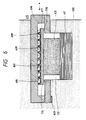
- FIGs. 5 and 6 are diagrams of details of container 415 in accordance with the present embodiment.
- Fig. 5 is a cross-sectional view showing the relationship between the positions of the probe electrode and the recording medium.
- Bimorph beams 800 are fixed on bases 801.
- Bases 801 are bonded and fixed to a frame 616 which is formed as a structure member for the information recording carrier.
- a member 700 is a recording substrate formed of the above-mentioned substrate electrode 409 for recording medium 408 and substrate 410.
- Projections 700a are formed on the recording substrate 700.
- the recording substrate 700 is fixed on a frame 617 which is connected to XY driving mechanism 413.
- the lower surfaces of bases 801 and the upper surfaces of projections 700a are finished as flat planes with high accuracy.
- the upper surfaces or projections 700a are also covered by the recording medium 408.
- the height of projections 700a is determined by high-accuracy working so that the distance between bases 801 supporting bimorph beams 800 and surface portions of recording medium 408 other than the projections (i.e., surfaces used for recording/reproduction) is set to a predetermined value.
- Recording medium on projections 700a and bases 801 slide on slide surfaces 609. This close contact between the recording medium on projections 700a and bases 801 ensures that the distance between probe electrodes 406 and the portions of recording medium 408 at which recording or reproduction is actually effected is adjusted to some degree, that is, this state is that rough adjustment of the distance has been completed.
- XY driving mechanism 413 drives recording medium 408 in X-Y directions through frame 617 while maintaining recording medium 408 on projections 700a and bases 801 in close contact. Recording medium 408 on projections 700a and bases 801 thereby slide on slide surfaces 609.
- the probe electrodes 406 and the surfaces of recording medium 408 actually used for recording or reproduction continue to maintain said state of the rough adjustment of the distance during the driving of XY driving mechanism and after the driving. There is, therefore, no need for a time-consuming operation for adjusting the distance between probe electrodes 406 and recording medium 408 each time they are moved to a large extent in X-Y directions for recording or reproduction.
- Fig. 6 shows a state in which an information recording cartridge is set in an apparatus body 630 and XY driving mechanism 413 formed of an inchworm arrangement of piezoelectric elements is inserted through window 731 by up-down mechanism 411.
- Frame 617 on which the recording substrate is fixed has a surface for connection to XY driving mechanism 413 on the opposite side from the recording medium 408.
- An electrode connector 629 is provided to supply signals and power from the control system in the main body of the apparatus to the internal circuit of the container, i.e., the information recording cartridge.
- the container is sealed by a mechanical-seal packing 770 to form a closed internal space. This closed space is defined by bases 801, frames 616 and 617, packing 770, recording substrate 700 and recording medium 408.
- Container 415 can be attached to or detached from the apparatus body 630 as indicated by the arrows.
- up-down mechanism 411 moves XY driving mechanism 413 downward to a position to avoid interference of XY driving mechanism 413 with attachment or detachment of container 415.
- each bimorph beam 800 is controlled to control the distance between each probe electrode 406 and recording medium 408 and a x-y direction fine scanning condition. Scanning of a large distance within the recording medium 408 surface is effected at a time by xy driving mechanism 413.
- the slide portion with projection is formed on the recording medium surface side, it is possible to prevent the damage caused by contact of portions of the probe electrodes, the bimorph beams and the bases with the recording/reproduction regions of the medium.
- this embodiment is directed to a unit carrying an information recording medium on which information is recorded and/or from which information is reproduced by an information recording/reproduction apparatus.
- the unit includes probes for recording information on the information recording medium and/or reproducing information from the information recording medium, a support for supporting the probes so that the probes are positioned to face the information recording medium, and slide surfaces formed on the support to enable a relative movement between the support and the information recording medium while the distance between the support and the information recording medium is maintained constant.
- this embodiment is directed to an apparatus for recording information on an information recording medium and/or reproducing information from the information recording medium.
- the apparatus includes probes for recording information on the information recording medium and/or reproducing information from the information recording medium, a support for supporting the probes so that the probes are positioned to face the information recording medium, and slide surfaces formed on the support to enable a relative movement between the support and the information recording medium while the distance between the support and the information recording medium is maintained constant. Also, the embodiment is directed to a method for recording information on an information recording medium and/or reproducing information from the information recording medium.
- the method includes the step of relatively moving the information recording medium and a support for supporting probes for information recording and/or information reproduction so that the probes are positioned to face the information recording medium, with sliding on sliding surfaces thereof while the distance between the support and the information recording medium is maintained constant, and the step of recording information on the information recording medium with the probes and/or reproducing information from the recording medium.
- the embodiment is directed to an information recording medium for information recording and/or information reproduction using probes provided in an information recording/reproduction apparatus to record information and/or reproduce information.
- the information recording medium includes recording regions in which information recording and/or information reproduction is effected with the probes, and slide surfaces which enable relative movement between the recording regions and a support for supporting the probe while the distance between the recording regions and the support is maintained constant.
- the desired distance between the medium and the probes relatively moved parallel to the surface of the medium can easily be maintained constant with high accuracy.
- a high polymer containing fluorine atoms i.e., polyimide formed by polyaddition-polymerizing pyromellitic anhydride, 2, 2-bis-(4-aminophenoxyphenyl)-1, 3-hexafluoropropane is used as a recording medium material instead of SOAZ used in the first embodiment.
- the apparatus of this embodiment is not illustrated because it is the same as that of the first embodiment. Recording, reproduction and erasing can be performed in the same manner as the first embodiment.
- polyimide containing fluorine atoms for the recording layer, the surface energy of the slide portions is reduced so that the recording substrate can be moved smoothly.
- polyimide in particular, a polyimide containing fluorine atoms is used for the recording medium and this material is also applied to the slide surface to form a slide layer for sliding on the support in accordance with this embodiment, whereby it is possible to form a suitable lubrication layer on the sliding surface simultaneously with the formation of the recording medium.
- a third embodiment of the present invention will be described below with reference to Fig. 7. Components corresponding to those of the first embodiment are indicated by the same reference numerals.
- all XY scan driving circuits 404 and all servo circuits 403 shown in Fig. 1 are incorporated in container 415 as a drive circuit 613. Except for this, the construction is the same as that of the first and second embodiments, so this embodiment is illustrated in the figure corresponding to Fig. 6.
- a selector for selection of driving of probe electrodes 406 may be included in drive circuit 613. Command signals and the like from microcomputer 401 are supplied to the drive circuit in container 415 through electrode connector 629 and electrodes 627.
- probe electrodes 406 and the recording medium are accommodated in the container and the container is detachably attached to the apparatus body.
- the recording medium can, therefore, be interchanged together with the container and there is no need to change the closed state of the interior of the container for interchange of the recording medium.
- the unit can be interchanged while maintaining probes 408 and recording medium 408 in a certain closed state. At the time of X-Y direction position control as well, this state can be maintained constant by virtue of the above-described slide portions. Therefore, probe electrodes 406 and recording medium 408 can be positioned speedily after frame insertion.
- components to be worked with accuracy including probe electrodes and recording medium 408
- they can be assembled in one unit, they can be manufactured in a process separate from the process for manufacturing rough-movement components, circuits and interface units which do not require high-precision working.
- the assembly of the apparatus is facilitated, resulting in improvement in productivity.
- the high-precision components can be interchanged by detaching the container, the apparatus can easily be maintained with respect to the damage caused by an accident.
- the probe electrodes, bimorph beams and parts are produced by micromechanics techniques and can therefore be improved in accuracy, and the drive circuit and other components can be assembled together with the bimorph beams on the same substrate.
- the recording/reproduction apparatus in accordance with the above-described embodiments may be an apparatus having the function for recording, reproduction, or 0 information recording, i.e., erasing alone, and may be an apparatus having a combination of these functions.
- an information recording medium an information recording unit, and apparatus and method for information recording and/or reproduction can be provided, wherein even during a relative movement of the probe and the recording medium parallel to the surface of the medium, the distance therebetween can be set as desired and maintained constant with high accuracy in a simple manner.
Landscapes
- Measurement Of Length, Angles, Or The Like Using Electric Or Magnetic Means (AREA)
- Length Measuring Devices With Unspecified Measuring Means (AREA)
- Management Or Editing Of Information On Record Carriers (AREA)
- Indexing, Searching, Synchronizing, And The Amount Of Synchronization Travel Of Record Carriers (AREA)
- Semiconductor Memories (AREA)
- Signal Processing For Digital Recording And Reproducing (AREA)
- Optical Recording Or Reproduction (AREA)
Applications Claiming Priority (2)
| Application Number | Priority Date | Filing Date | Title |
|---|---|---|---|
| JP280696/90 | 1990-10-19 | ||
| JP2280696A JP2744346B2 (ja) | 1990-10-19 | 1990-10-19 | 情報記録ユニットと情報記録及び/又は再生装置と情報記録及び/又は再生方法と情報記録媒体 |
Publications (3)
| Publication Number | Publication Date |
|---|---|
| EP0481498A2 EP0481498A2 (en) | 1992-04-22 |
| EP0481498A3 EP0481498A3 (en) | 1993-06-09 |
| EP0481498B1 true EP0481498B1 (en) | 1997-07-30 |
Family
ID=17628675
Family Applications (1)
| Application Number | Title | Priority Date | Filing Date |
|---|---|---|---|
| EP91117766A Expired - Lifetime EP0481498B1 (en) | 1990-10-19 | 1991-10-17 | Information recording unit and apparatus and method for information recording/reproduction |
Country Status (9)
| Country | Link |
|---|---|
| US (1) | US5392275A (es) |
| EP (1) | EP0481498B1 (es) |
| JP (1) | JP2744346B2 (es) |
| AT (1) | ATE156293T1 (es) |
| CA (1) | CA2053533C (es) |
| DE (1) | DE69127044T2 (es) |
| DK (1) | DK0481498T3 (es) |
| ES (1) | ES2103764T3 (es) |
| GR (1) | GR3024687T3 (es) |
Families Citing this family (20)
| Publication number | Priority date | Publication date | Assignee | Title |
|---|---|---|---|---|
| JP3135779B2 (ja) * | 1994-03-18 | 2001-02-19 | キヤノン株式会社 | 情報処理装置 |
| US6353219B1 (en) | 1994-07-28 | 2002-03-05 | Victor B. Kley | Object inspection and/or modification system and method |
| US6337479B1 (en) * | 1994-07-28 | 2002-01-08 | Victor B. Kley | Object inspection and/or modification system and method |
| US6339217B1 (en) * | 1995-07-28 | 2002-01-15 | General Nanotechnology Llc | Scanning probe microscope assembly and method for making spectrophotometric, near-field, and scanning probe measurements |
| US5751683A (en) * | 1995-07-24 | 1998-05-12 | General Nanotechnology, L.L.C. | Nanometer scale data storage device and associated positioning system |
| US7196328B1 (en) | 2001-03-08 | 2007-03-27 | General Nanotechnology Llc | Nanomachining method and apparatus |
| US6923044B1 (en) | 2001-03-08 | 2005-08-02 | General Nanotechnology Llc | Active cantilever for nanomachining and metrology |
| US6802646B1 (en) * | 2001-04-30 | 2004-10-12 | General Nanotechnology Llc | Low-friction moving interfaces in micromachines and nanomachines |
| US6752008B1 (en) | 2001-03-08 | 2004-06-22 | General Nanotechnology Llc | Method and apparatus for scanning in scanning probe microscopy and presenting results |
| US6787768B1 (en) | 2001-03-08 | 2004-09-07 | General Nanotechnology Llc | Method and apparatus for tool and tip design for nanomachining and measurement |
| US6411589B1 (en) * | 1998-07-29 | 2002-06-25 | Hewlett-Packard Company | System and method for forming electrostatically actuated data storage mechanisms |
| WO2001003157A1 (en) * | 1999-07-01 | 2001-01-11 | General Nanotechnology, Llc | Object inspection and/or modification system and method |
| US6931710B2 (en) | 2001-01-30 | 2005-08-23 | General Nanotechnology Llc | Manufacturing of micro-objects such as miniature diamond tool tips |
| US7253407B1 (en) | 2001-03-08 | 2007-08-07 | General Nanotechnology Llc | Active cantilever for nanomachining and metrology |
| US7053369B1 (en) * | 2001-10-19 | 2006-05-30 | Rave Llc | Scan data collection for better overall data accuracy |
| US6813937B2 (en) | 2001-11-28 | 2004-11-09 | General Nanotechnology Llc | Method and apparatus for micromachines, microstructures, nanomachines and nanostructures |
| JP2005538855A (ja) | 2002-09-09 | 2005-12-22 | ジェネラル ナノテクノロジー エルエルシー | 走査型プローブ顕微鏡の流体送達 |
| FR2869027B1 (fr) * | 2004-04-15 | 2006-07-14 | Commissariat Energie Atomique | Systeme d'enregistrement comportant une couche memoire et un reseau de micro-pointes |
| US7903532B2 (en) * | 2006-10-11 | 2011-03-08 | Seagate Technology Llc | Elevated electrodes for probe position sensing |
| US20100315938A1 (en) * | 2008-08-14 | 2010-12-16 | Nanochip, Inc. | Low distortion package for a mems device including memory |
Family Cites Families (24)
| Publication number | Priority date | Publication date | Assignee | Title |
|---|---|---|---|---|
| GB110622A (en) * | 1916-11-03 | 1917-11-01 | Frederick Samuel Yeomans | Gauze and the like Filters. |
| US2775650A (en) * | 1954-12-31 | 1956-12-25 | Bell Telephone Labor Inc | Ferroelectric recording and reproduction of speech |
| US2922986A (en) * | 1956-04-24 | 1960-01-26 | Bell Telephone Labor Inc | Ferroelectric memory device |
| GB1100622A (en) * | 1965-04-23 | 1968-01-24 | Nat Res Dev | Apparatus for reading electrostatically-stored information |
| SU631089A3 (ru) * | 1975-06-13 | 1978-12-05 | Хехст Аг, (Фирма) | Устройство дл электростатической записи |
| US4418407A (en) * | 1981-12-03 | 1983-11-29 | Rca Corporation | Video disc pickup stylus |
| US4575834A (en) * | 1982-10-05 | 1986-03-11 | Rca Corporation | Method of improving the signal-to-noise ratio in a capacitance electronic disc system |
| JPS60137168A (ja) * | 1983-12-26 | 1985-07-20 | Fujitsu Ltd | 静電記録装置 |
| US4575838A (en) * | 1984-02-29 | 1986-03-11 | Rca Corporation | Sandwich-type capacitive electronic discs |
| US4827466A (en) * | 1984-04-02 | 1989-05-02 | Victor Company Of Japan, Ltd. | Information signal recording medium electrostatic capacitance type |
| DE3610540A1 (de) * | 1986-03-27 | 1987-10-01 | Kernforschungsanlage Juelich | Bewegungseinrichtung zur mikrobewegung von objekten |
| DE3772048D1 (de) * | 1986-12-07 | 1991-09-12 | Lasarray Holding Ag | Verfahren und vorrichtung zur erzeugung von materialstrukturen im bereich atomarer dimensionen. |
| JP2556492B2 (ja) * | 1986-12-24 | 1996-11-20 | キヤノン株式会社 | 再生装置及び再生法 |
| JP2556491B2 (ja) * | 1986-12-24 | 1996-11-20 | キヤノン株式会社 | 記録装置及び記録法 |
| DE3701412A1 (de) * | 1987-01-20 | 1988-07-28 | Bayer Ag | Verfahren zum ein- bzw. auslesen von informationen in elektrisch polarisierbare schichten unter verwendung eines rastertunnelmikroskops |
| JPS63195261A (ja) * | 1987-02-09 | 1988-08-12 | Nippon Telegr & Teleph Corp <Ntt> | フツ化炭素系高分子潤滑膜の製造方法 |
| JPS643502A (en) * | 1987-06-25 | 1989-01-09 | Seiko Instr & Electronics | Scanning type tunnel microscope |
| DE3823010A1 (de) * | 1988-07-07 | 1989-09-21 | Leitz Wild Gmbh | Anordnung zum auslesen von daten |
| JP2547869B2 (ja) * | 1988-11-09 | 1996-10-23 | キヤノン株式会社 | プローブユニット,該プローブの駆動方法及び該プローブユニットを備えた走査型トンネル電流検知装置 |
| US4947042A (en) * | 1988-12-13 | 1990-08-07 | Mitsubishi Denki Kabushiki Kaisha | Tunnel unit and scanning head for scanning tunneling microscope |
| DE3918249C1 (es) * | 1989-06-05 | 1990-09-13 | Forschungszentrum Juelich Gmbh, 5170 Juelich, De | |
| US5015850A (en) * | 1989-06-20 | 1991-05-14 | The Board Of Trustees Of The Leland Stanford Junior University | Microfabricated microscope assembly |
| DE69005740T2 (de) * | 1989-08-21 | 1994-06-01 | Ngk Insulators Ltd | Aufzeichnungskopf, bestehend aus einem eine Elektrode tragenden Substrat mit einem dünnwandigen Kontaktendteil, und Schicht zur Verstärkung des Substrats. |
| US5103095A (en) * | 1990-05-23 | 1992-04-07 | Digital Instruments, Inc. | Scanning probe microscope employing adjustable tilt and unitary head |
-
1990
- 1990-10-19 JP JP2280696A patent/JP2744346B2/ja not_active Expired - Fee Related
-
1991
- 1991-10-16 CA CA002053533A patent/CA2053533C/en not_active Expired - Fee Related
- 1991-10-17 DE DE69127044T patent/DE69127044T2/de not_active Expired - Fee Related
- 1991-10-17 AT AT91117766T patent/ATE156293T1/de not_active IP Right Cessation
- 1991-10-17 DK DK91117766.5T patent/DK0481498T3/da active
- 1991-10-17 ES ES91117766T patent/ES2103764T3/es not_active Expired - Lifetime
- 1991-10-17 EP EP91117766A patent/EP0481498B1/en not_active Expired - Lifetime
-
1994
- 1994-01-03 US US08/176,516 patent/US5392275A/en not_active Expired - Fee Related
-
1997
- 1997-09-10 GR GR970402335T patent/GR3024687T3/el unknown
Also Published As
| Publication number | Publication date |
|---|---|
| JP2744346B2 (ja) | 1998-04-28 |
| DK0481498T3 (da) | 1997-09-08 |
| JPH04155635A (ja) | 1992-05-28 |
| EP0481498A2 (en) | 1992-04-22 |
| CA2053533C (en) | 1999-08-03 |
| US5392275A (en) | 1995-02-21 |
| DE69127044T2 (de) | 1998-02-12 |
| ATE156293T1 (de) | 1997-08-15 |
| CA2053533A1 (en) | 1992-04-20 |
| EP0481498A3 (en) | 1993-06-09 |
| DE69127044D1 (de) | 1997-09-04 |
| GR3024687T3 (en) | 1997-12-31 |
| ES2103764T3 (es) | 1997-10-01 |
Similar Documents
| Publication | Publication Date | Title |
|---|---|---|
| EP0481498B1 (en) | Information recording unit and apparatus and method for information recording/reproduction | |
| EP0481499B1 (en) | Memory cartridge | |
| EP0480645B1 (en) | Cantilever type probe, scanning tunnel microscope and information processing apparatus using the same | |
| US5581537A (en) | Information record/reproducing apparatus and information recording medium | |
| JP3450349B2 (ja) | カンチレバー型プローブ | |
| US5107112A (en) | Scanning tunnel-current-detecting device and method for detecting tunnel current and scanning tunnelling microscope and recording/reproducing device using thereof | |
| US5412641A (en) | Information recording/reproducing apparatus for recording/reproducing information with probes | |
| EP0492915B1 (en) | Cantilever probe and apparatus using the same | |
| US5187367A (en) | Cantilever type probe, scanning tunneling microscope and information processing device equipped with said probe | |
| CA1332761C (en) | Distance-controlled tunneling transducer and direct access storage unit employing the transducer | |
| EP0513790B1 (en) | Information processing apparatus | |
| EP0381113B1 (en) | Tunnel current data storage apparatus having separate lever bodies | |
| CA2069708C (en) | Probe-driving mechanism, production thereof, and apparatus and piezoelectric actuator employing the same | |
| US5717680A (en) | Information processing apparatus with mechanism for adjusting interval between substrate for supporting a plurality of probes and recording medium | |
| CA2051192C (en) | Tracking method for memory apparatus | |
| US5371728A (en) | Information recording/reproducing apparatus using probe | |
| EP0452851B1 (en) | Information recording/reproducing apparatus | |
| EP0537642B1 (en) | Information processing apparatus with tracking mechanism | |
| CA2118637C (en) | Information recording method and information recording apparatus | |
| US5517482A (en) | Information recording/reproducing apparatus having fuzzy operating unit | |
| CA2031733C (en) | Method for forming probe and apparatus therefor | |
| JP2946132B2 (ja) | 情報処理装置及び情報処理用カセット | |
| JPH04330653A (ja) | 情報再生装置及び情報記録再生装置 | |
| JP2934057B2 (ja) | プローブユニット及びこれを使用する情報記録及び/又は再生装置 | |
| JPH07110969A (ja) | 面合わせ方法,位置制御機構および該機構を有する情報処理装置 |
Legal Events
| Date | Code | Title | Description |
|---|---|---|---|
| PUAI | Public reference made under article 153(3) epc to a published international application that has entered the european phase |
Free format text: ORIGINAL CODE: 0009012 |
|
| AK | Designated contracting states |
Kind code of ref document: A2 Designated state(s): AT BE CH DE DK ES FR GB GR IT LI LU NL SE |
|
| PUAL | Search report despatched |
Free format text: ORIGINAL CODE: 0009013 |
|
| AK | Designated contracting states |
Kind code of ref document: A3 Designated state(s): AT BE CH DE DK ES FR GB GR IT LI LU NL SE |
|
| 17P | Request for examination filed |
Effective date: 19931105 |
|
| 17Q | First examination report despatched |
Effective date: 19951017 |
|
| GRAG | Despatch of communication of intention to grant |
Free format text: ORIGINAL CODE: EPIDOS AGRA |
|
| GRAH | Despatch of communication of intention to grant a patent |
Free format text: ORIGINAL CODE: EPIDOS IGRA |
|
| GRAH | Despatch of communication of intention to grant a patent |
Free format text: ORIGINAL CODE: EPIDOS IGRA |
|
| GRAA | (expected) grant |
Free format text: ORIGINAL CODE: 0009210 |
|
| AK | Designated contracting states |
Kind code of ref document: B1 Designated state(s): AT BE CH DE DK ES FR GB GR IT LI LU NL SE |
|
| REF | Corresponds to: |
Ref document number: 156293 Country of ref document: AT Date of ref document: 19970815 Kind code of ref document: T |
|
| REG | Reference to a national code |
Ref country code: CH Ref legal event code: EP Ref country code: CH Ref legal event code: NV Representative=s name: BOVARD AG PATENTANWAELTE |
|
| REF | Corresponds to: |
Ref document number: 69127044 Country of ref document: DE Date of ref document: 19970904 |
|
| REG | Reference to a national code |
Ref country code: DK Ref legal event code: T3 |
|
| REG | Reference to a national code |
Ref country code: ES Ref legal event code: FG2A Ref document number: 2103764 Country of ref document: ES Kind code of ref document: T3 |
|
| ET | Fr: translation filed | ||
| ITF | It: translation for a ep patent filed |
Owner name: SOCIETA' ITALIANA BREVETTI S.P.A. |
|
| REG | Reference to a national code |
Ref country code: GR Ref legal event code: FG4A Free format text: 3024687 |
|
| PLBE | No opposition filed within time limit |
Free format text: ORIGINAL CODE: 0009261 |
|
| STAA | Information on the status of an ep patent application or granted ep patent |
Free format text: STATUS: NO OPPOSITION FILED WITHIN TIME LIMIT |
|
| 26N | No opposition filed | ||
| REG | Reference to a national code |
Ref country code: GB Ref legal event code: IF02 |
|
| PGFP | Annual fee paid to national office [announced via postgrant information from national office to epo] |
Ref country code: GR Payment date: 20040924 Year of fee payment: 14 |
|
| PGFP | Annual fee paid to national office [announced via postgrant information from national office to epo] |
Ref country code: NL Payment date: 20041003 Year of fee payment: 14 |
|
| PGFP | Annual fee paid to national office [announced via postgrant information from national office to epo] |
Ref country code: SE Payment date: 20041006 Year of fee payment: 14 |
|
| PGFP | Annual fee paid to national office [announced via postgrant information from national office to epo] |
Ref country code: FR Payment date: 20041008 Year of fee payment: 14 |
|
| PGFP | Annual fee paid to national office [announced via postgrant information from national office to epo] |
Ref country code: AT Payment date: 20041013 Year of fee payment: 14 Ref country code: GB Payment date: 20041013 Year of fee payment: 14 Ref country code: LU Payment date: 20041013 Year of fee payment: 14 |
|
| PGFP | Annual fee paid to national office [announced via postgrant information from national office to epo] |
Ref country code: DK Payment date: 20041014 Year of fee payment: 14 Ref country code: DE Payment date: 20041014 Year of fee payment: 14 |
|
| PGFP | Annual fee paid to national office [announced via postgrant information from national office to epo] |
Ref country code: CH Payment date: 20041015 Year of fee payment: 14 |
|
| PGFP | Annual fee paid to national office [announced via postgrant information from national office to epo] |
Ref country code: ES Payment date: 20041116 Year of fee payment: 14 |
|
| PGFP | Annual fee paid to national office [announced via postgrant information from national office to epo] |
Ref country code: BE Payment date: 20041215 Year of fee payment: 14 |
|
| PG25 | Lapsed in a contracting state [announced via postgrant information from national office to epo] |
Ref country code: IT Free format text: LAPSE BECAUSE OF NON-PAYMENT OF DUE FEES;WARNING: LAPSES OF ITALIAN PATENTS WITH EFFECTIVE DATE BEFORE 2007 MAY HAVE OCCURRED AT ANY TIME BEFORE 2007. THE CORRECT EFFECTIVE DATE MAY BE DIFFERENT FROM THE ONE RECORDED. Effective date: 20051017 Ref country code: GB Free format text: LAPSE BECAUSE OF NON-PAYMENT OF DUE FEES Effective date: 20051017 Ref country code: AT Free format text: LAPSE BECAUSE OF NON-PAYMENT OF DUE FEES Effective date: 20051017 |
|
| PG25 | Lapsed in a contracting state [announced via postgrant information from national office to epo] |
Ref country code: ES Free format text: LAPSE BECAUSE OF NON-PAYMENT OF DUE FEES Effective date: 20051018 Ref country code: SE Free format text: LAPSE BECAUSE OF NON-PAYMENT OF DUE FEES Effective date: 20051018 |
|
| PG25 | Lapsed in a contracting state [announced via postgrant information from national office to epo] |
Ref country code: LU Free format text: LAPSE BECAUSE OF NON-PAYMENT OF DUE FEES Effective date: 20051031 Ref country code: LI Free format text: LAPSE BECAUSE OF NON-PAYMENT OF DUE FEES Effective date: 20051031 Ref country code: CH Free format text: LAPSE BECAUSE OF NON-PAYMENT OF DUE FEES Effective date: 20051031 Ref country code: DK Free format text: LAPSE BECAUSE OF NON-PAYMENT OF DUE FEES Effective date: 20051031 Ref country code: BE Free format text: LAPSE BECAUSE OF NON-PAYMENT OF DUE FEES Effective date: 20051031 |
|
| PG25 | Lapsed in a contracting state [announced via postgrant information from national office to epo] |
Ref country code: NL Free format text: LAPSE BECAUSE OF NON-PAYMENT OF DUE FEES Effective date: 20060501 |
|
| PG25 | Lapsed in a contracting state [announced via postgrant information from national office to epo] |
Ref country code: DE Free format text: LAPSE BECAUSE OF NON-PAYMENT OF DUE FEES Effective date: 20060503 |
|
| REG | Reference to a national code |
Ref country code: DK Ref legal event code: EBP |
|
| REG | Reference to a national code |
Ref country code: CH Ref legal event code: PL |
|
| EUG | Se: european patent has lapsed | ||
| GBPC | Gb: european patent ceased through non-payment of renewal fee |
Effective date: 20051017 |
|
| PG25 | Lapsed in a contracting state [announced via postgrant information from national office to epo] |
Ref country code: FR Free format text: LAPSE BECAUSE OF NON-PAYMENT OF DUE FEES Effective date: 20060630 |
|
| NLV4 | Nl: lapsed or anulled due to non-payment of the annual fee |
Effective date: 20060501 |
|
| REG | Reference to a national code |
Ref country code: FR Ref legal event code: ST Effective date: 20060630 |
|
| REG | Reference to a national code |
Ref country code: ES Ref legal event code: FD2A Effective date: 20051018 |
|
| BERE | Be: lapsed |
Owner name: *CANON K.K. Effective date: 20051031 |
|
| PG25 | Lapsed in a contracting state [announced via postgrant information from national office to epo] |
Ref country code: GR Free format text: LAPSE BECAUSE OF NON-PAYMENT OF DUE FEES Effective date: 19970730 |