EP0480828B1 - Dispositif d'apport de poudre pour revêtements par traitement au faisceau laser - Google Patents
Dispositif d'apport de poudre pour revêtements par traitement au faisceau laser Download PDFInfo
- Publication number
- EP0480828B1 EP0480828B1 EP91402693A EP91402693A EP0480828B1 EP 0480828 B1 EP0480828 B1 EP 0480828B1 EP 91402693 A EP91402693 A EP 91402693A EP 91402693 A EP91402693 A EP 91402693A EP 0480828 B1 EP0480828 B1 EP 0480828B1
- Authority
- EP
- European Patent Office
- Prior art keywords
- powder
- diffuser
- supply device
- chamber
- delivery pipe
- Prior art date
- Legal status (The legal status is an assumption and is not a legal conclusion. Google has not performed a legal analysis and makes no representation as to the accuracy of the status listed.)
- Expired - Lifetime
Links
Images
Classifications
-
- B—PERFORMING OPERATIONS; TRANSPORTING
- B05—SPRAYING OR ATOMISING IN GENERAL; APPLYING FLUENT MATERIALS TO SURFACES, IN GENERAL
- B05B—SPRAYING APPARATUS; ATOMISING APPARATUS; NOZZLES
- B05B7/00—Spraying apparatus for discharge of liquids or other fluent materials from two or more sources, e.g. of liquid and air, of powder and gas
- B05B7/14—Spraying apparatus for discharge of liquids or other fluent materials from two or more sources, e.g. of liquid and air, of powder and gas designed for spraying particulate materials
- B05B7/1404—Arrangements for supplying particulate material
-
- B—PERFORMING OPERATIONS; TRANSPORTING
- B05—SPRAYING OR ATOMISING IN GENERAL; APPLYING FLUENT MATERIALS TO SURFACES, IN GENERAL
- B05B—SPRAYING APPARATUS; ATOMISING APPARATUS; NOZZLES
- B05B7/00—Spraying apparatus for discharge of liquids or other fluent materials from two or more sources, e.g. of liquid and air, of powder and gas
- B05B7/16—Spraying apparatus for discharge of liquids or other fluent materials from two or more sources, e.g. of liquid and air, of powder and gas incorporating means for heating or cooling the material to be sprayed
- B05B7/22—Spraying apparatus for discharge of liquids or other fluent materials from two or more sources, e.g. of liquid and air, of powder and gas incorporating means for heating or cooling the material to be sprayed electrically, magnetically or electromagnetically, e.g. by arc
- B05B7/228—Spraying apparatus for discharge of liquids or other fluent materials from two or more sources, e.g. of liquid and air, of powder and gas incorporating means for heating or cooling the material to be sprayed electrically, magnetically or electromagnetically, e.g. by arc using electromagnetic radiation, e.g. laser
-
- B—PERFORMING OPERATIONS; TRANSPORTING
- B23—MACHINE TOOLS; METAL-WORKING NOT OTHERWISE PROVIDED FOR
- B23K—SOLDERING OR UNSOLDERING; WELDING; CLADDING OR PLATING BY SOLDERING OR WELDING; CUTTING BY APPLYING HEAT LOCALLY, e.g. FLAME CUTTING; WORKING BY LASER BEAM
- B23K26/00—Working by laser beam, e.g. welding, cutting or boring
- B23K26/14—Working by laser beam, e.g. welding, cutting or boring using a fluid stream, e.g. a jet of gas, in conjunction with the laser beam; Nozzles therefor
- B23K26/1462—Nozzles; Features related to nozzles
-
- B—PERFORMING OPERATIONS; TRANSPORTING
- B23—MACHINE TOOLS; METAL-WORKING NOT OTHERWISE PROVIDED FOR
- B23K—SOLDERING OR UNSOLDERING; WELDING; CLADDING OR PLATING BY SOLDERING OR WELDING; CUTTING BY APPLYING HEAT LOCALLY, e.g. FLAME CUTTING; WORKING BY LASER BEAM
- B23K26/00—Working by laser beam, e.g. welding, cutting or boring
- B23K26/34—Laser welding for purposes other than joining
-
- B—PERFORMING OPERATIONS; TRANSPORTING
- B23—MACHINE TOOLS; METAL-WORKING NOT OTHERWISE PROVIDED FOR
- B23K—SOLDERING OR UNSOLDERING; WELDING; CLADDING OR PLATING BY SOLDERING OR WELDING; CUTTING BY APPLYING HEAT LOCALLY, e.g. FLAME CUTTING; WORKING BY LASER BEAM
- B23K9/00—Arc welding or cutting
- B23K9/32—Accessories
- B23K9/324—Devices for supplying or evacuating a shielding or a welding powder, e.g. a magnetic powder
-
- C—CHEMISTRY; METALLURGY
- C23—COATING METALLIC MATERIAL; COATING MATERIAL WITH METALLIC MATERIAL; CHEMICAL SURFACE TREATMENT; DIFFUSION TREATMENT OF METALLIC MATERIAL; COATING BY VACUUM EVAPORATION, BY SPUTTERING, BY ION IMPLANTATION OR BY CHEMICAL VAPOUR DEPOSITION, IN GENERAL; INHIBITING CORROSION OF METALLIC MATERIAL OR INCRUSTATION IN GENERAL
- C23C—COATING METALLIC MATERIAL; COATING MATERIAL WITH METALLIC MATERIAL; SURFACE TREATMENT OF METALLIC MATERIAL BY DIFFUSION INTO THE SURFACE, BY CHEMICAL CONVERSION OR SUBSTITUTION; COATING BY VACUUM EVAPORATION, BY SPUTTERING, BY ION IMPLANTATION OR BY CHEMICAL VAPOUR DEPOSITION, IN GENERAL
- C23C24/00—Coating starting from inorganic powder
- C23C24/08—Coating starting from inorganic powder by application of heat or pressure and heat
- C23C24/10—Coating starting from inorganic powder by application of heat or pressure and heat with intermediate formation of a liquid phase in the layer
Definitions
- the invention relates to a powder supply device intended for producing coatings by LASER beam treatment.
- US-A-4 270 675 describes a powder distributor in which the regularity of the flow is ensured by a rod connected to a vibrator.
- FR-A-2 452 528 provides for a regulating device regulating the admission of the powder particles into a tube traversed by the carrier gas.
- US-A-4,730,093, US-A-4,743,733 and FR-A-2,642,690 describe a device comprising a volumetric wheel attached to the reservoir and a powder supply pipe equipped with an air vibrator.
- EP-A-0 173 654 provides for control of the powder supply parameters.
- EP-A-0 335 503 discloses a device for cleaning or cutting by pressurized liquid jet entraining abrasive particles, comprising provisions for adjusting the flow rate.
- the object of the invention is therefore to obtain a device which makes it possible to bring the powder to a chosen location with respect to the LASER energy beam, in a localized manner and with a low particle speed, thus avoiding the drawbacks noted above. above and in particular an insufficient yield due to the loss of powder as well as the risks of disturbances by blowing which would be detrimental to the quality of the results.
- a powder supply device and meeting these conditions is characterized in that on the powder supply pipe is inserted a pressure reduction chamber into which penetrates the upstream part of said powder supply pipe, the end of said upstream part carrying a powder diffuser in the expansion chamber, said chamber comprising at least one conical part integral with the downstream part of the powder supply conduit terminated by a nozzle and further comprising a conduit exhaust fitted with a flow control and placed on a face opposite to said downstream part of the powder supply duct.
- the position of said powder diffuser is adjustable in height inside the expansion chamber and, moreover, the outlet nozzle may include a diffusion diffuser. protective gas and / or water cooling device.
- a powder supply installation for LASER deposition schematically represented in FIG. 1 comprises, as is generally known for various applications known per se, a generator 1 of a LASER type energy beam, an optical system 2 for focusing the bundle, a powder distributor 3 of a type known per se comprising its control device and in particular a flow meter as well as a powder reserve and a connection to a source of supply of carrier gas of the neutral gas type such as, by example, argon.
- the powder is brought into a melting zone resulting from the LASER beam by a conduit 4 comprising in particular certain flexible parts 5 and certain rigid parts 6.
- a chamber 7 having at least one section 5 enlarged relative to the section s of the inlet conduit 8, part of which penetrates to the inside said chamber 7.
- the end of said inlet duct 8 carries a powder diffuser 9 whose position inside the chamber 7 is adjustable, in particular in height.
- the diffuser 9 comprises in particular passages 9a for distributing the powder.
- the chamber 7 provides a relaxation of the carrier gas while the diffuser 9 ensures a regular and calibrated flow of the powder.
- the inner surface of the chamber 7 is polished and free of any roughness in order to avoid retaining powder.
- Chamber 7 has at least one conical part 10 at its base to which an outlet duct 11 is connected.
- the flow rate in this outlet duct 11 is less than the flow rate in the inlet duct 8 is adjusted at the level of the expansion chamber 7 by means of a flow adjustment effected by means of a valve 12 arranged, an exhaust duct 13 placed on the chamber 7 and connected to the face 14 of the said chamber 7, opposite the outlet. Said outlet conduit 11 is terminated by an ejection nozzle 15.
- the operation of the device can easily be deduced from the description which has just been made with reference to FIGS. 1 and 2.
- the quantity of powder necessary for the laser treatment to be implemented is adjusted, as well as the pressure and flow ensuring a delivery of the powder with carrier gas to the chamber 7 without risk of accumulation by creation of plug and smoothly.
- the diffuser 9 is interchangeable.
- the speed of the powder at the outlet of the chamber 7 being adjusted by means of the exhaust valve 12, the powder is brought at low speed, through the nozzle 15 to the treatment zone to the LASER beam of a part 16
- the powder is brought in, uniformly and in a concentrated manner on the focal task of the LASER beam.
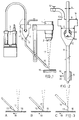
- FIG. 3 shows diagrammatically in FIG. 3, depending on the particular applications envisaged, different working configurations are possible.
- the ejection nozzle 15 is also provided interchangeable and its outlet diameter which can be less than 1 mm is determined according to the particular applications and is adapted to the size of the focal spot so as to obtain the fusion of the maximum amount of powder brought into the beam. In some cases, and in particular to increase the life of the nozzle 15 by avoiding rapid deterioration due to excessive heating, it may be advantageous to add to said nozzle 15 water cooling.
- the ejection nozzle 15 is advantageously equipped with an integrated gas diffuser 19.
- the nozzle 15 is wrapped in a double jacket constituting the diffuser 19, the space thus provided being supplied by at least one pipe 20 in protective neutral gas.
- the additional gas flow has the effect of ensuring protection against oxidation of the deposited material and of the treated area of the part 16.
Description
- L'invention concerne un dispositif d'apport de poudre destiné à la réalisation de revêtements par traitement au faisceau LASER.
- Des techniques de réalisation de revêtements à partir d'apport de poudre faisant intervenir une fusion au moyen d'un faisceau énergétique, notamment de type LASER, ont été largement développées. Des exemples de mise en oeuvre sont donnés par FR-A-2 605 310, EP-A-0 212 938, EP-A-0 213 498 et GB-A-2 184 380.
- Les équipements utilisés comportent généralement un dispositif d'apport de poudre dont le principe est similaire à celui des distributeurs de poudre antérieurement connus et utilisés dans la réalisation de revêtements par projection à la flamme plasma et qui fonctionnent notamment en ayant comme véhicule un gaz porteur sous des pression et débit déterminés, généralement un gaz neutre tel que l'argon. Ces techniques dans leur application aux dépôts sous faisceau LASER ont cependant soulevé des problèmes :
- la vitesse élevée des particules de poudre entraînées par le gaz porteur entraîne des pertes et un gaspillage de la poudre,
- les intersections du faisceau LASER et de la matière sont perturbées par des phénomènes de soufflage.
- Certaines tentatives de solutions et d'améliorations aux dispositifs précédents ont été proposés. C'est ainsi que US-A-4 270 675 décrit un distributeur de poudre dans lequel la régularité du débit est assurée par une tige reliée à un vibrateur. FR-A-2 452 528 prévoit un dispositif régulateur réglant l'admission des particules de poudre dans un tube parcouru par le gaz porteur. US-A-4 730 093, US-A-4 743 733 et FR-A-2 642 690 décrivent un dispositif comportant une roue volumétrique adjointe au réservoir et un conduit d'amenée de poudre équipé d'un vibrateur à air. EP-A-0 173 654 prévoit un asservissement des paramètres d'apport de poudre. On connaît par EP-A-0 335 503 un appareil de nettoyage ou découpe par jet liquide sous pression entraînant des particules abrasives, comportant des dispositions de réglage du débit.
- Toutefois, aucune de ces solutions connues ne donne entière satisfaction et dans certaines applications particulières les problèmes relevés ci-dessus ne sont pas complètement résolus par l'utilisation des équipements connus. Le but de l'invention est par conséquent d'obtenir un dispositif qui permet d'amener la poudre à un endroit choisi par rapport au faisceau énergétique LASER, de façon localisée et avec une faible vitesse de particule, évitant ainsi les inconvénients relevés ci-dessus et notamment un rendement insuffisant dû aux pertes de poudre ainsi que les risques de perturbations par soufflage qui seraient nuisibles à la qualité des résultats.
- Un dispositif d'apport de poudre conforme à l'invention et répondant à ces conditions est caractérisé en ce que sur le conduit d'amenée de poudre est insérée une chambre de détente dans laquelle pénètre la partie amont dudit conduit d'amenée de poudre, l'extrémité de ladite partie amont portant un diffuseur de poudre dans la chambre de détente, ladite chambre comportant au moins une partie conique solidaire de la partie aval du conduit d'amenée de poudre terminée par une buse et comportant en outre, un conduit d'échappement muni d'un réglage de débit et placé sur une face opposée à ladite partie aval du conduit d'amenée de poudre.
- Avantageusement, la position dudit diffuseur de poudre est réglable en hauteur à l'intérieur de la chambre de détente et, par ailleurs, la buse de sortie peut comporter un diffuseur de gaz protecteur et/ou un dispositif de refroidissement par eau.
- D'autres caractéristiques et avantages de l'invention seront mieux compris à la lecture de la description qui va suivre d'un mode de réalisation de l'invention, en référence aux dessins annexés sur lesquels ;
- la figure 1 représente une vue schématique d'ensemble d'une installation d'apport de poudre pour dépôt au LASER ;
- la figure 2 montre, selon un détail agrandi de la figure 1, une vue schématique en coupe d'une chambre de détente à diffuseur de poudre constituant le dispositif d'apport de poudre conforme à l'invention ;
- la figure 3 montre schématiquement les variantes A, B, C de position de la buse du dispositif d'apport de poudre représenté sur les figures 1 et 2.
- Une installation d'apport de poudre pour dépôt au LASER schématiquement représentée sur la figure 1 comporte, comme cela est généralement connu pour diverses applications connues en soi, un générateur 1 d'un faisceau énergétique de type LASER, un système optique 2 de focalisation du faisceau, un distributeur de poudre 3 d'un type connu en soi comportant son dispositif de commande et notamment un débitmètre ainsi qu'une réserve de poudre et une liaison à une source d'alimentation en gaz porteur du type gaz neutre tel que, par exemple, de l'argon. De manière habituelle et généralement connue, la poudre est amenée dans une zone de fusion résultant du faisceau LASER par un conduit 4 comportant notamment certaines parties souples 5 et certaines parties rigides 6.
- De manière remarquable et conforme à l'invention, tel que représenté plus en détails sur la figure 2, sur ledit conduit 4 d'amenée de poudre, est insérée une chambre 7 présentant au moins une section 5 élargie par rapport à la section s du conduit d'arrivée 8 dont une partie pénètre à l'intérieur de ladite chambre 7. L'extrémité dudit conduit d'arrivée 8 porte un diffuseur 9 de poudre dont la position à l'intérieur de la chambre 7 est réglable, notamment en hauteur. Le diffuseur 9 comporte notamment des passages 9a de répartition de la poudre. La chambre 7 procure une détente du gaz porteur tandis que le diffuseur 9 assure un écoulement régulier et calibré de la poudre. La surface intérieure de la chambre 7 est polie et exempte de toute aspérité afin d'éviter les retenues de poudre. La chambre 7 comporte au moins une partie conique 10 à sa base à laquelle est raccordé un conduit de sortie 11. Le débit dans ce conduit de sortie 11 inférieur au débit dans le conduit d'arrivée 8 est ajusté au niveau de la chambre de détente 7 au moyen d'un réglage de débit effectué grâce à une vanne 12 disposée, un conduit d'échappement 13 placé sur la chambre 7 et raccordé sur la face 14 de ladite chambre 7, opposée à la sortie. Ledit conduit de sortie 11 est terminé par une buse 15 d'éjection.
- Le fonctionnement du dispositif se déduit aisément de la description qui vient d'en être faite en référence aux figures 1 et 2. Au niveau du distributeur de poudre 3 sont réglés la quantité de poudre nécessaire pour le traitement au laser à mettre en oeuvre ainsi que les pression et débit assurant un acheminement de la poudre avec gaz porteur jusqu'à la chambre 7 sans risque d'accumulation par création de bouchon et sans à-coups.
- Un écoulement correct de la poudre à l'intérieur de la chambre 7 elle-même est ensuite assuré au moyen du diffuseur 9. En fonction des applications particulières, cet élément du dispositif, le diffuseur 9 est interchangeable. La vitesse de la poudre à la sortie de la chambre 7 étant réglée au moyen de la vanne d'échappement 12, la poudre est amenée à faible vitesse, à travers la buse 15 sur la zone de traitement au faisceau LASER d'une pièce 16. En fait, de cette manière, la poudre est amenée, uniformément et de façon concentrée sur la tâche focale du faisceau LASER.
Comme représenté schématiquement sur la figure 3, suivant les applications particulières envisagées, différentes configurations de travail sont possibles. Suivant la position adoptée pour la buse d'éjection 15 par rapport au faisceau LASER symbolisé en 17, on peut ainsi obtenir, selon la variante A, une pré-déposition de la poudre en amont du faisceau LASER ou selon la variante B, une injection de la poudre dans le bain de fusion créé par l'irradiation du faisceau LASER sur la pièce 16 ou encore, selon la variante C, une injection de la poudre directement dans le faisceau. Le sens de déplacement étant représenté par les flèches 18, la buse 15 a été représentée en position amont sur la figure 3 et des configurations similaires peuvent être prévues en plaçant ladite buse 15 en position aval par rapport au faisceau LASER. - La buse 15 d'éjection est également prévue interchangeable et son diamètre de sortie qui peut être inférieur à 1 mm est déterminé en fonction des applications particulières et est adaptée à la dimension de la tache focale de manière à obtenir la fusion de la quantité maximale de poudre amenée dans le faisceau. Dans certains cas, et notamment pour accroître la durée de vie de la buse 15 en évitant une détérioration rapide dûe à un échauffement excessif, il peut être avantageux d'adjoindre à ladite buse 15 un refroidissement par eau.
- Dans certains cas également, la buse 15 d'éjection est avantageusement équipée d'un diffuseur 19 de gaz intégré.
- Dans ce cas, la buse 15 est enveloppée d'une double chemise constituant le diffuseur 19, l'espace ainsi ménagé étant alimenté par au moins une canalisation 20 en gaz neutre protecteur.
- Le flux gazeux complémentaire a pour effet d'assurer une protection contre l'oxydation du matériau déposé et de la zone traitée de la pièce 16.
- Il permet également, par soufflage, de débarrasser ladite zone traitée d'éventuels excès de poudre non fondus et d'obtenir ainsi une surface saine, sans que l'amenée du flux de poudre soit perturbée en cours d'opération.
Claims (3)
- Dispositif d'apport de poudre destiné à la réalisation de revêtements par traitement au faisceau LASER, ledit dispositif comportant un appareil distributeur (3) de poudre fournissant de la poudre avec gaz porteur dans un conduit d'amenée de poudre (4) vers une surface à revêtir caractérisé en ce que sur ledit conduit d'amenée de poudre (4) est insérée une chambre (7) de détente dans laquelle pénètre la partie amont dudit conduit d'amenée de poudre, l'extrémité (8) de ladite partie amont portant un diffuseur (9) de poudre dans la chambre de détente, ladite chambre (7) comportant au moins une partie conique (10) solidaire de la partie aval (11) du conduit d'amenée de poudre terminée par une buse (15) et, comportant en outre, un conduit d'échappement (13) muni d'un réglage de débit (12) et placé sur une face (14) opposée à ladite partie aval (11) du conduit d'amenée de poudre.
- Dispositif d'apport de poudre selon la revendication 1 dans lequel la position dudit diffuseur (9) de poudre est réglable en hauteur à l'intérieur de ladite chambre (7) de détente et ledit diffuseur (9) comporte des passages (9a) de répartition de poudre.
- Dispositif d'apport de poudre selon l'une des revendications 1 ou 2 dans lequel ladite buse (15) de sortie amenant le flux de poudre est entourée d'une double chemise reliée à une source d'alimentation en gaz protecteur, formant un diffuseur (19) de gaz.
Applications Claiming Priority (2)
| Application Number | Priority Date | Filing Date | Title |
|---|---|---|---|
| FR9012479 | 1990-10-10 | ||
| FR9012479A FR2667811B1 (fr) | 1990-10-10 | 1990-10-10 | Dispositif d'apport de poudre pour revetement par traitement au faisceau laser. |
Publications (2)
| Publication Number | Publication Date |
|---|---|
| EP0480828A1 EP0480828A1 (fr) | 1992-04-15 |
| EP0480828B1 true EP0480828B1 (fr) | 1994-07-13 |
Family
ID=9401087
Family Applications (1)
| Application Number | Title | Priority Date | Filing Date |
|---|---|---|---|
| EP91402693A Expired - Lifetime EP0480828B1 (fr) | 1990-10-10 | 1991-10-09 | Dispositif d'apport de poudre pour revêtements par traitement au faisceau laser |
Country Status (5)
| Country | Link |
|---|---|
| US (1) | US5182430A (fr) |
| EP (1) | EP0480828B1 (fr) |
| JP (1) | JP2680493B2 (fr) |
| DE (1) | DE69102852T2 (fr) |
| FR (1) | FR2667811B1 (fr) |
Families Citing this family (53)
| Publication number | Priority date | Publication date | Assignee | Title |
|---|---|---|---|---|
| ATE117027T1 (de) * | 1991-02-02 | 1995-01-15 | Theysohn Friedrich Fa | Verfahren zur erzeugung einer verschleissmindernden schicht. |
| DE4224886C2 (de) * | 1992-07-28 | 1994-08-04 | Deutsche Forsch Luft Raumfahrt | Oberflächenbeschichtungsvorrichtung |
| DE4322801C1 (de) * | 1993-07-08 | 1994-10-13 | Wagner Int | Verfahren zum Pulverbeschichten von Werkstücken |
| US5725670A (en) | 1994-02-18 | 1998-03-10 | Nordson Corporation | Apparatus for powder coating welded cans |
| US5486676A (en) * | 1994-11-14 | 1996-01-23 | General Electric Company | Coaxial single point powder feed nozzle |
| US5814152A (en) * | 1995-05-23 | 1998-09-29 | Mcdonnell Douglas Corporation | Apparatus for coating a substrate |
| US5837960A (en) * | 1995-08-14 | 1998-11-17 | The Regents Of The University Of California | Laser production of articles from powders |
| US5961862A (en) * | 1995-11-30 | 1999-10-05 | The Regents Of The University Of California | Deposition head for laser |
| US6046426A (en) * | 1996-07-08 | 2000-04-04 | Sandia Corporation | Method and system for producing complex-shape objects |
| US6429402B1 (en) | 1997-01-24 | 2002-08-06 | The Regents Of The University Of California | Controlled laser production of elongated articles from particulates |
| US7045015B2 (en) | 1998-09-30 | 2006-05-16 | Optomec Design Company | Apparatuses and method for maskless mesoscale material deposition |
| US7938079B2 (en) * | 1998-09-30 | 2011-05-10 | Optomec Design Company | Annular aerosol jet deposition using an extended nozzle |
| US6251488B1 (en) * | 1999-05-05 | 2001-06-26 | Optomec Design Company | Precision spray processes for direct write electronic components |
| US7108894B2 (en) * | 1998-09-30 | 2006-09-19 | Optomec Design Company | Direct Write™ System |
| US20030020768A1 (en) * | 1998-09-30 | 2003-01-30 | Renn Michael J. | Direct write TM system |
| US7294366B2 (en) * | 1998-09-30 | 2007-11-13 | Optomec Design Company | Laser processing for heat-sensitive mesoscale deposition |
| US8110247B2 (en) * | 1998-09-30 | 2012-02-07 | Optomec Design Company | Laser processing for heat-sensitive mesoscale deposition of oxygen-sensitive materials |
| US20040197493A1 (en) * | 1998-09-30 | 2004-10-07 | Optomec Design Company | Apparatus, methods and precision spray processes for direct write and maskless mesoscale material deposition |
| DE19915038A1 (de) * | 1999-04-01 | 2000-10-26 | Vaw Ver Aluminium Werke Ag | Leichtmetallzylinderblock, Verfahren zu seiner Herstellung und Vorrichtung zur Durchführung des Verfahrens |
| US6305884B1 (en) * | 1999-04-29 | 2001-10-23 | The Regents Of The University Of California | Rotary powder feed through apparatus |
| US6263918B1 (en) | 1999-04-29 | 2001-07-24 | The Regents Of The University Of California | Multiple feed powder splitter |
| US6294225B1 (en) * | 1999-05-10 | 2001-09-25 | The University Of Tennessee Research Corporation | Method for improving the wear and corrosion resistance of material transport trailer surfaces |
| US6331693B1 (en) | 1999-06-28 | 2001-12-18 | Cincinnati Incorporated | Beam delivery system |
| US6396025B1 (en) | 1999-07-01 | 2002-05-28 | Aeromet Corporation | Powder feed nozzle for laser welding |
| ATE312680T1 (de) * | 2000-06-13 | 2005-12-15 | Element Six Pty Ltd | Verbunddiamantkörper |
| US7045738B1 (en) * | 2002-10-01 | 2006-05-16 | Southern Methodist University | Powder delivery system and method |
| US6995334B1 (en) | 2003-08-25 | 2006-02-07 | Southern Methodist University | System and method for controlling the size of the molten pool in laser-based additive manufacturing |
| US7666522B2 (en) * | 2003-12-03 | 2010-02-23 | IMDS, Inc. | Laser based metal deposition (LBMD) of implant structures |
| US7001672B2 (en) | 2003-12-03 | 2006-02-21 | Medicine Lodge, Inc. | Laser based metal deposition of implant structures |
| US20050212694A1 (en) * | 2004-03-26 | 2005-09-29 | Chun-Ta Chen | Data distribution method and system |
| US7674671B2 (en) | 2004-12-13 | 2010-03-09 | Optomec Design Company | Aerodynamic jetting of aerosolized fluids for fabrication of passive structures |
| US7938341B2 (en) * | 2004-12-13 | 2011-05-10 | Optomec Design Company | Miniature aerosol jet and aerosol jet array |
| US20080013299A1 (en) * | 2004-12-13 | 2008-01-17 | Optomec, Inc. | Direct Patterning for EMI Shielding and Interconnects Using Miniature Aerosol Jet and Aerosol Jet Array |
| FI119923B (fi) * | 2005-09-08 | 2009-05-15 | Kemppi Oy | Menetelmä ja laitteisto lyhytkaarihitsausta varten |
| US20070154634A1 (en) * | 2005-12-15 | 2007-07-05 | Optomec Design Company | Method and Apparatus for Low-Temperature Plasma Sintering |
| US7951412B2 (en) * | 2006-06-07 | 2011-05-31 | Medicinelodge Inc. | Laser based metal deposition (LBMD) of antimicrobials to implant surfaces |
| TWI341872B (en) * | 2006-08-07 | 2011-05-11 | Ind Tech Res Inst | Plasma deposition apparatus and depositing method thereof |
| US20100310630A1 (en) * | 2007-04-27 | 2010-12-09 | Technische Universitat Braunschweig | Coated surface for cell culture |
| TWI482662B (zh) * | 2007-08-30 | 2015-05-01 | Optomec Inc | 機械上一體式及緊密式耦合之列印頭以及噴霧源 |
| TW200918325A (en) * | 2007-08-31 | 2009-05-01 | Optomec Inc | AEROSOL JET® printing system for photovoltaic applications |
| TWI538737B (zh) * | 2007-08-31 | 2016-06-21 | 阿普托麥克股份有限公司 | 材料沉積總成 |
| US8887658B2 (en) * | 2007-10-09 | 2014-11-18 | Optomec, Inc. | Multiple sheath multiple capillary aerosol jet |
| US8704120B2 (en) * | 2008-07-03 | 2014-04-22 | Esab Ab | Device for handling powder for a welding apparatus |
| US8297478B2 (en) * | 2008-09-30 | 2012-10-30 | Honeywell International Inc. | Powder feed cylinder assemblies and powder feeders |
| US9168613B2 (en) | 2010-10-22 | 2015-10-27 | Paul T. Colby | Vertical laser cladding system |
| JP5929935B2 (ja) * | 2014-01-17 | 2016-06-08 | トヨタ自動車株式会社 | レーザクラッド加工における品質管理方法及びレーザクラッド加工装置 |
| CN104384066A (zh) * | 2014-10-30 | 2015-03-04 | 昆山迈致治具科技有限公司 | 一种点胶治具 |
| DE102014116275A1 (de) * | 2014-11-07 | 2016-05-12 | Webasto SE | Verfahren zur Herstellung eines Kontaktbereichs für eine Schicht eines elektrischen Heizgeräts sowie Vorrichtung für ein elektrisches Heizgerät für ein Kraftfahrzeug |
| EP3256308B1 (fr) | 2015-02-10 | 2022-12-21 | Optomec, Inc. | Fabrication de structures tridimensionnelles par durcissement en vol d'aérosols |
| US10688596B2 (en) * | 2015-12-18 | 2020-06-23 | Illinois Tool Works Inc. | Wire manufactured by additive manufacturing methods |
| KR20200087196A (ko) | 2017-11-13 | 2020-07-20 | 옵토멕 인코포레이티드 | 에어로졸 스트림의 셔터링 |
| DE102018113643A1 (de) * | 2018-06-07 | 2019-12-12 | Durum Verschleißschutz GmbH | Vorrichtung zur Beschichtung einer Oberfläche |
| PL3789512T3 (pl) * | 2019-09-09 | 2024-04-02 | Sturm Maschinen- & Anlagenbau Gmbh | Instalacja i sposób powlekania tarcz hamulcowych lub bębnów hamulcowych |
Family Cites Families (14)
| Publication number | Priority date | Publication date | Assignee | Title |
|---|---|---|---|---|
| US4200669A (en) * | 1978-11-22 | 1980-04-29 | The United States Of America As Represented By The Secretary Of The Navy | Laser spraying |
| GB2052566B (en) * | 1979-03-30 | 1982-12-15 | Rolls Royce | Laser aplication of hard surface alloy |
| US4270675A (en) * | 1979-10-29 | 1981-06-02 | United Technologies Corporation | Powder feed apparatus |
| IT1179061B (it) * | 1984-08-20 | 1987-09-16 | Fiat Auto Spa | Procedimento per l'effettuazione di un trattamento su pezzi metallici con l'aggiunta di un materiale d'apporto e con l'impiego di un laser di potenza |
| US4743733A (en) * | 1984-10-01 | 1988-05-10 | General Electric Company | Method and apparatus for repairing metal in an article |
| US4730093A (en) * | 1984-10-01 | 1988-03-08 | General Electric Company | Method and apparatus for repairing metal in an article |
| US4746540A (en) * | 1985-08-13 | 1988-05-24 | Toyota Jidosha Kabushiki Kaisha | Method for forming alloy layer upon aluminum alloy substrate by irradiating with a CO2 laser, on substrate surface, alloy powder containing substance for alloying and silicon or bismuth |
| EP0213498A3 (fr) * | 1985-08-13 | 1989-07-12 | Toyota Jidosha Kabushiki Kaisha | Procédé de formation d'une couche d'alliage sur un substrat en alliage d'aluminium par application d'une poudre contenant un matériau d'alliage et du titane ou du manganèse et irradiation par laser à CO2 |
| JPS62118990A (ja) * | 1985-11-18 | 1987-05-30 | Daido Metal Kogyo Kk | 摺動部材用複合材料の製造方法 |
| FR2605310B1 (fr) * | 1986-10-16 | 1992-04-30 | Comp Generale Electricite | Procede de renforcement de pieces ceramiques par traitement au laser |
| EP0408609A1 (fr) * | 1988-03-02 | 1991-01-23 | Cleaning Technology Limited | Nettoyage ou decoupage par abrasion |
| US4835357A (en) * | 1988-06-20 | 1989-05-30 | Williams International Corporation | Sheet metal laser welding |
| IL92428A (en) * | 1989-02-08 | 1992-12-01 | Gen Electric | Fabrication of components by layered deposition |
| US5038014A (en) * | 1989-02-08 | 1991-08-06 | General Electric Company | Fabrication of components by layered deposition |
-
1990
- 1990-10-10 FR FR9012479A patent/FR2667811B1/fr not_active Expired - Lifetime
-
1991
- 1991-10-07 JP JP3259309A patent/JP2680493B2/ja not_active Expired - Fee Related
- 1991-10-09 DE DE69102852T patent/DE69102852T2/de not_active Expired - Lifetime
- 1991-10-09 EP EP91402693A patent/EP0480828B1/fr not_active Expired - Lifetime
- 1991-10-10 US US07/774,782 patent/US5182430A/en not_active Expired - Lifetime
Also Published As
| Publication number | Publication date |
|---|---|
| JPH04259367A (ja) | 1992-09-14 |
| FR2667811B1 (fr) | 1992-12-04 |
| JP2680493B2 (ja) | 1997-11-19 |
| US5182430A (en) | 1993-01-26 |
| EP0480828A1 (fr) | 1992-04-15 |
| DE69102852D1 (de) | 1994-08-18 |
| FR2667811A1 (fr) | 1992-04-17 |
| DE69102852T2 (de) | 1994-11-24 |
Similar Documents
| Publication | Publication Date | Title |
|---|---|---|
| EP0480828B1 (fr) | Dispositif d'apport de poudre pour revêtements par traitement au faisceau laser | |
| EP0417009B1 (fr) | Appareil et installation pour le nettoyage de drains, notamment dans un puits de production pétrolière | |
| EP2618675B1 (fr) | Dispositif de thermonébulisation d'un liquide et procédé associé | |
| FR2480143A1 (fr) | Dispositif pour la pulverisation de liquides | |
| EP2100668B1 (fr) | Buse de pulvérisation de liquide et pulvérisateur de liquide comprenant une telle buse | |
| EP1480756B1 (fr) | Dispositif de pulverisation de produit de revetement liquide | |
| FR2493398A1 (fr) | Moteur a turbine a gaz pour dispositif d'atomisation et ensemble comprenant ce moteur, ce dispositif et un dispositif d'alimentation en matiere de revetement | |
| FR2630930A1 (fr) | Dispositif de pulverisation pneumatique de liquide | |
| WO2010094845A1 (fr) | Appareil de brumisation | |
| EP1063018B1 (fr) | Pistolet automatique à membrane pour la pulvérisation d'un produit | |
| EP0634887B1 (fr) | Torche à plasma d'arc transféré | |
| EP0660755B1 (fr) | Appareil de pulverisation lineaire d'un liquide, notamment de refroidissement | |
| EP0327526B1 (fr) | Dispositif de refroidissement d'un métal pendant la coulée | |
| WO2004041445A1 (fr) | Procede et installation de pointage d'un jet fin de fluide, notamment en soudage, usinage, ou rechargement laser | |
| EP0575254B1 (fr) | Procédé et dispositif de pulvérisation d'un liquide à l'aide d'au moins un fluide auxiliaire | |
| EP1539363A1 (fr) | Dispositif de pulverisation de liquide et machine agricole equipee d au moins un dispositif | |
| FR2716133A1 (fr) | Tête de soudage au laser à buse améliorée. | |
| FR2902351A1 (fr) | Buse de brumisation du type a effet tourbillonnaire | |
| EP0169789B1 (fr) | Procédé et dispositif de mise en oeuvre d'un matériau de construction dans un milieu liquide | |
| FR2580370A1 (fr) | Procede et installation pour le traitement et/ou le revetement des surfaces internes des tuyauteries | |
| EP0364311B1 (fr) | Dispositif de pulvérisation pneumatique de liquide, à jet pulvérisé plat | |
| EP3645173B1 (fr) | Dispositif de refroidissement de fils galvanisés | |
| FR2512048A1 (fr) | Injecteur sous pression a plusieurs trous pour four a coke | |
| FR2643291A1 (fr) | Perfectionnement aux dispositifs pour la projection de jets de liquide a des fins de nettoyage et/ou de decoupe | |
| FR2550098A1 (fr) | Dispositif d'humidification de matiere solide finement divisee |
Legal Events
| Date | Code | Title | Description |
|---|---|---|---|
| PUAI | Public reference made under article 153(3) epc to a published international application that has entered the european phase |
Free format text: ORIGINAL CODE: 0009012 |
|
| 17P | Request for examination filed |
Effective date: 19911019 |
|
| AK | Designated contracting states |
Kind code of ref document: A1 Designated state(s): BE CH DE FR GB IT LI SE |
|
| 17Q | First examination report despatched |
Effective date: 19920824 |
|
| GRAA | (expected) grant |
Free format text: ORIGINAL CODE: 0009210 |
|
| AK | Designated contracting states |
Kind code of ref document: B1 Designated state(s): BE CH DE FR GB IT LI SE |
|
| ITF | It: translation for a ep patent filed |
Owner name: BARZANO' E ZANARDO MILANO S.P.A. |
|
| REF | Corresponds to: |
Ref document number: 69102852 Country of ref document: DE Date of ref document: 19940818 |
|
| GBT | Gb: translation of ep patent filed (gb section 77(6)(a)/1977) |
Effective date: 19940722 |
|
| EAL | Se: european patent in force in sweden |
Ref document number: 91402693.5 |
|
| PLBE | No opposition filed within time limit |
Free format text: ORIGINAL CODE: 0009261 |
|
| STAA | Information on the status of an ep patent application or granted ep patent |
Free format text: STATUS: NO OPPOSITION FILED WITHIN TIME LIMIT |
|
| 26N | No opposition filed | ||
| REG | Reference to a national code |
Ref country code: GB Ref legal event code: IF02 |
|
| REG | Reference to a national code |
Ref country code: FR Ref legal event code: CD Ref country code: FR Ref legal event code: TP |
|
| REG | Reference to a national code |
Ref country code: CH Ref legal event code: PFA Owner name: SNECMA MOTEURS Free format text: LEXVALL#2, BOULEVARD DU GENERAL MARTIAL VALIN#75015 PARIS (FR) -TRANSFER TO- SNECMA MOTEURS#2, BOULEVARD DU GENERAL MARTIAL VALIN#75015 PARIS (FR) Ref country code: CH Ref legal event code: PUE Owner name: LEXVALL Free format text: SOCIETE NATIONALE D'ETUDE ET DE CONSTRUCTION DE MOTEURS D'AVIATION S.N.E.C.M.A.#2, BOULEVARD DU GENERAL MARTIAL VALIN#75724 PARIS CEDEX 15 (FR) -TRANSFER TO- LEXVALL#2, BOULEVARD DU GENERAL MARTIAL VALIN#75015 PARIS (FR) |
|
| REG | Reference to a national code |
Ref country code: FR Ref legal event code: CD |
|
| REG | Reference to a national code |
Ref country code: CH Ref legal event code: PFA Owner name: SNECMA Free format text: SNECMA MOTEURS#2, BOULEVARD DU GENERAL MARTIAL VALIN#75015 PARIS (FR) -TRANSFER TO- SNECMA#2, BOULEVARD DU GENERAL MARTIAL VALIN#75015 PARIS (FR) |
|
| PGFP | Annual fee paid to national office [announced via postgrant information from national office to epo] |
Ref country code: SE Payment date: 20090924 Year of fee payment: 19 Ref country code: CH Payment date: 20090925 Year of fee payment: 19 Ref country code: GB Payment date: 20090928 Year of fee payment: 19 |
|
| PGFP | Annual fee paid to national office [announced via postgrant information from national office to epo] |
Ref country code: DE Payment date: 20091118 Year of fee payment: 19 |
|
| PGFP | Annual fee paid to national office [announced via postgrant information from national office to epo] |
Ref country code: IT Payment date: 20091007 Year of fee payment: 19 |
|
| PGFP | Annual fee paid to national office [announced via postgrant information from national office to epo] |
Ref country code: BE Payment date: 20091001 Year of fee payment: 19 |
|
| PGFP | Annual fee paid to national office [announced via postgrant information from national office to epo] |
Ref country code: FR Payment date: 20101006 Year of fee payment: 20 |
|
| BERE | Be: lapsed |
Owner name: SNECMA Effective date: 20101031 |
|
| REG | Reference to a national code |
Ref country code: CH Ref legal event code: PL |
|
| GBPC | Gb: european patent ceased through non-payment of renewal fee |
Effective date: 20101009 |
|
| PG25 | Lapsed in a contracting state [announced via postgrant information from national office to epo] |
Ref country code: LI Free format text: LAPSE BECAUSE OF NON-PAYMENT OF DUE FEES Effective date: 20101031 Ref country code: CH Free format text: LAPSE BECAUSE OF NON-PAYMENT OF DUE FEES Effective date: 20101031 |
|
| REG | Reference to a national code |
Ref country code: DE Ref legal event code: R119 Ref document number: 69102852 Country of ref document: DE Effective date: 20110502 |
|
| PG25 | Lapsed in a contracting state [announced via postgrant information from national office to epo] |
Ref country code: GB Free format text: LAPSE BECAUSE OF NON-PAYMENT OF DUE FEES Effective date: 20101009 Ref country code: BE Free format text: LAPSE BECAUSE OF NON-PAYMENT OF DUE FEES Effective date: 20101031 |
|
| PG25 | Lapsed in a contracting state [announced via postgrant information from national office to epo] |
Ref country code: SE Free format text: LAPSE BECAUSE OF NON-PAYMENT OF DUE FEES Effective date: 20101010 |
|
| PG25 | Lapsed in a contracting state [announced via postgrant information from national office to epo] |
Ref country code: IT Free format text: LAPSE BECAUSE OF NON-PAYMENT OF DUE FEES Effective date: 20101009 |
|
| REG | Reference to a national code |
Ref country code: GB Ref legal event code: 732E Free format text: REGISTERED BETWEEN 20120517 AND 20120523 |
|
| PG25 | Lapsed in a contracting state [announced via postgrant information from national office to epo] |
Ref country code: DE Free format text: LAPSE BECAUSE OF NON-PAYMENT OF DUE FEES Effective date: 20110502 |