EP0480223B1 - Mehrfachform-Spritzgiesssystem - Google Patents
Mehrfachform-Spritzgiesssystem Download PDFInfo
- Publication number
- EP0480223B1 EP0480223B1 EP91116142A EP91116142A EP0480223B1 EP 0480223 B1 EP0480223 B1 EP 0480223B1 EP 91116142 A EP91116142 A EP 91116142A EP 91116142 A EP91116142 A EP 91116142A EP 0480223 B1 EP0480223 B1 EP 0480223B1
- Authority
- EP
- European Patent Office
- Prior art keywords
- hot runner
- plastic material
- melt
- runner manifold
- central
- Prior art date
- Legal status (The legal status is an assumption and is not a legal conclusion. Google has not performed a legal analysis and makes no representation as to the accuracy of the status listed.)
- Expired - Lifetime
Links
- 238000001746 injection moulding Methods 0.000 title claims description 91
- 239000000463 material Substances 0.000 claims abstract description 233
- 239000004033 plastic Substances 0.000 claims abstract description 226
- 229920003023 plastic Polymers 0.000 claims abstract description 226
- 239000007924 injection Substances 0.000 claims abstract description 143
- 238000002347 injection Methods 0.000 claims abstract description 143
- 239000000155 melt Substances 0.000 claims description 58
- 238000007789 sealing Methods 0.000 claims description 39
- 238000010438 heat treatment Methods 0.000 claims description 23
- 239000012530 fluid Substances 0.000 claims description 5
- 238000011144 upstream manufacturing Methods 0.000 claims description 3
- 238000000465 moulding Methods 0.000 description 28
- 239000010410 layer Substances 0.000 description 27
- 230000004888 barrier function Effects 0.000 description 10
- 238000000034 method Methods 0.000 description 10
- 239000011162 core material Substances 0.000 description 8
- 229920000219 Ethylene vinyl alcohol Polymers 0.000 description 6
- 239000004715 ethylene vinyl alcohol Substances 0.000 description 6
- RZXDTJIXPSCHCI-UHFFFAOYSA-N hexa-1,5-diene-2,5-diol Chemical compound OC(=C)CCC(O)=C RZXDTJIXPSCHCI-UHFFFAOYSA-N 0.000 description 6
- 238000013461 design Methods 0.000 description 5
- 238000004804 winding Methods 0.000 description 5
- 239000000853 adhesive Substances 0.000 description 4
- 230000001070 adhesive effect Effects 0.000 description 4
- 230000000694 effects Effects 0.000 description 4
- 239000010408 film Substances 0.000 description 4
- 239000004677 Nylon Substances 0.000 description 3
- 239000004952 Polyamide Substances 0.000 description 3
- 239000004743 Polypropylene Substances 0.000 description 3
- 239000012792 core layer Substances 0.000 description 3
- 229920001778 nylon Polymers 0.000 description 3
- 230000002093 peripheral effect Effects 0.000 description 3
- 229920002647 polyamide Polymers 0.000 description 3
- -1 polypropylene Polymers 0.000 description 3
- 229920001155 polypropylene Polymers 0.000 description 3
- DQXBYHZEEUGOBF-UHFFFAOYSA-N but-3-enoic acid;ethene Chemical compound C=C.OC(=O)CC=C DQXBYHZEEUGOBF-UHFFFAOYSA-N 0.000 description 2
- 239000002131 composite material Substances 0.000 description 2
- 238000009826 distribution Methods 0.000 description 2
- 239000005038 ethylene vinyl acetate Substances 0.000 description 2
- 238000003780 insertion Methods 0.000 description 2
- 230000037431 insertion Effects 0.000 description 2
- 238000012856 packing Methods 0.000 description 2
- 229920001200 poly(ethylene-vinyl acetate) Polymers 0.000 description 2
- 230000015556 catabolic process Effects 0.000 description 1
- 239000011248 coating agent Substances 0.000 description 1
- 238000000576 coating method Methods 0.000 description 1
- 230000001419 dependent effect Effects 0.000 description 1
- 238000006073 displacement reaction Methods 0.000 description 1
- 238000005516 engineering process Methods 0.000 description 1
- 230000008014 freezing Effects 0.000 description 1
- 238000007710 freezing Methods 0.000 description 1
- 238000004519 manufacturing process Methods 0.000 description 1
- 238000002844 melting Methods 0.000 description 1
- 230000008018 melting Effects 0.000 description 1
- 238000012986 modification Methods 0.000 description 1
- 230000004048 modification Effects 0.000 description 1
- 239000005022 packaging material Substances 0.000 description 1
- 238000004806 packaging method and process Methods 0.000 description 1
- 238000012545 processing Methods 0.000 description 1
- 230000002035 prolonged effect Effects 0.000 description 1
- 229920005989 resin Polymers 0.000 description 1
- 239000011347 resin Substances 0.000 description 1
- 230000000284 resting effect Effects 0.000 description 1
- 125000006850 spacer group Chemical group 0.000 description 1
- 238000003860 storage Methods 0.000 description 1
- 239000000126 substance Substances 0.000 description 1
- 239000012815 thermoplastic material Substances 0.000 description 1
- 239000010409 thin film Substances 0.000 description 1
Images


Classifications
-
- B—PERFORMING OPERATIONS; TRANSPORTING
- B29—WORKING OF PLASTICS; WORKING OF SUBSTANCES IN A PLASTIC STATE IN GENERAL
- B29C—SHAPING OR JOINING OF PLASTICS; SHAPING OF MATERIAL IN A PLASTIC STATE, NOT OTHERWISE PROVIDED FOR; AFTER-TREATMENT OF THE SHAPED PRODUCTS, e.g. REPAIRING
- B29C45/00—Injection moulding, i.e. forcing the required volume of moulding material through a nozzle into a closed mould; Apparatus therefor
- B29C45/17—Component parts, details or accessories; Auxiliary operations
- B29C45/26—Moulds
- B29C45/27—Sprue channels ; Runner channels or runner nozzles
- B29C45/28—Closure devices therefor
- B29C45/2806—Closure devices therefor consisting of needle valve systems
-
- B—PERFORMING OPERATIONS; TRANSPORTING
- B29—WORKING OF PLASTICS; WORKING OF SUBSTANCES IN A PLASTIC STATE IN GENERAL
- B29C—SHAPING OR JOINING OF PLASTICS; SHAPING OF MATERIAL IN A PLASTIC STATE, NOT OTHERWISE PROVIDED FOR; AFTER-TREATMENT OF THE SHAPED PRODUCTS, e.g. REPAIRING
- B29C45/00—Injection moulding, i.e. forcing the required volume of moulding material through a nozzle into a closed mould; Apparatus therefor
- B29C45/16—Making multilayered or multicoloured articles
- B29C45/1603—Multi-way nozzles specially adapted therefor
-
- B—PERFORMING OPERATIONS; TRANSPORTING
- B29—WORKING OF PLASTICS; WORKING OF SUBSTANCES IN A PLASTIC STATE IN GENERAL
- B29C—SHAPING OR JOINING OF PLASTICS; SHAPING OF MATERIAL IN A PLASTIC STATE, NOT OTHERWISE PROVIDED FOR; AFTER-TREATMENT OF THE SHAPED PRODUCTS, e.g. REPAIRING
- B29C45/00—Injection moulding, i.e. forcing the required volume of moulding material through a nozzle into a closed mould; Apparatus therefor
- B29C45/17—Component parts, details or accessories; Auxiliary operations
- B29C45/26—Moulds
- B29C45/27—Sprue channels ; Runner channels or runner nozzles
- B29C45/2725—Manifolds
-
- B—PERFORMING OPERATIONS; TRANSPORTING
- B29—WORKING OF PLASTICS; WORKING OF SUBSTANCES IN A PLASTIC STATE IN GENERAL
- B29C—SHAPING OR JOINING OF PLASTICS; SHAPING OF MATERIAL IN A PLASTIC STATE, NOT OTHERWISE PROVIDED FOR; AFTER-TREATMENT OF THE SHAPED PRODUCTS, e.g. REPAIRING
- B29C45/00—Injection moulding, i.e. forcing the required volume of moulding material through a nozzle into a closed mould; Apparatus therefor
- B29C45/16—Making multilayered or multicoloured articles
- B29C45/1603—Multi-way nozzles specially adapted therefor
- B29C2045/1609—Multi-way nozzles specially adapted therefor having independent heating or cooling means for each way
-
- B—PERFORMING OPERATIONS; TRANSPORTING
- B29—WORKING OF PLASTICS; WORKING OF SUBSTANCES IN A PLASTIC STATE IN GENERAL
- B29C—SHAPING OR JOINING OF PLASTICS; SHAPING OF MATERIAL IN A PLASTIC STATE, NOT OTHERWISE PROVIDED FOR; AFTER-TREATMENT OF THE SHAPED PRODUCTS, e.g. REPAIRING
- B29C45/00—Injection moulding, i.e. forcing the required volume of moulding material through a nozzle into a closed mould; Apparatus therefor
- B29C45/17—Component parts, details or accessories; Auxiliary operations
- B29C45/26—Moulds
- B29C45/27—Sprue channels ; Runner channels or runner nozzles
- B29C45/2725—Manifolds
- B29C2045/273—Manifolds stacked manifolds
- B29C2045/2732—Manifolds stacked manifolds sealing means between them
-
- B—PERFORMING OPERATIONS; TRANSPORTING
- B29—WORKING OF PLASTICS; WORKING OF SUBSTANCES IN A PLASTIC STATE IN GENERAL
- B29C—SHAPING OR JOINING OF PLASTICS; SHAPING OF MATERIAL IN A PLASTIC STATE, NOT OTHERWISE PROVIDED FOR; AFTER-TREATMENT OF THE SHAPED PRODUCTS, e.g. REPAIRING
- B29C45/00—Injection moulding, i.e. forcing the required volume of moulding material through a nozzle into a closed mould; Apparatus therefor
- B29C45/17—Component parts, details or accessories; Auxiliary operations
- B29C45/26—Moulds
- B29C45/27—Sprue channels ; Runner channels or runner nozzles
- B29C45/2737—Heating or cooling means therefor
- B29C2045/274—Thermocouples or heat sensors
-
- B—PERFORMING OPERATIONS; TRANSPORTING
- B29—WORKING OF PLASTICS; WORKING OF SUBSTANCES IN A PLASTIC STATE IN GENERAL
- B29C—SHAPING OR JOINING OF PLASTICS; SHAPING OF MATERIAL IN A PLASTIC STATE, NOT OTHERWISE PROVIDED FOR; AFTER-TREATMENT OF THE SHAPED PRODUCTS, e.g. REPAIRING
- B29C45/00—Injection moulding, i.e. forcing the required volume of moulding material through a nozzle into a closed mould; Apparatus therefor
- B29C45/17—Component parts, details or accessories; Auxiliary operations
- B29C45/26—Moulds
- B29C45/27—Sprue channels ; Runner channels or runner nozzles
- B29C45/28—Closure devices therefor
- B29C45/2806—Closure devices therefor consisting of needle valve systems
- B29C2045/2848—Closure devices therefor consisting of needle valve systems having an adjustable stroke length
Definitions
- the present invention refers to a multi-cavity injection moulding system, which is adapted to be used for producing injection moulded parts consisting of at least two different plastic materials. More specifically, the present invention refers to a multi-cavity injection molding system comprising a back plate arrangement, a hot runner manifold arrangement with a first hot runner manifold for a first plastic material and a second hot runner manifold for at least one other plastic material, and injection nozzles fixed to the hot runner manifold arrangement for feeding the plastic materials to the relevant cavities defined in a cavity plate.
- plastic components used in motor vehicles, or as packaging material, or as shield means in electric or electronic devices it is desirable to process a plurality of plastic materials of different kinds at the same time so as to obtain one plastic component; in these cases, a core layer will be embedded, and the plastic component will thus be provided with different material and/or surface properties and sandwichlike structures of materials will be obtained.
- a core layer will be embedded, and the plastic component will thus be provided with different material and/or surface properties and sandwichlike structures of materials will be obtained.
- a barrier layer of oxygen-impervious plastic it is necessary to embed in the first plastic material, which essentially defines the packaging body, a barrier layer of oxygen-impervious plastic.
- Such a multi-cavity injection moulding system is known from EP-A-291 640 relating to an apparatus for tri-injecting a pluralilty of thermoplastic materials to mould an article of multilayered structure.
- Said apparatus includes a hot runner system comprising a first and second hot runner in a side by side arrangement resulting in a rheologically unbalanced flow of the different materials and a relatively complicated structure of the apparatus as, in this case, one of the three materials to be processed is fed from the side of the cavity of the apparatus while two melts are supplied from the backside as usual.
- Such an apparatus is also known from US-PS 4 808 101.
- EP-A 378 138 referring to a multilayer nozzle for an injection moulding system processing a plurality of different melts discloses a multi-cavity injection moulding apparatus wherein the different types of melts are supplied to the nozzles from opposite directions providing a lateral feeding of the nozzles.
- DE-A 35 19 921 discloses a cavity injection moulding apparatus comprising a valve gated nozzle and a hot runner plate for feeding the two different types of melt to the nozzle wherein one plastic material is fed to the central melt bore receiving the valve pin while the other plastic material flows through a coaxial annular chamber towards the gate of the nozzle.
- a multi-cavity injection moulding system comprising a backplate arrangement, a hot runner manifold arrangement with a first hot runner manifold for a first plastic material and a second hot runner manifold for at least one other plastic material and injection nozzles fixed to the hot runner manifold arrangement for feeding the plastic materials to the relevant cavities defined in a cavity plate.
- the present invention is characterized in that, the hot runner manifolds form manifold plates disposed substantially parallel one behind the other between the cavity plate and backplate arrangement wherein the first hot runner manifold supporting the injection nozzles is disposed in front of the second hot runner manifold, wherein the central melt supply channel for the first plastic material extends from a central pouring opening at the rear side of the rear plate arrangement through said backplate arrangement as well as through the second hot runner manifold towards the first hot runner manifold and is adapted to open therein in branched hot runners extending substantially horizontally therein and connecting to the related melt channel of each injection nozzle and that the pouring opening for the second plastic material is formed laterally on the second hot runner manifold, disposed between the first hot runner manifold and the back plate arrangement, said second pouring opening communicates with branching hot runners extending substantially horizontally for connection with axial bores lengthening the central melt bore of each injection nozzle rearwardly.
- the two hot runner manifolds are arranged one on top of the other in a vertical direction and they have provided between them sealing sleeve disks which also permit a lateral relative movement of said two hot runner plates which may result from different degrees of thermal expunction.
- Each of said sealing sleeve disks defining a section of axial bores which, in turn, are provided to lengthen the central melt bore of each injection nozzle rearwardly through the hot runner manifolds.
- the first plastic melt of the first plastic material is preferably conveyed from a central inlet area, which is located on the upper side of the backplate arrangement, through a melt-distributing passage downwards through said backplate arrangement, through an insulating sleeve and through the second, upper hot runner manifold, whereupon it flows through a sealing sleeve, which is provided between the hot runner manifold, and into the lower, first hot runner manifold, a hot runner within this lower hot runner manifold, which is arranged on the side of the injection nozzles, being provided with inclined guide sections, which, for an associated injection nozzle, open into a recess, said recess being equally provided in an end face of the hot runner means, which supports the associated injection nozzle, as well as in a rear surface of the injection nozzle, which abuts on the end face of the hot runner manifold, said recess provided in the rear surface of the injection nozzle communicating with first and second melt bores for the first plastic material, and
- the pouring opening for the second plastic material is disposed laterally on the second hot runner manifold which, in turn, is arranged to extend between the first hot runner manifold supporting the injection nozzles, and the backplate arrangement, said pouring opening communicates with branching hot runners extending substantially horizontally for connection with axial bores lengthening the central melt bore of each injection nozzle rearwardly.
- valve gating is provided, in the case of which a valve pin is received in the central melt bore of each injection nozzle, said valve pin being in contact with the gate of the associated moulding cavity in a moulding cavity plate, when it is in the closed state of a front end position, and said valve pin extending through the associated injection nozzle as well as through the first and second hot runner means for control in its longitudinal direction and having its rear end received in a fluid-controlled actuating means, which is, in turn, provided in the backplate arrangement.
- Said multi-cavity injection moulding system is provided with at least one first hot runner manifold for the first plastic material, which defines a reception means for the injection nozzles and the hot runners of which respectively communicate with a first melt passage used for the first plastic material and radially displaced relative to the central melt bore of each injection nozzle.
- the multi-cavity injection moulding system additionally comprises the second hot runner manifold, which is connected to the first hot runner manifold and designed to form a hot runner plate in parallel to the first plate-like hot runner manifold.
- the hot runners of the second manifold communicate with an axial bore lengthening the central melt bore of each injection nozzle and receiving the valve pin therein, and the valve pin actuating device being adapted to be actuated so as to control the valve pin of each injection nozzle such that it is moved to an intermediate position between a rear open end position and a front closing end position.
- each valve pin is received in a hydraulically controlled piston, which is sealingly arranged in a cylinder space of a first backplate, said cylinder space being adapted to be independently acted upon by hydraulic pressure at both sides of the piston.
- a second backplate which is superimposed on said first backplate, seals the cylinder space of said first backplate and is also provided with a cylinder space, which is coaxial to the first-mentioned cylinder space and which has slidably supported therein a stop piston provided with a cylindrical stop member projecting into the cylinder space of the first backplate and defining a means for limiting the stroke of the piston, which receives therein the rear end of the valve pin.
- the stop piston is adapted to be controlled such that it is movable at least between a lower end position and an upper end position.
- the second hot runner manifold comprises a central sleeve communicating with the central, first pouring opening by means of a first melt supply passage for the first plastic material and defining a passage sleeve for said first plastic material to convey same towards the first hot runner manifold.
- said central sleeve inserted into the second hot runner manifold also serves as a distrubuting sleeve for the second and third plastic materials within the second hot runner manifold.
- the aforementioned embodiment specifically is adapted to deposit the third plastic material as a film layer on the periphery of the second melt flow and this third plastic material is supplied onto the outflow of the second plastic material preferably within a boundary area between said first and second hot runner manifolds.
- the third plastic material is preferably adapted to define an intermediate layer between the second plastic material forming a barrier layer in the finished multilayered article and the first plastic material which forms the basic and cover layer material of the molded product.
- the central sleeve is designed to distribute the second and third plastic materials to hot runners extending in substantially horizontal planes through the second hot runner manifold.
- An advantageous rheologically balanced mode of guiding the melt's in the area of the hot runner manifolds can be achieved on the basis of the features that a second supply passage for the second plastic material extends preferably from the second pouring opening, which is arranged laterally on the second hot runner means, to the central sleeve, and a third supply passage for the third plastic material extends from a third inlet opening, which is arranged laterally on the second hot runner means, to the central sleeve, said second and third supply passages extending essentially horizontally and at an angle of approximately 90° relative to each other and each of said two supply passages including an angle of approximately 90° with said first supply passage in orthogonal vertical planes.
- the central sleeve is preferably provided with first and second axially spaced circumferential recesses or annular grooves, which are used for connecting the second supply passage to the second melt-distributing passages of the second hot runner means and which are used for connecting the third supply passage to the third melt-distributing passages of the second hot runner means.
- the first central pouring opening for the first plastic material which is provided on the upper back of the multi-cavity injection moulding system, communicates with the first supply passage, which extends through the central sleeve installed in the second hot runner manifold as well as through a sealing sleeve disc provided between said second and first hot runner manifolds and which opens into the hot runners of the first hot runner manifold located on the side of the injection nozzles.
- the second pouring opening for the second plastic material is preferably formed laterally on the second hot runner manifold, and it is arranged such that it communicates with the second hot runners of the second hot runner manifold for connect ion with the axial bore lengthening the central melt bore of each injection nozzle.
- the third pouring opening for the third plastic material is formed laterally on the second hot runner means, preferably such that it is displaced by 90° relative to the second pouring opening for the second plastic material and communicates with third hot runners for the third plastic material for connection with a supply means feeding the third plastic material into the axial bore separately from the second plastic material.
- the melt of the third plastic material can be applied in an advantageous manner to the melt of the second plastic material in the area of the axial bore on the basis of the features that the supply means comprises a sealing sleeve disc in the area of the axial bore between said first and second hot runner means, said sealing sleeve disc being provided with an annular recess formed in the end face of the sealing sleeve, which produces a sealing effect with respect to the second hot runner means, and disposed in radially spaced relationship with the sealing sleeve central bore defining a section of the axial bore, said annular recess opening into said central bore via at least one gap opening.
- a compact arrangement of the injection nozzles in combination with a balanced, rheological guidance of the melts in the associated hot runner means in equilibrium is achieved in an advantageous manner on the basis of the features that the recesses of neighbouring injection nozzles face each other and that inclined guide sections, which branch off central melt distributing passages in said first hot runner means, connect essentially symmetrically a respective melt-distributing passage to oppositely disposed recesses of neighbouring injection nozzles.
- a high heating capacity which is adapted to be controlled with little delay, can be provided in an advantageous manner directly in the front end portion of each injection nozzle by providing the feature that at least part of a heating means is arranged in the nozzle tip of each injection nozzle, said heating means surrounding an opening of the central melt passage.
- FIG. 1 The fundamental structural design of a first embodiment of a multi-cavity injection moulding system according to the present invention adapted to inject two types of plastic materials is first explained on the basis of Figs. 1 and 2.
- FIGs. 1 and 2 show schematically, in a front view and in a side view, an injection moulding system for carrying out simultaneous injection moulding of eight injection moulded parts, each of said injection moulded parts comprising two components, i.e. a first plastic material as a base and as a cover layer material and a second plastic material as a core material.
- the multi-cavity injection moulding system includes a backplate arrangement 1,which is screw-fastened to a cooled moulding cavity plate 3 (cf. also Fig. 3) by means of screws 2 (Fig. 2), said moulding cavity plate 3 being provided with openings 4, which are adapted to receive therein an injection nozzle 5, said injections nozzles 5 being respectively secured to a hot runner system 6 formed between the cooled moulding cavity plate 3 and the backplate arrangement 1.
- Each of the injection nozzles 5 is provided with an insulating flange 7, which, on the one hand, serves to effect heat-insulated centering of each injection nozzle in the moulding cavity plate 3 and which, on the other hand, serves as a screw-fastening body for fastening the injection nozzles 5 to the hot runner system 6 by means of screws 8.
- the present embodiment shows a multi-cavity injection moulding system provided with valve pin gating so that each injection nozzle 5 has a valve pin 9, which extends through a central melt bore 10 and which, in a closed position, has a tip end 11 inserted in a gate 12, said central melt bore 10 extending through the respective injection nozzle 5 as a central longitudinal bore.
- the multi-cavity injection moulding system is provided for the purpose of producing injection-moulded parts, which integrally comprise two plastic materials, a first plastic melt of a first plastic material and a second plastic melt of a second plastic material being processed in one injection cycle.
- the hot runner system 6 consists of a first hot runner manifold 6a and of a second hot runner manifold 6b arranged above the first one. Both hot runner manifolds 6a, 6b form separate plates and are arranged such that sealing sleeves 13 are inserted between them, said sealing sleeves 13 providing the possibility of sealingly arranging the hot runner manifolds 6a, 6b.
- valve pin axial bores 17 are provided to sealingly receive the valve pin axial bores 17 as well as to permit different thermal expansions, which depend on the respective temperature differences, and sliding movements of the hot runner manifolds 6a, 6b relative to each other, said relative sliding movements resulting from said different thermal expansions.
- the second hot runner manifold 6b has hot runners 24, which open into the valve pin axial bore 17 for each injection nozzle 5 for the purpose of feeding the second plastic material into the central melt bore 10 of each injection nozzle 5 - which contains also the valve pin 9.
- a pouring opening 25 (Fig. 2), which communicates with the hot runners 24 of the second hot runner manifold 6b, is laterally provided in said second, upper hot runner manifold 6b.
- the hot runner manifolds 6a, 6b are heated in the conventional manner by means of integrally embedded heating elements 26 (Fig.
- one half of the recess 27 is formed in the hot runner manifold 6a, whereas the other half is formed in the rear surface of the associated injection nozzle 5 in opposite relationship therewith so that the sealing fit of the injection nozzle 5 on the hot runner manifold 6a also defines a plane of division for the recess 27 and for sickleshaped melt passage sections 28 following said recess 27 and extending in the circumferential direction in a rear end face of the injection nozzle 5.
- the oppositely disposed ends of the sickleshaped melt passages 28 are connected to first and second melt bores 29a, 29b (for reasons of representation, Figs. 3a to 3e only show the melt bore 29a), which extend axially through the nozzle 5, said ends of the melt passages 28 being radially symmetrically displaced with respect to the central melt bore 10.
- reference numeral 31 is used for referring to the electric connections for a heating element 32, which is provided in each of the heated injection nozzles 5 of the multi-cavity injection moulding system.
- a rear section of the heating element 32 in the area of the insulating flange 7 is defined by windings which are placed closely together, said windings being especially embedded in a continuous axial groove and permitting an increased heating capacity in the area of the injection nozzle 5 in which an increased amount of heat is carried off by the neighbouring, cooled moulding cavity plate 3.
- each injection nozzle 5 In a cylindrical outer surface of each injection nozzle 5, the additional windings of the heating element 32 are accommodated in a spiral passage in spaced relationship with one another, and in the front end portion of the injection nozzle 5 windings which are placed closely together are again provided by modifying the spiral passage such that it defines an axial groove so that in the area where the heated injection nozzle 5 is installed in the cooled moulding cavity plate and where an increased amount of heat is, consequently, carried off, the watt density of the heating element can be increased as well.
- a point of special importance for co- and sequential-moulding of the second plastic material through the central melt bore 10 as well as of the first plastic material through the first and second melt bores 29a, 29b opening into the annular space 30, is the provision of a tip end 32a of the heating element 32 in the nozzle tip around the mouth of the central melt bore 10, said melt bore being controlled by the valve pin 9 as well.
- the front end of the heating element 32 which extends along the outer periphery of the injection nozzle 5, extends via a radial passage 33 inwards and into the tip of a nozzle mouthpiece 35 defining an opening 34 of the central melt bore, and in said nozzle mouthpiece 35 it is preferably arranged in two windings.
- the arrow X in Fig 9 serves to indicate an adjustable axial dimension of the nozzle mouthpiece 35 for forming a hot film.
- the valve pin 9 which is adapted to be controlled in the longitudinal direction of each injection nozzle 5, has its rear end 16 received in a reception piston 36 of the hydraulic actuating device 15 in a lower, third backplate 1c, which forms part of the backplate arrangement 1 and which faces the hot runner system 6.
- the reception piston 36 is received in a sealing ring 37 having a sealing projection 38, and it is adapted to be slidably displaced in a cylinder space 39 of the third backplate 1c.
- Control passages 43, 44 which are acted upon by hydraulic pressure and which are provided in the third backplate 1c as well as in a backplate 1b arranged above said third backplate 1c and sealing the cylinder space 39, permit a double stroke control of the reception piston 36.
- valve pin 9 which is preferably provided for the sequential injection moulding of the first and second plastic materials for a multi-component injection moulded part in a multi-cavity injection moulding system with valve pin gating - which is referred to in the case of the present embodiment - should be of such a nature that this control permits, in one injection moulding cycle, injection moulding of the first plastic material through the first and second melt bores 29a, 29b and the annular space 30 of the injection nozzle 5 in the direction of a gate 12 for forming a basic layer of the injection moulded part, subsequent injection moulding of the second plastic material from the central melt bore 10 for forming a core material layer, and final, renewed injection moulding of the first plastic material, essentially without any mixing of the first and second plastic melts upstream of the gate 12.
- valve pin 9 In connection with the valve pin gating of the gate 12, it is not only necessary to control the valve pin 9 between a closed end positon, in which the pin tip of the valve pin 9 is inserted in the gate 12 and closes an associated moulding cavity, and an open end position, in which the gate 12 permits a melt of a plastic material to enter said gate 12, but it is also necessary to provide an intermediate position of the valve pin 9, in which the gate 12 is left open although the central melt bore 10 and the opening 34 in the nozzle mouthpiece 35 are closed.
- the central melt bore 10 is closed by the valve pin 9, but, due to the connection of the gate 12 with the annular space 30 and with the first and second melt bores 29a, 29b for the first plastic material, it is possible to inject said first plastic material separately from the second plastic material.
- the hydraulic actuating means 15 includes,in the second backplate 1b, an additional cylinder space 40 having arranged therein a stop piston 41, which is adapted to be slidably displaced and which, being a step piston, projects coaxially into the cylinder space 39 of the third backplate 1c with an axial stop projection 42 used simultaneously for the prupose of guiding the piston.
- Said stop piston 41 limits an axial displacement of the reception piston 36, which directly controls the valve needle 9, depending on an upper, retracted end position or a front, advanced end position, so that the axial position of the valve pin 9 and of the reception piston 36, respectively, with regard to a retracted end position (open) of the valve pin 9 and an intermediate position is controlled by the control of the stop piston 41.
- An additional control passage 45 which contains hydraulic fluid and which is provided in the second backplate 1b, as well as a hydraulic fluid control passage 46, which is provided in an upper, first backplate 1a closing the multi-cavity injection moulding system at the top, are used for this purpose so that double stroke control can also be effected in the case of the stop piston 41.
- polypropylene is used as the first plastic material of the injection moulded part defining the basic material
- polyamide nylon
- the present invention is, of course, not limited to these materials, but it is also possible to use other suitable combinations of materials, which contain, for example, ethylene-vinyl-alcohol, depending on the respective fields of use and the processibility of the materials in an integral injection moulding process.
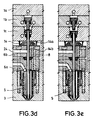
- FIG. 3a to 3e shows a schematic axial section through the multi-cavity injection moulding system according to Fig. 1 and 2 for an injection nozzle 5 in different phases of an injection moulding cycle.
- Fig. 3a shows the injection moulding system at the beginning of an injection moulding cycle.
- the gate 12 of the moulding cavity plate 3 is closed by the valve pin 9, and the reception piston 36 is, consequently, in a lower end position corresponding to the closed end position of the valve pin 9.
- the control passage 44 for the hydraulic fluid which is provided in the backplate 1b and which communicates with the cylinder space 39, has applied thereto a hydraulic pressure which is higher than that of the control passage 43 provided in the third backplate 1c.
- the value of the hydraulic control pressure within the control passage 43 can correspond to the control pressure within the control passage 46, which is provided in the first backplate 1a and which is used for the stop piston 41.
- the hydraulic pressure within the additional control passage 45 of the second backplate 1b can be maintained at the level of the control pressure within the hydraulic passage of the third backplate 1c and of the first backplate 1a in this phase.
- the control passages 43, 45, 46 are preferably in a pressure-relief state, whereas the control passage 44 has a supply pressure applied thereto.
- the valve pin 9 extends from the location where it is received in the reception piston 36 through the guide sleeve 14, which is arranged between the lower backplate 1c and the second hot runner means 6b and which has, on the one hand, an annular recess 14a for receiving therein the heads of the screws 8 for fixing and screw-fastening the injection nozzles 5 to the lower, first hot runner means 6a and, on the other hand, a cylindrical tubular projection 14b by means of which said guide sleeve 14 engages the respective axial bore 17, which forms an extension of the respective central melt bore 10 of each injection nozzle 5 and which extends through the hot runner manifolds 6a, 6b as well as through the sealing sleeve disc 13 by means of which said hot runner means are spaced, said tubular projection 14b being also used for centering the guide sleeve 14.
- the tubular projection 14b also serves to seal the axial bore 17 with respect to the hydraulic actuating device 15 and to deflect the melt flow of the second plastic material, which comes from the hot runner 24, into the axial bore 17 leading to the central melt bore 10.
- the guide sleeve 14 is used as an axial pressure reception sleeve against the lower, third backplate 1c in cases in which thermal expansion of the two hot runner means 6a, 6b occurs.
- Fig. 3a to 3e show also clearly how the hot runner plates 6a, 6b are fastened by means of screws to the moulding cavity plate 3 (screws 47) and how the respective injection nozzle 5 is installed in the moulding cavity plate 3 as well as how the melt of the first plastic material is distributed through the respective hot runner 19 and the inclined guide section 19a leading to the recess 27 at the back of the injection nozzle 5 and the front end face 18 of the first hot runner manifold 6a, respectively. Moreover, it is shown how the melt of the first plastic material is further convezed through the rear melt passages 28 to the first and second melt bores 29a, 29b of the nozzles.
- 3a to 3e shows only one of the two first and second melt bores 29a, 29b, which are arranged at radially equal distances from the central melt bore 10 (cf., however, Fig. 9).
- the melt bores 29a, 29b open into the annular space 30 in the nozzle tip, whereas the central melt bore 10 extends directly opposite to the gate 12 in the opening 34 of the nozzle mouthpiece 35, which is controlled by the tip of the valve pin 9 and which contains the tip end 32a of the heating element 32.
- thermocouple 70 is used as a signal transmitter for effecting temperature control of the injection nozzle 5, said thermocouple 70 extending up to and into the front end of said injection nozzle 5.
- Fig. 3a the gate 12 is closed by the valve needle 9, the hydraulic pressure in the control passages 43, 45 and 46 is preferably switched off, whereas a supply pressure is applied to the control passage 44.
- the stop piston 41 in the second backplate 1b is thus biased towards its lower end position so that the stop projection 42 projects into the cylinder space 39 of the third backplate 1c as far as possible and defines a stop means for the reception piston 36, which includes the rear end 16 of the valve pin 9 and which is urged rearwards by the pressure applied by the control passage 43.
- valve pin 9 In this intermediate position of the valve pin 9, which is determined by the pressure difference between the control passages 43 and 46c in connection with the stop piston 41, said valve pin 9 leaves the gate 12 open, whereas the opening 34 of the central melt bore in the heated nozzle mouthpiece 35 remains closed (cf. Fig. 9) and the first plastic melt is injected, under pressure and volume control, from the annular space 30 into the moulding cavity so as to form a basic layer of the injection moulded part.
- Fig. 3c The next phase of the injection moulding cycle is shown in Fig. 3c, where the valve pin 9 is located in its completely open position, i.e. in a rear end position.
- the same phase is indicated in Fig. 9 by the upper position of the tip end 11 of the valve pin 9, which is outlined by a broken line. This position is determined by the upper end position of the stop piston 41 provided with the stop projection 42 on which the reception piston 36 still abuts.
- the control passages 44 and 46 are in a pressure-relief state, whereas a supply pressure within the control passages 43 and 45 biases the stop piston 41 and the reception piston 36, respectively, towards their upper end positions. While effecting pressure and volume control of the second melt of the second plastic material with respect to the melt pressure of the first plastic material, the core layer (barrier layer), which forms part of the injection moulded part and which consists of the second plastic material, is, in the course of this phase, injected through the gate 12 into the moulding cavity, essentially without any mixing with the first plastic material.
- valve pin 9 is again advanced into the intermediate position according to Fig. 3b by re-exchanging the hydraulic pressure loads between the control passage 46 and the control passage 45 and by advancing the stop piston 41 to its lower end position, the control pressure applied to the control passages 43 to 46 corresponding to that explained in connection with Fig. 3b.
- the opening 34 and the valve pin 9 have provided between them a gap creating (either by means of a continuous annular gap or by means of circumferentially spaced longitudinal recesses in the inner circumferential surface of the opening 16 and/or in the outer circumferential surface of the valve pin 9) conditions of such a nature that, when the valve pin 9 is advanced to its closing end position, the melt, which is present below the tip 11 of the valve pin 9, can flow back between the opening 16 and the valve pin 9 in a direction opposite to the direction of valve pin movement.
- the valve pin control timing is essentially determined by the flow resistance generated in the course of this process.
- the injection moulding cycle is terminated while maintaining the injection moulding pressure for the purpose of melt compacting for a short period of time and by closing the gate 12 by the valve pin 9, as shown in Fig. 3e, which corresponds to Fig. 3a.
- the pressure in the control passages 43, 45, 46 is relieved, whereas the control passage 44 has applied thereto a supply pressure (closing pressure).
- a third plastic material can be provided as an adhesive in the case of the present method, said adhesive being effective between an inner core material layer (second plastic material) and the basic plastic material (first plastic material) surrounding said core material layer at least partially.
- the above-explained embodiment of the multi-cavity injection moulding system may, for example, by modified by providing a feed system by means of which the melt stream of the second plastic material has circumferentially applied thereto a thin film of a third plastic material showing a strong inclination to cross-link with the first as well as with the second plastic material and improving the connection between these plastic materials within the finished injection moulded part.
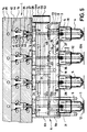
- Figures 4 to 8e show a multi cavity injection moulding system again designed for simultaneous injection moulding of eight injection moulded parts, each injection moulded part comprising three components, i.e. a first plastic material as a base and as a cover layer material, a second plastic material as a core or barrier layer material, and a third plastic material, the latter causing an intimate connection of the first and second plastic materials so as to form an integral structure of materials and being arranged between the first and second plastic materials.
- a first plastic material as a base and as a cover layer material
- a second plastic material as a core or barrier layer material
- a third plastic material the latter causing an intimate connection of the first and second plastic materials so as to form an integral structure of materials and being arranged between the first and second plastic materials.
- the multi-cavity injection moulding system according to this second embodiment is provided for the purpose of producing injection-moulded parts, which integrally comprise three plastic materials, a first plastic melt of a first plastic material, a second plastic melt of a second plastic material and a third melt of a third plastic material being processed in one injection cycle.
- the second plastic material which defines a barrier layer in the first plastic material, can also be formed merely in a part of the cross-section (e.g. in a central section thereof).
- the first melt is fed via a central, first supply passage 21 extending through the backplate arrangement 1 a central passage insulating sleeve 21b, the central sleeve 22 in the second hot runner manifold 6b and the sealing sleeve 23 up to the point where it opens into one of the hot runners 19 of the first hot runner plate 6a.
- the pouring opening 20 for the first plastic material is provided with an annular flange 20a, which is fixed to the third backplate 1a of the backplate arrangement 1 by means of screws and which is followed by a passage sleeve arrangement 21a for the first supply passage 21, said passage sleeve arrangement 21a resting, in turn, on said second hot runner manifold 6b via a heated passage insulating sleeve 21b, which also seals the first supply passage 21 with respect to the second hot runner manifold 6b and which acts as a spacer between said hot runner plate 6b and said backplate arrangement 1.
- the passage insulating sleeve 21b which is not shown in a sectional view in these figures, has integrally provided therein a heating element, which is connected to an electric connection means 21c.
- the second and third plastic materials are supplied to the injection nozzles 5 through the second hot runner manifold 6b having, for this purpose, second and third hot runners 24, 48 which have the plastic material supplied thereto from the second and third inlet openings 25, 52 through the second hot runner manifolds 6b from the back thereof (pouring opening) 25) and from one side of said second hot runner manifold 6b (pouring opening 52), respectively, through an associated second supply passage 57 and a third supply passage 58, which are displaced relative to each other by essentially 90°.
- Fig. 4 elucidates, on the one hand, the arrangement pattern of the injection nozzles 5, the position and the structural design of the first, central pouring opening 20 for the first plastic material and of the second pouring opening 25 for the second plastic material as well as of the third pouring opening 52 for the third plastic material, and the rheologically balanced mode of guiding the respective plastic melt within the injection moulding system, as will be explained in detail hereinafter.
- Fig. 1 elucidates the heating structure for heating the hot runner system by means of heating element passages 60, 61 with heating elements 26 received in said passages, which provide essentially uniform heating of the hot runner system 6 in respective horizontal planes and the electric connections of which are provided with reference numerals 62 and 63 in Fig. 1. Further details, in particular details concerning the way in which the respective melt of one of the plastic materials is guided between the relevant pouring opening 20, 25, 52 and the injection nozzle 5 in question, will be explained in detail hereinbelow.
- the supply passages 57 and 58 are arranged such that they extend, in planes which are horizontally displaced relative to each other, up to and into the central area of the multi-cavity injection moulding system, and in said area they open into first and second axially spaced annular grooves 59a, 59b of the central sleeve 22.
- the third supply passage 58 for the third plastic melt is connected to a third annular groove 59d on the outer periphery of the central sleeve 22 via the second annular groove 59b of the central sleeve 22 and via a peripheral axial passage 59c, the third melt-distributing passages 48 of the second hot runner means 6b opening into said third annular groove 59d.
- the central sleeve 22 serves, on the one hand, as an axial passage sleeve for providing an extension of the first supply passage 21, which carries the melt of the first plastic material, towards the lower, first hot runner manifold 6a and, on the other hand, it also serves as a radial distributor sleeve for providing a connection between the second and third supply passages 57, 58 for the melts of the second and third plastic materials and the associated hot runners 24 and 48, which are provided on different levels in essentially parallel planes for distributing the second and third plastic materials among the injection nozzles 5.
- the hot runner means 6a and 6b have provided between them, again in the central area, a sealing sleeve 23, which guides the relevant section of the first supply passage 21 and which is arranged subsequently to the central sleeve 22.
- the second hot runner means 6b has second and third hot runners 24, 48 for the second and third plastic materials, said hot runners 24, 48 being connected to the valve pin axial bore 17 for each injection nozzle 5 for the purpose of feeding the second and third plastic materials into the central melt bore 10 of each injection nozzle 5 - which contains also the valve needle 9 - via the valve needle axial bore 17 in a manner which is shown in detail in Fig. 3 as well as in Fig. 5a to 5e and which will be explained more precisely hereinbelow.
- the pouring openings 25 and 52 which are arranged on the second hot runner manifold 6b such that they are provided on different levels and displaced by approx.
- the hot runner manifolds 6a, 6b are heated via the electric connections 62, 63 in the conventional manner by means of integrally embedded heating elements 26, which are bonded to said hot runner means 6a, 6b, (cf. Fig. 1 and 2), so as to guarantee - depending on the selected combination of materials for the first plastic material on the one hand and for the second and third plastic materials on the other - an optimum temperature of the melt along the hot runners 19, 24 and 48.
- the temperature of each hot runner manifold 6a, 6b can be different, and said temperatures can be controlled in connection with thermocouples, which are not shown in this embodiment.
- the maximum viscosity of the melt of the third plastic material corresponds preferably to the viscosity of the second plastic material, and the viscosity of the second plastic material, which preferably defines a core layer of the injection moulded part, is preferably equal to or lower than the viscosity of the first plastic material, which, serving as a basic material, embeds the core material.
- the hot runner manifolds 6a, 6b Due to the sealing and sliding fit between the hot runner manifolds 6a, 6b, which is guaranteed by means of the sealing sleeve discs 13, 23 in connection with the passage insulating sleeve 21b, said hot runner manifolds 6a, 6b can carry out thermal expansion movements relative to each other as already mentioned.
- the distribution of the first and second substantial melts corresponds to that of the first embodiment.
- the second melt hot runners 24 open into the axial bore 17, which also accommodates therein the valve pin 9 of the second manifold 6b.
- the axial bore 17 opens into a guide bore of a guide sleeve 14 for the valve needle 9, said guide sleeve 14 engaging the upper end of said axial bore 17 by means of a tubular projection 14b.
- the tubular projection 14b serves to seal the axial bore 17 in the direction of a hydraulic actuating means 15 for each valve pin as well as to deflect the melt of the second plastic material from the respective melt-distributing passage 24 into the axial bore 17 leading to the melt bore 10 of each injection nozzle 5, the engagement end of the tubular projection 14b being, for this purpose, provided with an inclined surface facing the mouth of the respective hot runner 24.
- the hot runner 48 for the third plastic melt extend through the second hot runner manifold 6b in a horizontal plane parallel and downwards of the plane of the hot runners 19 up to a point which is located close to the respective axial bores 17.
- end face 50 of the second hot runner manifold 6b has provided therein a counter-annular passage 51b, which corresponds to the annular passage 51a in the sealing sleeve disc 13 and into which an end section 48a of the respective third hot runner48 terminates.
- the annular passage 51a in the sealing sleeve disc 13 and the counterannular passage 51b in the second hot runner manifold 6b define, in combination, preferably a full-circle cross-section, and, for the purpose of connecting the annular recess 51a, 51b to the central bore 53 in the sealing sleeve disc 13, there is provided at least one introduction gap of preferably selectable width, said introduction gap being used for uniformly applying to an outer peripheral area of the melt flow of second plastic material in the central bore 53 the third plastic material from the annular recess 51a, 51b in the area of a boundary surface between the second hot runner manifold 6b and the sealing sleeve disc 13.
- each of said hot runners 48 is provided with an axial section 48a extending axially parallel to the axial bore 17.
- the third plastic material is added to the second plastic material, at a location downstream of the point where said second plastic material flows into the axial bore 17, so as to form a controlled, peripheral melt film close to a respective injection nozzle 5, it is possible to feed the second and third plastic materials as composite materials to the central melt bore 10 of each injection nozzle 5 and from said injection nozzle to a moulding cavity for forming, in an injection moulded part, a core or barrier layer consisting of the second plastic material and an adhesive connection layer provided between said first and second plastic materials and consisting of the third plastic material.
- the third plastic material in the annular recesses 51a, 51b can be maintained in a depressurized state to a very large extent and the vacuum generated in the introduction gap by the melt flow of the second plastic material through the axial bore 17 and the central bore 53 can be sufficient to produce a suction effect sucking the third plastic material from the annular recesses 51a, 51b so as to form a thin coating on the melt flow of the second plastic material.
- the vacuum generated in the introduction gap by the melt flow of the second plastic material through the axial bore 17 and the central bore 53 can be sufficient to produce a suction effect sucking the third plastic material from the annular recesses 51a, 51b so as to form a thin coating on the melt flow of the second plastic material.
- the cross-sectional configuration of the annular recesses 51a, 51b can vary within wide limits and may, for example, also include a melt storage space which opens into an annular nozzle gap, which, in turn, communicates with the axial bore 17 and the central bore 53, respectively.
- the material used as first plastic material is preferably polypropylene
- the material used as second plastic material is preferably polyamide (nylon)
- the material used as third plastic material is preferably ethylene-vinyl-alcohol
- the injection moulding system and the method according to the present invention are, however, not limited to the use of such a combination of materials. It is, for example, also possible to use ethylene-vinyl-alcohol as the second plastic material and ethylene-vinyl-acetate as the third plastic material.
- the second plastic material (barrier layer) can also extend only partially in the first plastic material, and in a sub-area of the cross-section of the injection moulded part it can extend such that it is at least partially embedded in said first plastic material.
- the materials are supplied to the injection nozzles 5 while effecting pressure and/or volume control of the melts of said first, second and third plastic materials, the percentage of the third plastic material being lower than the percentages of the first and second plastic materials and the second plastic material being normally provided in smaller amounts than the first plastic material.
- this finds expression in a flow cross-section of the third melt-distributing passage 48 for the third plastic material which is reduced in size in comparison with the melt distributing passages 19, 24 for the first and second plastic materials.
- reference numeral 31 is used for referring to the electric connections for a heating element 32, which is provided in each of the heated injection nozzles 5 of the multi-cavity injection moulding system.
- the valve pin 9 extends from the location where it is received in the reception piston 36 through the guide sleeve 14, which is arranged between the lower backplate 1c and the second hot runner manifolds 6b and which has, on the one hand, an annular recess 14a for receiving therein the heads of the screws 8 used for fastening the guide sleeve to the second hot runner manifold 6b and, on the other hand, a cylindrical tubular projection 14b by means of which said guide sleeve 14 engages the resepctive axial bore 17, is also used for centering said guide sleeve 14.
- the tubular projection 14b also serves to seal the axial bore 17 with respect to the hydraulic actuating device 15 and the deflect the melt flow of the second plastic material, which comes from the hot runners 24, into the axial bore 17 leading to the central melt bore 10.
- the guide sleeve 14 is used as an axial pressure reception sleeve against the lower, third backplate 1c.
- each sealing sleeve disc 13 which forms simultaneously an annular distributing member for the third plastic material towards the axial bore 17, is received as an insert in the first hot runner manifold 6a, which is provided with a corresponding insertion recess.
- respective tapped holes are provided, which extend through the hot runner manifold 6a in the vertical direction and which serve to receive therein fastening screws 8 for securing the respective associated injection nozzle 5 to the first hot runner manifold 6a.
- polypropylene is used as the first plastic material of the injection moulded part defining the basic material
- polyamide provided with a connection layer of ethylene-vinyl-alcohol
- ethylene-vinyl-alcohol is injected as a second plastic material for forming an oxygen-impervious barrier layer.
- ethylene-vinyl-alcohol is injected as a second plastic material, said substance being then preferably used in connection with ethylene-vinyl-acetate as a third plastic material.
- the present invention is, of course, not limited to these materials, but it is just as well possible to use other suitable combinations of materials, which contain, for example, ethylene-vinyl-alcohol, depending on the respective fields of use and the processibility of the materials in an integral injection moulding process.
- a composite material consisting of the second and third plastic materials should, however, have a viscosity which is, at the most, equal to that of the first palstic material and which should preferably be lower than the viscosity of the first plastic material.
- injection moulding system limited to the use of needle valve gating, although this type of gating turns out to be particularly advantageous.
- this type of valve gating would permit separate injection of the various plastic materials while effecting volume and pressure control of the melt pressure of the melts of said first and second plastic materials in separate melt passage means.
Landscapes
- Engineering & Computer Science (AREA)
- Manufacturing & Machinery (AREA)
- Mechanical Engineering (AREA)
- Injection Moulding Of Plastics Or The Like (AREA)
- Moulds For Moulding Plastics Or The Like (AREA)
Claims (15)
- Mehrfachform-Spritzgießeinrichtung mit einer Rückplattenanordnung (1), einer Heißkanalverteileranordnung mit einem ersten Heißkanalverteiler (6a) für ein erstes Kunststoffmaterial und einem zweiten Heißkanalverteiler (6b) für zumindest ein weiteres Kunststoffmaterial, und Spritzdüsen (5), die zur Zuführung der Kunststoffmaterialien zu zugehörigen, in einer Hohlraumplatte (3) ausgebildeten Hohlräumen an der Heißkanalverteileranordnung angebracht sind, dadurch gekennzeichnet, daß die Heißkanalverteiler (6a, 6b) Verteilerplatten bilden, die im wesentlichen parallel hintereinanderliegend zwischen der Hohlraumplatte (3) und der Rückplattenanordnung (1) angeordnet sind, wobei der erste, die Spritzdüsen (5) tragende Heißkanalverteiler (6a), vor dem zweiten Heißkanalverteiler (6b) angeordnet ist, und daß ein zentraler Schmelzenzuführkanal (21) für das erste Kunststoffmaterial sich von einer zentralen Eingießöffnung (20) auf der Rückseite der Rückplattenanordnung (1) durch die Rückplattenanordnung (1) sowie durch den zweiten Heißkanalverteiler (6b) zu dem ersten Heißkanalverteiler (6a) erstreckt und in im wesentlichen horizontal darin verlaufende, verzweigte Heißkanäle (19) mündet, die mit dem zugehörigen Schmelzenkanal (29a, 29b) der jeweiligen Spritzdüsen (5) verbunden sind, und daß eine Eingießöffnung (25) für das zweite Kunststoffmaterial seitlich an dem zwischen dem ersten Heißkanalverteiler (6a) und der Rückplattenanordnung (1) angeordneten zweiten Heißkanalverteiler (6b) vorgesehen ist, wobei die zweite Eingießöffnung (25) mit verzweigenden Heißkanälen (24) verbunden ist, die sich im wesentlichen horizontal erstreckend mit Axialbohrungen (17) verbunden sind, die ihrerseits den zentralen Schmelzenkanal (10) der jeweiligen Spritzdüse (5) nach rückwärts verlängern.
- Mehrfachform-Spritzgießeinrichtung nach Anspruch 1, dadurch gekennzeichnet, daß die Heißkanalverteiler (6a, 6b) relativ zueinander festgelegt und Dichthülsenscheiben (13) zwischen den Heißkanalverteilern (6a, 6b) angeordnet sind, wobei die Dichthülsenscheiben (13) einen Teil der Axialbohrungen (17) bilden, die die zentralen Schmelzenbohrungen (10) der Spritzdüsen (5) nach rückwärts durch die Heißkanalverteiler (6a, 6b) hindurch verlängern.
- Mehrfachform-Spritzgießeinrichtung nach mindestens einem der Ansprüche 1 oder 2, dadurch gekennzeichnet, daß eine Dichtungshülse (23), die einen Teil des zentralen Schmelzenzuführkanales (21) für das erste Kunststoffmaterial bildet, zwischen dem ersten und dem zweiten Heißkanalverteiler (6a, 6b) angeordnet ist.
- Mehrfachform-Spritzgießeinrichtung nach mindestens einem der Ansprüche 1 bis 3, dadurch gekennzeichnet, daß die Heißkanäle (19) des die Spritzdüsen (5) tragenden, vorderen Heißkanalverteilers (6a) geneigte, in eine Ausnehmung (27) mündende Führungsabschnitte (19a) aufweisen, wobei die Ausnehmungen (27) in gleicher Weise in der Vorderseite (18) des die zugehörigen Spritzdüsen (5) tragenden Heißkanalverteilers (6a) wie in einer an der Vorderseite des Heißkanalverteilers (6a) anliegenden Rückwand der Spritzdüse (5) vorgesehen sind, wobei die in der Rückseite der Spritzdüse (5) vorgesehene Ausnehmung (27) mit dem Schmelzenkanal (29a, 29b) für das erste Kunststoffmaterial der Spritzdüse (5) verbunden ist.
- Mehrfachform-Spritzgießeinrichtung nach Anspruch 4, dadurch gekennzeichnet, daß die Ausnehmungen (27) für benachbarte Spritzdüsen (5) paarweise einander gegenüberliegend angeordnet sind, und die geneigten Führungsabschnitte (19a) paarweise symmetrisch den jeweiligen Heißkanal (19) mit den zugehörigen, gegenüberliegenden Ausnehmungen (27) eines Paares zugehöriger Spritzdüsen (5) verbindet.
- Mehrfachform-Spritzgießeinrichtung nach mindestens einem der Ansprüche 1 bis 5, dadurch gekennzeichnet, daß der zweite Heißkanalverteiler (6b) eine Zentralhülse (22) aufweist, die mit der zentralen, ersten Eingießöffnung (20) durch einen ersten Schmelzenzuführkanal (21) für das erste Kunststoffmaterial verbunden ist, und die einen Durchgangskanal für den Transport des ersten Kunststoffmateriales zu dem ersten Heißkanalverteiler (6a) sowie eine Verteilerhülse in dem zweiten Heißkanalverteiler (6b) für das zweite und dritte Kunststoffmaterial bildet.
- Mehrfachform-Spritzgießeinrichtung nach Anspruch 6, dadurch gekennzeichnet, daß ein zweiter Zuführkanal (57) für das zweite Kunststoffmaterial sich von einer, seitlich an dem zweiten Heißkanalverteiler (6b) angeordneten zweiten Eingießöffnung (25) zu einer Zentralhülse (22) erstreckt, und daß ein dritter Zuführkanal (58) für das dritte Kunststoffmaterial sich von einer seitlich an dem zweiten Heißkanalverteiler (6b) angeordneten dritten Eingießöffnung (52) zu einer Zentralhülse (22) erstreckt, daß die ersten, zweiten und dritten Zuführkanäle (21, 25, 52) sich im wesentlichen in einem Winkel von 90° zueinander erstrecken, und daß die Zentralhülse (22) mit ersten und zweiten umlaufenden, voneinander getrennten Ausnehmungen (59a, 59b) versehen ist, die den zweiten Zuführkanal (57) mit den sich im wesentlichen horizontal erstreckenden, für das zweite Kunststoffmaterial vorgesehenen zweiten, verzweigten Heißkanälen (24) sowie den dritten Zuführkanal (58) mit den dritten, sich im wesentlichen horizontal durch den zweiten Heißkanalverteiler (6b) erstreckenden und für das dritte Kunststoffmaterial vorgesehenen dritten verzweigten Heißkanälen (48) verbinden, wobei die zweiten und dritten Heißkanäle (24, 48) des zweiten Heißkanalverteilers (6b) sich so im wesentlichen in horizontalen, voneinander beabstandeten Ebenen erstrecken, daß die zweiten Heißkanäle (24) in Axialbohrungen (17) münden, die die zentralen Schmelzenbohrungen (10) der Spritzdüsen (5) an einer Stelle stromauf der Stelle, wo die dritten Heißkanäle (48) in die Axialbohrungen (17) münden, nach rückwärts durch den ersten und zweiten Heißkanalverteiler (6a, 6b) verlängern.
- Mehrfachform-Spritzgießeinrichtung nach Anspruch 7, dadurch gekennzeichnet, daß die umlaufenden Ausnehmungen axial beabstandete, umlaufende, ringförmige Nuten (59a, 59b, 59d) sind.
- Mehrfachform-Spritzgießeinrichtung nach mindestens einem der Ansprüche 6 bis 8, dadurch gekennzeichnet, daß die Heißkanalverteiler (6a, 6b) relativ zueinander festgelegt sind, daß die Dichthülsenscheiben (13) zwischen den Heißkanalverteilern (6a, 6b) angeordnet sind, wobei die Dichthülsenscheiben (13) einen Abschnitt der Axialbohrungen (17), die die zentrale Schmelzenbohrung (10) der jeweiligen Spritzdüse (5) nach rückwärts durch die Heißkanalverteiler (6a, 6b) verlängern, bilden, wobei die Dichthülsenscheiben (13) mit einer Gleitfläche (49) an einer, einen Teil des zweiten Heißkanalverteilers (6b) bildenden, zu dem ersten Heißkanalverteiler (6a) weisenden, vorderen Endseite (50) anliegt, daß die Gleitfläche (49) mit einer Umfangsausnehmung (51a) versehen ist, die mit dem dritten Schmelzenverteilkanal (48) verbunden ist und mit dem Axialkanal (17) kommuniziert, und daß die vordere Endseite (50) des zweiten Heißkanalverteilers (6b) mit einer ringförmigen Ausnehmung (51b) versehen ist, die den Umfangsausnehmungen (51a) entsprechen, und die mit dem dritten Heißkanal (48) über einen vertikalen Zweigkanal (48a) verbunden ist.
- Mehrfachform-Spritzgießeinrichtung nach mindestens einem der Ansprüche 6 bis 9, dadurch gekennzeichnet, daß die Dichthülse (23) zwischen der einen Teil des zentralen Schmelzenzuführkanales (21) für das erste Kunststoffmaterial bildenden Zentralhülse (22) und dem ersten vorderen Heißkanalverteiler (6a) vorgesehen ist, wobei das erste Kunststoffmaterial durch die Dichthülse (23) den sich im wesentlichen horizontal durch den ersten Heißkanalverteiler (6a) erstreckenden ersten, verzweigten Heißkanälen (19) zugeführt wird, die über geneigte Heißkanalabschnitte (19a) mit den Schmelzenbohrungen (29a, 29b) der Spritzdüsen (5) für das erste Kunststoffmaterial verbunden sind, wobei die Schmelzenbohrungen (29a, 29b) zu der zentralen Schmelzenbohrung (10) radial versetzt sind.
- Mehrfachform-Spritzgießeinrichtung nach mindestens einem der Ansprüche 1 bis 10, dadurch gekennzeichnet, daß jede Spritzdüse (5) ein integral mit dieser ausgebildetes Isolierflanschteil (7) aufweist, das die Spritzdüse (5) mit dem ersten, vorderen Heißkanalverteiler (6a) verbindet, daß eine Ventilstiftführungsbuchse (14) zwischen dem zweiten, hinteren Heißkanalverteiler (6b) und der Rückplattenanordnung (1) in einem Führungsbereich jeder der Spritzdüsen (5) vorgesehen ist, zum Führen eines in der zentralen Schmelzenbohrung (10) jeder Spritzdüse (5) axial bewegbar aufgenommenen Ventilstiftes (9), daß die Spritzdüsen (5) mit den Führungsbuchsen (14) und den Heißkanalverteilern (6a, 6b) durch Befestigungsschrauben (8) unter Bildung einer Baueinheit verbunden sind, daß die Heißkanalverteiler (6a, 6b) mittels Befestigungsschrauben (47) an der Hohlraumplatte (3) befestigt sind, und daß die Rückplattenanordnung (1) an der Hohlraumplatte (3) mittels Bolzen befestigt ist.
- Mehrfachform-Spritzgießeinrichtung nach mindestens einem der Ansprüche 1 bis 11, dadurch gekennzeichnet, daß die Schmelzenkanäle für das erste Kunststoffmaterial in jeder Spritzdüse (5) erste und zweite Schmelzenbohrungen (29a, 29b) aufweisen, die sich axial durch die Spritzdüse (5) zu einem Ort erstrecken, wo sie in einen Schmelzenaufnahmeraum (30) in der Düsenspitze der Spritzdüse (5) münden, und die sich an der Rückseite der Spritzdüse zur Verbindung mit der Ausnehmung (27) öffnen, daß die zentrale Schmelzenbohrung (10) für das zweite Kunststoffmaterial sich entlang der zentralen Längsachse der Spritzdüse (5) erstreckt, und daß der in der zentralen Schmelzenbohrung (10) aufgenommene Ventilstift (9) sich durch die die zentrale Schmelzenbohrung (10) verlängernde Axialbohrung (17) und durch die Ventilstiftführungsbuchse (14) erstreckt, wobei das hintere Ende (16) des Ventilstiftes (9) in einer in der Rückplattenanordnung (1) vorgesehenen, hydraulischen Betätigungsvorrichtung (15) aufgenommen ist.
- Mehrfachform-Spritzgießeinrichtung nach Anspruch 12, dadurch gekennzeichnet, daß das hintere Ende (16) des Ventilstiftes (9) in einem Kolben (36) aufgenommen ist, der dichtend in einem Zylinder (39) der ersten Rückplatte (1c) der Rückplattenanordnung (1) angeordnet ist, wobei der Zylinder (39) geeignet ist, unabhängig durch auf beide Seiten des Kolbens (36) wirkenden Fluiddruck betätigt zu werden, und daß ein Steuerkanal (43) in der ersten Rückplatte (1c) mit dem Zylinder (39) verbunden ist.
- Mehrfachform-Spritzgießeinrichtung nach Anspruch 13, dadurch gekennzeichnet, daß die Rückplattenanordnung (1) zusätzlich zu der ersten Rückplatte (1c) eine zweite sowie eine hintere, dritte Rückplatte (1b, 1a) aufweist, daß die zweite Rückplatte (1b), die die Zylinder (39) der ersten Rückplatte (1c) abdichtet, einen in einem zugehörigen Zylinder (40) gleitbewegbar angeordneten Anschlagkolben (41) aufnimmt, wobei ein zylindrisches Anschlagteil (42) des Anschlagkolbens (41) in den Zylinder (39) der ersten Rückplatte (1c) hineinragt, daß die Zylinder (40) der mit dem Anschlagkolben (41) versehenen, zweiten Rückplatte (1b) durch die mit hydraulischen Steuerkanälen (46) zur Steuerdruckbeaufschlagung des Anschlagkolbens (41) versehene, hintere dritte Rückplatte (1a) abgedeckt ist, daß die zweite Rückplatte (1b) Steuerkanäle (44, 45) zur Steuerdruckbeaufschlagung des Anschlagkolbens (41) und eines Aufnahmekolbens (36) für das hintere Ende (16) des Ventilstiftes (9) aufweist, und daß die dritte Rückplatte (1) unter Einschluß der ersten und zweiten Rückplatten (1b, 1c) mittels Bolzen an der Hohlraumplatte (3) befestigt ist.
- Mehrfachform-Spritzgießeinrichtung nach mindestens einem der Ansprüche 6 bis 14, dadurch gekennzeichnet, daß jede Spritzdüse (5) mit einem integral mit dieser verbundenen Heizelement (32) versehen ist, das sich mit einem Ende (32a) zu der Düsenspitze in der jeweiligen Spritzdüse (5) erstreckt und eine Öffnung (34) der zentralen Schmelzenbohrung (10) umgibt.
Applications Claiming Priority (4)
| Application Number | Priority Date | Filing Date | Title |
|---|---|---|---|
| DE19904032500 DE4032500C2 (de) | 1990-10-12 | 1990-10-12 | Verfahren zur Herstellung eines Mehrkomponenten-Spritzgießteiles und Mehrfachform-Spritzgießeinrichtung |
| DE4032500 | 1990-10-12 | ||
| DE4032499 | 1990-10-12 | ||
| DE19904032499 DE4032499C2 (de) | 1990-10-12 | 1990-10-12 | Mehrfachform-Spritzgießeinrichtung |
Publications (2)
| Publication Number | Publication Date |
|---|---|
| EP0480223A1 EP0480223A1 (de) | 1992-04-15 |
| EP0480223B1 true EP0480223B1 (de) | 1995-08-30 |
Family
ID=25897670
Family Applications (1)
| Application Number | Title | Priority Date | Filing Date |
|---|---|---|---|
| EP91116142A Expired - Lifetime EP0480223B1 (de) | 1990-10-12 | 1991-09-23 | Mehrfachform-Spritzgiesssystem |
Country Status (6)
| Country | Link |
|---|---|
| EP (1) | EP0480223B1 (de) |
| JP (1) | JPH0687134A (de) |
| AT (1) | ATE127069T1 (de) |
| CA (1) | CA2052081C (de) |
| DE (1) | DE69112559T2 (de) |
| DK (1) | DK0480223T3 (de) |
Families Citing this family (21)
| Publication number | Priority date | Publication date | Assignee | Title |
|---|---|---|---|---|
| CA2032294A1 (en) * | 1990-12-17 | 1992-06-18 | Jobst Ulrich Gellert | Thermal valve gated injection molding apparatus with melt distribution plate |
| IT1254989B (it) * | 1992-06-23 | 1995-10-11 | Dante Siano | Dispositivo per la coiniezione in punti distinti di uno stampo |
| EP0614744B1 (de) * | 1993-02-25 | 1998-11-04 | Sony Electronics Inc. | Giessvorrichtungen |
| CH685237A5 (de) * | 1993-10-06 | 1995-05-15 | Otto Hofstetter Ag Werkzeug Un | Spritzgiess-Formwerkzeug. |
| US5507637A (en) * | 1995-03-02 | 1996-04-16 | Husky Injection Molding Systems Ltd. | Hot runner sliding nozzle |
| NL1001417C2 (nl) * | 1995-10-13 | 1997-04-15 | Inter Tooling Services Bv | Inrichting voor het vervaardigen van holle kunststof voorwerpen. |
| DE19606045C2 (de) * | 1996-02-19 | 1997-11-27 | Krupp Ag Hoesch Krupp | Verfahren zum Spritzgießen von dreischichtigen Spritzlingen und Vorrichtung für die Durchführung des Verfahrens |
| ES2150254T3 (es) * | 1996-06-12 | 2000-11-16 | Hofstetter Ag Otto | Dispositivo de bloque distribuidor de coinyeccion con canales calientes. |
| CA2219235C (en) * | 1997-10-23 | 2006-12-12 | Mold-Masters Limited | Five layer injection molding apparatus having four position valve member actuating mechanism |
| US6228309B1 (en) | 1998-12-22 | 2001-05-08 | Husky Injection Molding Systems Ltd. | Method and apparatus for injection molding including valve stem positioning |
| US6561790B2 (en) | 2001-07-24 | 2003-05-13 | Husky Injection Molding Systems, Ltd. | Sealing member in an injection molding machine |
| US6752618B2 (en) | 2001-12-20 | 2004-06-22 | Mold-Masters Limited | Injection manifold having a valve pin guiding device |
| AU2003303887B2 (en) * | 2003-02-04 | 2007-04-26 | Husky Injection Molding Systems Ltd. | Hot runner manifold system |
| US20070122519A1 (en) * | 2005-11-28 | 2007-05-31 | Yudo Co. Ltd. | Apparatus for controlling resin amount in cylinders of injection molding machines |
| KR101031146B1 (ko) * | 2010-09-20 | 2011-04-27 | 허남욱 | 노즐 중심정렬기구를 구비한 사출금형장치 |
| CN104507658A (zh) * | 2012-07-12 | 2015-04-08 | 奥托门纳创新有限责任公司 | 具有主动阀销脱开的注射成型装置 |
| DE102019127960A1 (de) | 2019-10-16 | 2021-04-22 | Thermoplay S.P.A. | Spritzgusswerkzeug |
| CN112060493B (zh) * | 2020-09-15 | 2024-10-11 | 台州市一川模具有限公司 | 双注射口注塑模具落差行程阻断封胶机构 |
| CN112590093B (zh) * | 2020-11-25 | 2022-06-17 | 贵州红阳机械有限责任公司 | 一种端盖零件压制工艺的模具及应用 |
| CN114589885B (zh) * | 2022-03-08 | 2023-12-12 | 依润特工业智能科技(苏州)有限公司 | 一种挤出热流道系统 |
| CN116039012B (zh) * | 2023-01-09 | 2023-07-07 | 浙江恒道科技有限公司 | 一种多活塞气缸及控制方式 |
Family Cites Families (5)
| Publication number | Priority date | Publication date | Assignee | Title |
|---|---|---|---|---|
| FR893933A (fr) * | 1942-01-20 | 1944-11-14 | Procédé d'obtention de pièces à corps concentriques multiples pleins ou creux etmachine pour sa mise en oeuvre | |
| CA1252969A (en) * | 1986-10-15 | 1989-04-25 | Henry J. Rozema | Sealing and retaining bushing for injection molding |
| US4957682A (en) * | 1988-01-19 | 1990-09-18 | Kamaya Kagaku Kogyo Co., Ltd. | Method of injection molding a three-layered container |
| CA1280268C (en) * | 1988-09-30 | 1991-02-19 | Jobst Ulrich Gellert | Injection molding nozzle having nose portion with heating element encircling the bore and method |
| JPH02229017A (ja) * | 1989-01-13 | 1990-09-11 | Husky Injection Molding Syst Ltd | 射出成形法及び射出成形ノズル構造 |
-
1991
- 1991-09-23 DE DE69112559T patent/DE69112559T2/de not_active Expired - Lifetime
- 1991-09-23 AT AT91116142T patent/ATE127069T1/de not_active IP Right Cessation
- 1991-09-23 EP EP91116142A patent/EP0480223B1/de not_active Expired - Lifetime
- 1991-09-23 CA CA002052081A patent/CA2052081C/en not_active Expired - Fee Related
- 1991-09-23 DK DK91116142.0T patent/DK0480223T3/da active
- 1991-10-09 JP JP3290900A patent/JPH0687134A/ja active Pending
Also Published As
| Publication number | Publication date |
|---|---|
| CA2052081A1 (en) | 1992-04-13 |
| DE69112559T2 (de) | 1996-02-01 |
| DE69112559D1 (de) | 1995-10-05 |
| DK0480223T3 (da) | 1995-12-27 |
| CA2052081C (en) | 2002-11-12 |
| ATE127069T1 (de) | 1995-09-15 |
| EP0480223A1 (de) | 1992-04-15 |
| JPH0687134A (ja) | 1994-03-29 |
Similar Documents
| Publication | Publication Date | Title |
|---|---|---|
| US5223275A (en) | Multi-cavity injection moulding system | |
| EP0480223B1 (de) | Mehrfachform-Spritzgiesssystem | |
| CA1291610C (en) | Coinjection of hollow articles and preforms | |
| US6274075B1 (en) | Five layer injection molding apparatus having four position valve member actuating mechanism | |
| US7175419B2 (en) | Hot runner co-injection nozzle | |
| CA2247867C (en) | Multiple gating nozzle | |
| CA2255613C (en) | Process and apparatus for forming plastic articles | |
| JP4368452B2 (ja) | 射出成形機、複数材料射出成形機、射出成形機用シューティングポット作動アセンブリ、及び複数材料射出成形機用シューティングポットアクチュエータ | |
| US4808101A (en) | Tri-injection of hollow articles | |
| EP0614744B1 (de) | Giessvorrichtungen | |
| EP0911135B1 (de) | Spritzgiessvorrichtung mit einem Schmelzekanal durch die Stirnseite des Stiftes | |
| EP0911138B1 (de) | Spritzgiessvorrichtung mit Schmelzübertragungsbuchsen zwischen die Kanalverteiler | |
| EP0911136B1 (de) | Spritzgiessvorrichtung mit Angussdüsen und Verfahren zum Formen von fünfschichtigen Gegenständen | |
| EP1163096B1 (de) | Vorrichtung und verfahren zum mehrschichtspritzgiessen | |
| US4004871A (en) | Mold gate apparatus | |
| EP0916468B1 (de) | Spritzgiessvorrichtung mit Schmelzübertragungs- und Verteilerbuchsen | |
| CA2462150C (en) | Multiple gating nozzle | |
| EP1163098B1 (de) | Vorrichtung und verfahren zum mehrschichtspritzgiessen | |
| KR100304070B1 (ko) | 플라스틱제품의 성형방법 및 장치 | |
| JPH08118426A (ja) | ホットランナ装置 | |
| JPH049144Y2 (de) |
Legal Events
| Date | Code | Title | Description |
|---|---|---|---|
| PUAI | Public reference made under article 153(3) epc to a published international application that has entered the european phase |
Free format text: ORIGINAL CODE: 0009012 |
|
| AK | Designated contracting states |
Kind code of ref document: A1 Designated state(s): AT BE CH DE DK ES FR GB GR IT LI LU NL SE |
|
| 17P | Request for examination filed |
Effective date: 19921009 |
|
| 17Q | First examination report despatched |
Effective date: 19940127 |
|
| GRAA | (expected) grant |
Free format text: ORIGINAL CODE: 0009210 |
|
| AK | Designated contracting states |
Kind code of ref document: B1 Designated state(s): AT BE CH DE DK ES FR GB GR IT LI LU NL SE |
|
| PG25 | Lapsed in a contracting state [announced via postgrant information from national office to epo] |
Ref country code: GR Free format text: LAPSE BECAUSE OF FAILURE TO SUBMIT A TRANSLATION OF THE DESCRIPTION OR TO PAY THE FEE WITHIN THE PRESCRIBED TIME-LIMIT Effective date: 19950830 Ref country code: ES Free format text: THE PATENT HAS BEEN ANNULLED BY A DECISION OF A NATIONAL AUTHORITY Effective date: 19950830 |
|
| REF | Corresponds to: |
Ref document number: 127069 Country of ref document: AT Date of ref document: 19950915 Kind code of ref document: T |
|
| ITF | It: translation for a ep patent filed | ||
| REF | Corresponds to: |
Ref document number: 69112559 Country of ref document: DE Date of ref document: 19951005 |
|
| ET | Fr: translation filed | ||
| REG | Reference to a national code |
Ref country code: DK Ref legal event code: T3 |
|
| PLBE | No opposition filed within time limit |
Free format text: ORIGINAL CODE: 0009261 |
|
| STAA | Information on the status of an ep patent application or granted ep patent |
Free format text: STATUS: NO OPPOSITION FILED WITHIN TIME LIMIT |
|
| 26N | No opposition filed | ||
| REG | Reference to a national code |
Ref country code: GB Ref legal event code: IF02 |
|
| REG | Reference to a national code |
Ref country code: CH Ref legal event code: PUE Owner name: MOLD-MASTERS (2007) LIMITED Free format text: JOBST ULRICH GELLERT#7A PRINCE STREET#GEORGETOWN/ONTARIO (CA) -TRANSFER TO- MOLD-MASTERS (2007) LIMITED#233 ARMSTRONG AVENUE#GEORGETOWN ON L7G4X5 (CA) |
|
| REG | Reference to a national code |
Ref country code: GB Ref legal event code: 732E |
|
| NLS | Nl: assignments of ep-patents |
Owner name: MOLD-MASTERS (2007) LIMITED Effective date: 20080610 |
|
| PGFP | Annual fee paid to national office [announced via postgrant information from national office to epo] |
Ref country code: CH Payment date: 20080826 Year of fee payment: 18 Ref country code: LU Payment date: 20080828 Year of fee payment: 18 Ref country code: DK Payment date: 20080826 Year of fee payment: 18 |
|
| PGFP | Annual fee paid to national office [announced via postgrant information from national office to epo] |
Ref country code: IT Payment date: 20080913 Year of fee payment: 18 Ref country code: AT Payment date: 20080825 Year of fee payment: 18 Ref country code: NL Payment date: 20080827 Year of fee payment: 18 |
|
| REG | Reference to a national code |
Ref country code: FR Ref legal event code: TP |
|
| PGFP | Annual fee paid to national office [announced via postgrant information from national office to epo] |
Ref country code: GB Payment date: 20080827 Year of fee payment: 18 |
|
| PGFP | Annual fee paid to national office [announced via postgrant information from national office to epo] |
Ref country code: BE Payment date: 20080829 Year of fee payment: 18 Ref country code: SE Payment date: 20080826 Year of fee payment: 18 |
|
| PGFP | Annual fee paid to national office [announced via postgrant information from national office to epo] |
Ref country code: FR Payment date: 20080929 Year of fee payment: 18 |
|
| BERE | Be: lapsed |
Owner name: *MOLD-MASTERS (2007) LTD Effective date: 20090930 |
|
| REG | Reference to a national code |
Ref country code: NL Ref legal event code: V1 Effective date: 20100401 |
|
| REG | Reference to a national code |
Ref country code: CH Ref legal event code: PL |
|
| EUG | Se: european patent has lapsed | ||
| REG | Reference to a national code |
Ref country code: DK Ref legal event code: EBP |
|
| GBPC | Gb: european patent ceased through non-payment of renewal fee |
Effective date: 20090923 |
|
| REG | Reference to a national code |
Ref country code: FR Ref legal event code: ST Effective date: 20100531 |
|
| PG25 | Lapsed in a contracting state [announced via postgrant information from national office to epo] |
Ref country code: AT Free format text: LAPSE BECAUSE OF NON-PAYMENT OF DUE FEES Effective date: 20090923 |
|
| PG25 | Lapsed in a contracting state [announced via postgrant information from national office to epo] |
Ref country code: FR Free format text: LAPSE BECAUSE OF NON-PAYMENT OF DUE FEES Effective date: 20090930 Ref country code: NL Free format text: LAPSE BECAUSE OF NON-PAYMENT OF DUE FEES Effective date: 20100401 |
|
| PG25 | Lapsed in a contracting state [announced via postgrant information from national office to epo] |
Ref country code: BE Free format text: LAPSE BECAUSE OF NON-PAYMENT OF DUE FEES Effective date: 20090930 |
|
| PG25 | Lapsed in a contracting state [announced via postgrant information from national office to epo] |
Ref country code: LI Free format text: LAPSE BECAUSE OF NON-PAYMENT OF DUE FEES Effective date: 20090930 Ref country code: CH Free format text: LAPSE BECAUSE OF NON-PAYMENT OF DUE FEES Effective date: 20090930 |
|
| PG25 | Lapsed in a contracting state [announced via postgrant information from national office to epo] |
Ref country code: GB Free format text: LAPSE BECAUSE OF NON-PAYMENT OF DUE FEES Effective date: 20090923 |
|
| PG25 | Lapsed in a contracting state [announced via postgrant information from national office to epo] |
Ref country code: DK Free format text: LAPSE BECAUSE OF NON-PAYMENT OF DUE FEES Effective date: 20090930 |
|
| PGFP | Annual fee paid to national office [announced via postgrant information from national office to epo] |
Ref country code: DE Payment date: 20100909 Year of fee payment: 20 |
|
| PG25 | Lapsed in a contracting state [announced via postgrant information from national office to epo] |
Ref country code: IT Free format text: LAPSE BECAUSE OF NON-PAYMENT OF DUE FEES Effective date: 20090923 |
|
| PG25 | Lapsed in a contracting state [announced via postgrant information from national office to epo] |
Ref country code: LU Free format text: LAPSE BECAUSE OF NON-PAYMENT OF DUE FEES Effective date: 20090923 |
|
| PG25 | Lapsed in a contracting state [announced via postgrant information from national office to epo] |
Ref country code: SE Free format text: LAPSE BECAUSE OF NON-PAYMENT OF DUE FEES Effective date: 20090924 |
|
| REG | Reference to a national code |
Ref country code: DE Ref legal event code: R071 Ref document number: 69112559 Country of ref document: DE |
|
| REG | Reference to a national code |
Ref country code: DE Ref legal event code: R071 Ref document number: 69112559 Country of ref document: DE |
|
| PG25 | Lapsed in a contracting state [announced via postgrant information from national office to epo] |
Ref country code: DE Free format text: LAPSE BECAUSE OF EXPIRATION OF PROTECTION Effective date: 20110924 |