EP0479838B1 - Maschine zum automatischen auswechseln von unterfadenspulen für insbesondere steppstichnähmaschinen - Google Patents
Maschine zum automatischen auswechseln von unterfadenspulen für insbesondere steppstichnähmaschinen Download PDFInfo
- Publication number
- EP0479838B1 EP0479838B1 EP90909625A EP90909625A EP0479838B1 EP 0479838 B1 EP0479838 B1 EP 0479838B1 EP 90909625 A EP90909625 A EP 90909625A EP 90909625 A EP90909625 A EP 90909625A EP 0479838 B1 EP0479838 B1 EP 0479838B1
- Authority
- EP
- European Patent Office
- Prior art keywords
- bobbin
- change head
- machine according
- gripper
- full
- Prior art date
- Legal status (The legal status is an assumption and is not a legal conclusion. Google has not performed a legal analysis and makes no representation as to the accuracy of the status listed.)
- Expired - Lifetime
Links
Images

Classifications
-
- D—TEXTILES; PAPER
- D05—SEWING; EMBROIDERING; TUFTING
- D05B—SEWING
- D05B59/00—Applications of bobbin-winding or -changing devices; Indicating or control devices associated therewith
- D05B59/04—Devices for changing the bobbin
Definitions
- the invention relates to a machine for the automatic replacement of bobbin threads, in particular for lockstitch sewing machines, with a device which can be actuated by pneumatic cylinders for removing an empty bobbin from a bobbin case lower part of the sewing machine, for removing a full bobbin from a magazine and for transferring this full bobbin into the sewing machine, the pneumatic cylinders actuating slides on which gripper levers or a bobbin are seated and which can thus be moved transversely.
- a pneumatically pivotable and electromagnetically extendable gripper lever serves to remove the bobbin from the bobbin case carrier of the sewing machine, while a sled-shaped bobbin carrier can be pneumatically moved back and forth between the magazine and the sewing station.
- a control device monitors the timely operation of the individual components.
- the device is comparatively bulky and widely protruding laterally, so that it is difficult to attach it to the sewing machine.
- the US-PS 26 90 725 also relates to an automatic spool changer, in which a reciprocating shift shaft, which is actuated by a pneumatic cylinder, has a gripper claw carrier at its end. This is rotatable about the axis of the selector shaft and provided with receiving devices for detecting the coils.
- the full or empty spools are transferred by rotating the gripper claw carrier.
- the device has many complicated individual parts and is complex to manufacture.
- the invention has for its object to provide a machine for the automatic replacement of bobbin, which can be used in connection with a bobbin winder in high-speed industrial sewing machines and is characterized by high reliability, compact design and simple structure.
- the features characterized in claim 1 serve to achieve this object.
- the subclaims contain expedient broad training.
- the machine according to the invention makes it possible to automatically replace empty bobbin threads for full bobbins even in high-speed industrial sewing machines.
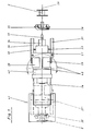
- FIG. 1 shows a plan view of the replaceable head 27 of the machine, which is the most important part.
- the Exchangeable head 27 works together with a spool magazine 22 (FIG. 2) by taking full spools 2 from it and after a pneumatically effected rotation about a vertical axis of rotation 40 of the exchangeable head 27 with its longitudinal axis 39 in the axis of the gripper (bobbin case carrier)
- the sewing machine swings in and the full bobbin 2 with the bobbin case carrier lower part 35 is inserted.
- the interchangeable head 27 can be moved out laterally on a carriage 26, ie it can be moved away from the sewing machine in the axial direction 39.
- the interchangeable head 27 has a receptacle 34 for the bobbin case carrier 35.
- a resilient shaft extension 37 is arranged in this receptacle 34.
- connection for example a pawl 38
- the connection is released between the two parts of which the bobbin case carrier usually consists, so that the bobbin case carrier lower part 35 with the bobbin 2 can be removed from the sewing machine.
- the interchangeable head 27 is arranged to be tiltable about a horizontal axis 41.
- a second interchangeable head 27 ′ can be arranged on the slide 26 in the longitudinal axis 39 or at an angle to it, which makes it possible to swivel the first interchangeable head 27 with an empty bobbin 2 in the bobbin case carrier lower part 35 and a further bobbin case carrier lower part 35 'with a full spool 2'.
- the interchangeable head 27 can be rotated further about its longitudinal axis 39 by means of a pneumatic adjusting cylinder 42 in order to be able to thread the thread of the bobbin 2 into the lower part 35 of the bobbin case carrier.
- FIG. 2 shows a schematic representation of additional facilities on the magazine.
- the exchangeable head 27 transfers the empty spool 2 to a magazine rod 57, whereupon the exchangeable head 27 swivels to the side 58 of the magazine 22 for full spools 2 in order to grip a full spool.
- a suction nozzle 61 is attached to the side of this magazine 22 and sucks in the thread hanging out of the slot 59.
- a pair of pliers 62 is provided which can be actuated pneumatically and tensions the thread in such a way that the thread is automatically threaded when the interchangeable head 27 is pivoted through 90 °.
- the pneumatic pliers 62 then perform a movement to release the thread, whereupon the interchangeable head 27 inserts the full bobbin 2 into the sewing machine after a 90 ° swivel.
Landscapes
- Engineering & Computer Science (AREA)
- Textile Engineering (AREA)
- Sewing Machines And Sewing (AREA)
Abstract
Description
- Die Erfindung betrifft eine Maschine zum automatischen Auswechseln von Unterfadenspulen, insbesondere für Steppstichnähmaschinen, mit einer durch pneumatische Zylinder betätigbaren Vorrichtung zum Entnehmen einer leeren Spule aus einem Spulenkapsel-Unterteil der Nähmaschine, zum Entnehmen einer vollen Spule aus einem Magazin und zum Transferieren dieser vollen Spule in die Nähmaschine, wobei die pneumatischen Zylinder Schlitten betätigen, auf denen Greiferhebel bzw. ein Spulenträger sitzen, die damit quer verfahrbar sind.
- Im Zuge der Automatisierung von Nähanlagen sind Spulautomaten entwickelt worden, die ein selbstätiges Bewickeln von Unterfadenspulen an Nähmaschinen bewirken. Das automatische Bewickeln der Unterfadenspulen bedingt aber, um effektiv zu sein, auch einen automatischen Spulenwechsel.
- Einen solchen automatischen Spulenwechsler zeigt die US-PS 33 76 838. Dabei dient ein pneumatisch schwenkbarer und elektromagnetisch ausfahrbarer Greiferhebel zur Entnahme der Spule aus dem Spulenkapselträger der Nähmaschine, während ein schlittenförmiger Spulenträger pneumatisch zwischen dem Magazin und der Nähstation hin- und herfahrbar ist.
- Eine Steuereinrichtung überwacht das zeitgerechte Arbeiten der einzelnen Bauteile. Die Vorrichtung ist vergleichsweise sperrig und seitlich weit ausladend, so daß ihr Anbau an der Nähmaschine Schwierigkeiten bereitet.
Die US-PS 26 90 725 betrifft ebenfalls einen automatischen Spulenwechsler, bei dem eine hin- und hergehende Schaltwelle, die durch einen Pneumatik-Zylinder betätigt wird, an ihrem Ende einen Greiferklauenträger aufweist. Dieser ist um die Achse der Schaltwelle drehbar und mit Aufnahmevorrichtungen zum Erfassen der Spulen versehen. - Durch die Drehung des Greiferklauenträgers erfolgt das Transferieren der vollen bzw. leeren Spulen. Die Vorrichtung weist viele komplizierte Einselteile auf und ist aufwendig in der Herstellung.
- Der Erfindung liegt die Aufgabe zugrunde, eine Maschine zum automatischen Auswechseln von Unterfadenspulen zu schaffen, die in Verbindung mit einem Spulenaufwickelautomaten bei schnellaufenden Industrie-Nähmaschinen einsetzbar ist und sich durch hohe Zuverlässigkeit, kompakte Bauweise und einfachen Aufbau auszeichnet.
- Zur Lösung dieser Aufgabe dienen die im Anspruch 1 gekennzeichnet Merkmale. Die Unteransprüche enthalten zweckmäßige weite Ausbildungen.
Durch die erfindungsgemäße Maschine ist es möglich, auch bei schnellaufenden Industrie-Nähmaschinen ein selbsttätiges Auswechseln leerer Unterfadenspulsen gegen volle Spulen zu bewerkstelligen. - Ein Ausführungsbeispiel der erfindungsgemäßen Vorrichtung ist in den Zeichnungen dargestellt.
Es zeigen: - Fig. 1
- eine Ansicht des Wechselkopfes der Maschine in Draufsicht;
- Fig. 2
- eine schematische Ansicht von zusätzlichen Einrichtungen am Magazin.
- Figur 1 zeigt in Draufsicht den Wechselkopf 27 der Maschine, der den wesentlichsten Teil darstellt. Der Wechselkopf 27 arbeitet zusammen mit einem Spulen-Magazin 22 (Fig. 2), indem er daraus volle Spulen 2 entnimmt und nach einer pneumatisch bewirkten Drehung um eine senkrechte Drehachse 40 des Wechselkopfes 27 mit seiner Längsachse 39 in die Achse des Greifers (Spulenkapselträger) der Nähmaschine einschwenkt und die volle Spule 2 mit dem Spulenkapselträger-Unterteil 35 einsetzt. In gleicher Weise umgekehrt erfolgt dieser Vorgang bei der Entnahme einer leeren Spule aus der Nähmaschine. Der Wechselkopf 27 ist auf einem Schlitten 26 seitlich herausfahrbar, d.h. von der Nähmaschine in Achsrichtung 39 wegfahrbar. Er besteht aus zwei pneumatischen Zylindern 28, 29, die auf je einen zweiarmigen Greiferhebel 30, 31 wirken, wobei die Greiferhebel 30, 31 von Federn 32, 33 belastet sind, die das Öffnen der Greiferhebel 30, 31 bewirken, während die pneumatischen Zylinder 28, 29 zum Schließen der Greiferhebel 30, 31 dienen. Der Wechselkopf 27 hat eine Aufnahme 34 für den Spulenkapselträger 35. In dieser Aufnahme 34 ist ein federnder Wellenansatz 37 angeordnet. Durch entsprechende Betätigung der pneumatischen Zylinder 28,29 können die zweiarmigen Greiferhebel 30, 31 wahlweise einzeln oder auch gemeinsam betätigt werden. Bei Betätigung nur des rechten Greiferhebels 31 erfolgt die Lösung der Verbindung (z.B. einer Klinke 38) zwischen den beiden Teilen, aus denen der Spulenkapselträger üblicherweise besteht, so daß der Spulenkapselträger-Unterteil 35 mit der Spule 2 aus der Nähmaschine entnehmbar ist.
- Der Wechselkopf 27 ist um eine waagerechte Achse 41 kippbar angeordnet. Auf dem Schlitten 26 kann in der Längsachse 39 oder auch in einem Winkel dazu ein zweiter Wechselkopf 27' angeordnet sein, wodurch es möglich wird, beim Ausschwenken des ersten Wechselkopfes 27 mit einer leeren Spule 2 im Spulenkapselträger-Unterteil 35 einen weiteren Spulenkapselträger-Unterteil 35' mit einer vollen Spule 2' einzusetzen.
- Der Wechselkopf 27 ist weiter um seine Längsachse 39 mittels eines pneumatischen Stellzylinders 42 drehbar, um den Faden der Spule 2 in den Spulenkapselträger-Unterteil 35 einfädeln zu können.
- Figur 2 zeigt in schematischer Darstellung zusätzliche Einrichtungen am Magazin. Beim Schwenken um seine senkrechte Achse 40 übergibt der Wechselkopf 27 die leere Spule 2 an eine Magazinstange 57, worauf der Wechselkopf 27 zur Seite 58 des Magazins 22 für volle Spulen 2 schwenkt, um eine volle Spule zu greifen. Seitlich an diesem Magazin 22 ist eine Saugdüse 61 angebracht, die den aus dem Schlitz 59 heraushängenden Faden ansaugt. Zwischen dem Magazin 22 und der Saugdüse 61 ist eine Zange 62 vorgesehen, die pneumatisch zu betätigen ist und den Faden derart spannt, daß bei einem Schwenken des Wechselkopfes 27 um 90° der Faden selbsttätig eingefädelt wird. Die pneumatische Zange 62 führt darauf eine Bewegung zur Freigabe des Fadens aus, worauf der Wechselkopf 27 nach einer 90°-Schwenkung die volle Spule 2 in die Nähmaschine einsetzt.
Claims (10)
- Maschine zum automatischen Auswechseln von Unterfaden-Spulen für insbesondere Steppstichnähmaschinen mit einer durch pneumatische Zylinder betätigbaren Vorrichtung zum Entnehmen einer leeren Spulen aus einem Spulenkapsel-Unterteil der Nähmaschine, zum Entnehmen einer vollen Spule aus einem Magazin und zum Transferieren dieser vollen Spule in die Nähmaschine, wobei die pneumatischen Zylinder Schlitten betätigen, auf den Greiferhebel bzw. ein Spulenträger sitzen, die damit quer verfahrbar sind, dadurch gekennzeichnet, daß auf dem Schlitten (26) ein Wechselkopf (27) sitzt, der seitlich der Nähmaschine in Achsrichtung (39) herausfahrbar ist,
daß der Wechselkopf (27) in eine zur Achse des Greifers der Nähmaschine senkrechte Drehachse (40) auf dem Schlitten (26) in die Achsrichtung (39) einschenkbar ist, und
daß der Wechselkopf (27) eine Aufnahme (34) mit einem federnden Wellenansatz (37) für den Spulenkapselträger-Unterteil (35) und zwei zweiarmige Greiferhebel (30,31) aufweist, die mit dem Spulenkapselträger-Unterteil (35) zusammenwirken und von den pneumatischen Zylindern (28,29) betätigbar sind. - Maschine nach Anspruch 1, dadurch gekennzeichnet, daß die Greiferhebel (30,31) von Federn (32,33) belastet sind, die das Öffnen der Greiferhebel (30,31) bewirken, während das Schließen der Greiferhebel (30,31) über die pneumatischen Zylinder (28,29) erfolgt.
- Maschine nach Anspruch 1 oder 2, dadurch gekennzeichnet, daß die Greiferhebel (30,31) wahlweise einzeln oder gemeinsam betätigbar sind.
- Maschine nach einem der Ansprüche 1 bis 3, dadurch gekennzeichnet, daß der eine Greiferhebel (31) an seinem freien Ende mit einer Vorrichtung zum Lösen der in Gestalt einer Klinke (38) ausgeführten Verbindung der beiden Teile des Spulenkapselträgers (35) ausgestattet ist.
- Maschine nach einem der Ansprüche 1 bis 4, dadurch gekennzeichnet, daß die Drehung des Wechselkopfes (27) um die Drehachse (40) pneumatisch erfolgt.
- Maschine nach einem der Ansprüche 1 bis 5, dadurch gekennzeichnet, daß der Wechselkopf (27) um eine waagerechte Achse (41) kippbar ist.
- Maschine nach einem der Ansprüche 1 bis 6, dadurch gekennzeichnet, daß der Wechselkopf (27) um seine Längsachse (39) mittels eines pneumatischen Stellzylinders (42) drehbar ist, um den Faden der Spule (2) in den Spulenkapselträger-Unterteil (35) einfädeln zu können.
- Maschine nach einem der Ansprüche 1 bis 7, dadurch gekennzeichnet, daß auf dem Schlitten (26) in der Längsachse (39) oder in einem Winkel dazu ein zweiter Wechselkopf (27') angeordnet ist, wodurch es möglich wird, beim Ausschwenken des ersten Wechselkopfes (27) mit einer leeren Spule (2) im Spulenkapselträger-Unterteil (35) einen weiteren Spulenkapselträger-Unterteil (35') mit einer vollen Spule (2') bei der Drehung des Wechselkopfes (27) einzusetzen.
- Maschine nach einem der Ansprüche 1 bis 8, dadurch gekennzeichnet, daß der Wechselkopf (27) beim Schwenken um seine senkrechte Achse (40) die leere Spule (2) an eine Magazinstange (57) übergibt, worauf der Wechselkopf (27) zur Seite (58) des Magazins (22) für volle Spulen (2) schwenkt, um eine volle Spule (2) zu greifen.
- Maschine nach einem der Ansprüche 1 bis 9, dadurch gekennzeichnet,
daß am Magazin (22) eine Saugdüse (61) angebracht ist, die den aus dem Schlitz (59) heraushängenden Faden ansaugt,
daß eine pneumatisch betätigte Zange (62) den Faden derart spannt, daß bei einem Schwenken des Wechselkopfes (27) um 90° der Faden eingefädelt ist, und
daß die pneumatische Zange (62) eine Bewegung zur Freigabe des Fadens ausführt, worauf der Wechselkopf (27) die volle Spule (2) in die Nähmaschine einsetzt.
Priority Applications (1)
| Application Number | Priority Date | Filing Date | Title |
|---|---|---|---|
| AT90909625T ATE93285T1 (de) | 1989-06-22 | 1990-06-20 | Maschine zum automatischen auswechseln von unterfadenspulen fuer insbesondere steppstichnaehmaschinen. |
Applications Claiming Priority (4)
| Application Number | Priority Date | Filing Date | Title |
|---|---|---|---|
| DE3943467 | 1989-06-22 | ||
| DE3920461 | 1989-06-22 | ||
| DE3920461 | 1989-06-22 | ||
| DE3943467 | 1989-06-22 |
Publications (2)
| Publication Number | Publication Date |
|---|---|
| EP0479838A1 EP0479838A1 (de) | 1992-04-15 |
| EP0479838B1 true EP0479838B1 (de) | 1993-08-18 |
Family
ID=25882226
Family Applications (1)
| Application Number | Title | Priority Date | Filing Date |
|---|---|---|---|
| EP90909625A Expired - Lifetime EP0479838B1 (de) | 1989-06-22 | 1990-06-20 | Maschine zum automatischen auswechseln von unterfadenspulen für insbesondere steppstichnähmaschinen |
Country Status (6)
| Country | Link |
|---|---|
| EP (1) | EP0479838B1 (de) |
| AU (1) | AU5920290A (de) |
| BR (1) | BR9007444A (de) |
| DE (1) | DE59002404D1 (de) |
| ES (1) | ES2044600T3 (de) |
| WO (1) | WO1990015894A1 (de) |
Families Citing this family (3)
| Publication number | Priority date | Publication date | Assignee | Title |
|---|---|---|---|---|
| TW262494B (de) * | 1993-08-31 | 1995-11-11 | Zyuki Kk | |
| IT1274445B (it) * | 1995-05-08 | 1997-07-17 | Osvaldo Vezzoli | Comando per il cambio automatico della bobina del filo inferiore, per macchine da cucire |
| DE102016005166A1 (de) * | 2016-04-30 | 2017-11-02 | Pfaff Industriesysteme Und Maschinen Gmbh | Nähmaschine mit einer Spulenkapselwechseleinrichtung |
Family Cites Families (4)
| Publication number | Priority date | Publication date | Assignee | Title |
|---|---|---|---|---|
| US2438459A (en) * | 1945-06-16 | 1948-03-23 | Richard Walsh Mcgann | Sewing machine |
| US2733676A (en) * | 1951-08-09 | 1956-02-07 | Device for automatically exchanging | |
| US3376838A (en) * | 1966-02-01 | 1968-04-09 | Ivanhoe Res Corp | Bobbin changer for sewing machines |
| US3981256A (en) * | 1975-05-09 | 1976-09-21 | J. P. Stevens & Co., Inc. | Magnetic automatic bobbin changer for sewing machines |
-
1990
- 1990-06-20 ES ES90909625T patent/ES2044600T3/es not_active Expired - Lifetime
- 1990-06-20 BR BR909007444A patent/BR9007444A/pt not_active IP Right Cessation
- 1990-06-20 EP EP90909625A patent/EP0479838B1/de not_active Expired - Lifetime
- 1990-06-20 WO PCT/DE1990/000468 patent/WO1990015894A1/de not_active Ceased
- 1990-06-20 DE DE9090909625T patent/DE59002404D1/de not_active Expired - Fee Related
- 1990-06-20 AU AU59202/90A patent/AU5920290A/en not_active Abandoned
Also Published As
| Publication number | Publication date |
|---|---|
| WO1990015894A1 (de) | 1990-12-27 |
| EP0479838A1 (de) | 1992-04-15 |
| AU5920290A (en) | 1991-01-08 |
| ES2044600T3 (es) | 1994-01-01 |
| DE59002404D1 (de) | 1993-09-23 |
| BR9007444A (pt) | 1992-06-16 |
Similar Documents
| Publication | Publication Date | Title |
|---|---|---|
| DE3872476T2 (de) | Verfahren und vorrichtung zum abnehmen von garnspulen und zum ablegen dieser spulen in einen spulenwagen. | |
| DE3348031C2 (de) | ||
| DE4427178C2 (de) | Unterfaden-Zufuhrvorrichtung | |
| EP0374403A1 (de) | Einrichtung zum pneumatischen Erfassen und Überkopfabziehen des Fadenendes eines Kopses | |
| WO1993009052A1 (de) | Spulenwechselvorrichtung | |
| DE3811667A1 (de) | Verfahren und vorrichtung zum transportieren von fadenlieferspulen | |
| CH692111A5 (de) | Kreuzspulenwechseleinrichtung einer Kreuzspulen herstellenden Textilmaschine. | |
| DE9111159U1 (de) | Werkzeuggreifer | |
| DD299664A5 (de) | Betriebsverfahren und vorrichtung zum automatisierten auswechseln von auflaufspulen, insbesondere zwirnkreuzspulen, gegen leere aufwickelhuelsen | |
| DE69907789T2 (de) | Verfahren und Vorrichtung zum Zuführen von Rollen | |
| DE69822592T2 (de) | Aufwickelvorrichtung insbesondere für Garn | |
| DE3823473C2 (de) | ||
| DE4125107A1 (de) | Spulenhuelsenaufnahmevorrichtung | |
| DE19524946B4 (de) | Kreuzspulen herstellende Textilmaschine | |
| DD298010A5 (de) | Maschine zum automatischen auswechseln von unterfadenspulen fuer insbesondere steppstichnaehmaschinen | |
| DE3800186A1 (de) | Verfahren zur belieferung des bedienungswerkes einer textilmaschine mit leeren spulhuelsen, sowie vorrichtung zum durchfuehren dieses verfahrens | |
| EP0051222A1 (de) | Vorrichtung zum Einführen von Fäden und dergleichen in eine Spulvorrichtung | |
| WO1990015894A1 (de) | Maschine zum automatischen auswechseln von unterfadenspulen für insbesondere steppstichnähmaschinen | |
| DE69417181T2 (de) | Spulenaufsetz- und Abnehmvorrichtung für eine Textilwickelmaschine | |
| DE19534914A1 (de) | Aufspulmaschine zum Aufspulen mehrerer Fäden zu Spulen | |
| DE3321058C2 (de) | Vorrichtung zum Spulenwechsel an einer Aufwickelmaschine für grobe Garne | |
| DE4019963C2 (de) | ||
| DE4238548C2 (de) | Verfahren und Vorrichtung zur Handhabung von ringförmigen Spulen, Hülsen und dergleichen, insbesondere zum automatischen Spulenwechsel an Vorlagegattern von Textilmaschinen durch Zusammenwirken eines Spulenmanipulators mit aus den Gattern lösbaren Dornen | |
| DE3335063C2 (de) | Vorrichtung und Verfahren zur Bildung einer aus einer Abfallwicklung und einer Reservewicklung bestehenden Fadenreserve in einer Spulmaschine zum Aufspulen eines Fadens auf eine Spulhülse | |
| DE4119827C2 (de) | Fahrbare Spulenwechselvorrichtung an einer Vielstellen-Spulmaschine |
Legal Events
| Date | Code | Title | Description |
|---|---|---|---|
| PUAI | Public reference made under article 153(3) epc to a published international application that has entered the european phase |
Free format text: ORIGINAL CODE: 0009012 |
|
| 17P | Request for examination filed |
Effective date: 19911030 |
|
| AK | Designated contracting states |
Kind code of ref document: A1 Designated state(s): AT BE CH DE DK ES FR GB IT LI LU NL SE |
|
| 17Q | First examination report despatched |
Effective date: 19921203 |
|
| GRAA | (expected) grant |
Free format text: ORIGINAL CODE: 0009210 |
|
| AK | Designated contracting states |
Kind code of ref document: B1 Designated state(s): AT BE CH DE DK ES FR GB IT LI LU NL SE |
|
| PG25 | Lapsed in a contracting state [announced via postgrant information from national office to epo] |
Ref country code: NL Effective date: 19930818 Ref country code: DK Effective date: 19930818 Ref country code: BE Effective date: 19930818 |
|
| REF | Corresponds to: |
Ref document number: 93285 Country of ref document: AT Date of ref document: 19930915 Kind code of ref document: T |
|
| ET | Fr: translation filed | ||
| GBT | Gb: translation of ep patent filed (gb section 77(6)(a)/1977) |
Effective date: 19930817 |
|
| REF | Corresponds to: |
Ref document number: 59002404 Country of ref document: DE Date of ref document: 19930923 |
|
| ITF | It: translation for a ep patent filed | ||
| REG | Reference to a national code |
Ref country code: ES Ref legal event code: FG2A Ref document number: 2044600 Country of ref document: ES Kind code of ref document: T3 |
|
| NLV1 | Nl: lapsed or annulled due to failure to fulfill the requirements of art. 29p and 29m of the patents act | ||
| PLBE | No opposition filed within time limit |
Free format text: ORIGINAL CODE: 0009261 |
|
| STAA | Information on the status of an ep patent application or granted ep patent |
Free format text: STATUS: NO OPPOSITION FILED WITHIN TIME LIMIT |
|
| PG25 | Lapsed in a contracting state [announced via postgrant information from national office to epo] |
Ref country code: LU Free format text: LAPSE BECAUSE OF NON-PAYMENT OF DUE FEES Effective date: 19940630 |
|
| 26N | No opposition filed | ||
| EAL | Se: european patent in force in sweden |
Ref document number: 90909625.7 |
|
| REG | Reference to a national code |
Ref country code: CH Ref legal event code: PUE Owner name: CARL SCHMALE GMBH & CO. TRANSFER- SCHMALE-HOLDING Ref country code: CH Ref legal event code: PFA Free format text: CARL SCHMALE GMBH & CO. KG TRANSFER- CARL SCHMALE GMBH & CO. |
|
| REG | Reference to a national code |
Ref country code: FR Ref legal event code: TP |
|
| REG | Reference to a national code |
Ref country code: ES Ref legal event code: PC2A |
|
| REG | Reference to a national code |
Ref country code: GB Ref legal event code: IF02 |
|
| PGFP | Annual fee paid to national office [announced via postgrant information from national office to epo] |
Ref country code: FR Payment date: 20020528 Year of fee payment: 13 |
|
| PGFP | Annual fee paid to national office [announced via postgrant information from national office to epo] |
Ref country code: SE Payment date: 20020607 Year of fee payment: 13 |
|
| PGFP | Annual fee paid to national office [announced via postgrant information from national office to epo] |
Ref country code: ES Payment date: 20020612 Year of fee payment: 13 |
|
| PGFP | Annual fee paid to national office [announced via postgrant information from national office to epo] |
Ref country code: GB Payment date: 20020617 Year of fee payment: 13 |
|
| PGFP | Annual fee paid to national office [announced via postgrant information from national office to epo] |
Ref country code: DE Payment date: 20020625 Year of fee payment: 13 |
|
| PGFP | Annual fee paid to national office [announced via postgrant information from national office to epo] |
Ref country code: AT Payment date: 20020628 Year of fee payment: 13 |
|
| PGFP | Annual fee paid to national office [announced via postgrant information from national office to epo] |
Ref country code: CH Payment date: 20020913 Year of fee payment: 13 |
|
| PG25 | Lapsed in a contracting state [announced via postgrant information from national office to epo] |
Ref country code: GB Free format text: LAPSE BECAUSE OF NON-PAYMENT OF DUE FEES Effective date: 20030620 Ref country code: AT Free format text: LAPSE BECAUSE OF NON-PAYMENT OF DUE FEES Effective date: 20030620 |
|
| PG25 | Lapsed in a contracting state [announced via postgrant information from national office to epo] |
Ref country code: SE Free format text: LAPSE BECAUSE OF NON-PAYMENT OF DUE FEES Effective date: 20030621 Ref country code: ES Free format text: LAPSE BECAUSE OF NON-PAYMENT OF DUE FEES Effective date: 20030621 |
|
| PG25 | Lapsed in a contracting state [announced via postgrant information from national office to epo] |
Ref country code: LI Free format text: LAPSE BECAUSE OF NON-PAYMENT OF DUE FEES Effective date: 20030630 Ref country code: CH Free format text: LAPSE BECAUSE OF NON-PAYMENT OF DUE FEES Effective date: 20030630 |
|
| PG25 | Lapsed in a contracting state [announced via postgrant information from national office to epo] |
Ref country code: DE Free format text: LAPSE BECAUSE OF NON-PAYMENT OF DUE FEES Effective date: 20040101 |
|
| EUG | Se: european patent has lapsed | ||
| GBPC | Gb: european patent ceased through non-payment of renewal fee |
Effective date: 20030620 |
|
| REG | Reference to a national code |
Ref country code: CH Ref legal event code: PL |
|
| PG25 | Lapsed in a contracting state [announced via postgrant information from national office to epo] |
Ref country code: FR Free format text: LAPSE BECAUSE OF NON-PAYMENT OF DUE FEES Effective date: 20040227 |
|
| REG | Reference to a national code |
Ref country code: FR Ref legal event code: ST |
|
| REG | Reference to a national code |
Ref country code: ES Ref legal event code: FD2A Effective date: 20030621 |
|
| PG25 | Lapsed in a contracting state [announced via postgrant information from national office to epo] |
Ref country code: IT Free format text: LAPSE BECAUSE OF NON-PAYMENT OF DUE FEES;WARNING: LAPSES OF ITALIAN PATENTS WITH EFFECTIVE DATE BEFORE 2007 MAY HAVE OCCURRED AT ANY TIME BEFORE 2007. THE CORRECT EFFECTIVE DATE MAY BE DIFFERENT FROM THE ONE RECORDED. Effective date: 20050620 |