EP0479720A1 - Method and device to lay false floors as well as false floor supports - Google Patents
Method and device to lay false floors as well as false floor supports Download PDFInfo
- Publication number
- EP0479720A1 EP0479720A1 EP91810744A EP91810744A EP0479720A1 EP 0479720 A1 EP0479720 A1 EP 0479720A1 EP 91810744 A EP91810744 A EP 91810744A EP 91810744 A EP91810744 A EP 91810744A EP 0479720 A1 EP0479720 A1 EP 0479720A1
- Authority
- EP
- European Patent Office
- Prior art keywords
- supports
- support
- floor
- height
- foot
- Prior art date
- Legal status (The legal status is an assumption and is not a legal conclusion. Google has not performed a legal analysis and makes no representation as to the accuracy of the status listed.)
- Granted
Links
Images


Classifications
-
- E—FIXED CONSTRUCTIONS
- E04—BUILDING
- E04F—FINISHING WORK ON BUILDINGS, e.g. STAIRS, FLOORS
- E04F15/00—Flooring
- E04F15/02—Flooring or floor layers composed of a number of similar elements
- E04F15/024—Sectional false floors, e.g. computer floors
-
- E—FIXED CONSTRUCTIONS
- E04—BUILDING
- E04F—FINISHING WORK ON BUILDINGS, e.g. STAIRS, FLOORS
- E04F15/00—Flooring
- E04F15/02—Flooring or floor layers composed of a number of similar elements
- E04F15/024—Sectional false floors, e.g. computer floors
- E04F15/02447—Supporting structures
- E04F15/02464—Height adjustable elements for supporting the panels or a panel-supporting framework
- E04F15/0247—Screw jacks
- E04F15/02476—Screw jacks height-adjustable from the upper side of the floor
-
- E—FIXED CONSTRUCTIONS
- E04—BUILDING
- E04F—FINISHING WORK ON BUILDINGS, e.g. STAIRS, FLOORS
- E04F15/00—Flooring
- E04F15/02—Flooring or floor layers composed of a number of similar elements
- E04F15/024—Sectional false floors, e.g. computer floors
- E04F15/02447—Supporting structures
- E04F15/02464—Height adjustable elements for supporting the panels or a panel-supporting framework
- E04F15/02488—Height adjustable elements for supporting the panels or a panel-supporting framework filled with material hardening after application
-
- E—FIXED CONSTRUCTIONS
- E04—BUILDING
- E04F—FINISHING WORK ON BUILDINGS, e.g. STAIRS, FLOORS
- E04F21/00—Implements for finishing work on buildings
- E04F21/20—Implements for finishing work on buildings for laying flooring
Definitions
- Raised floors (also called “raised floors”) essentially consist of floor plates lined up next to each other and these supporting, height-adjustable supports, which, arranged in a regular grid, rest on a bare floor (bare ceiling).
- Such raised floors are mainly used in office, administrative, industrial and commercial buildings, etc., in order to be able to lay a wide variety of lines in the cavity under the floor slabs on the unfinished floor (electrical power supply lines, control and data lines, pipes for ventilation, heating, Sewage, etc.). Thanks to easy access after lifting off individual floor slabs, such installations can be changed at any time and adapted to changing needs.
- each support is individually measured, offset and adjusted in height at a grid point on the bare floor; Despite unevenness in the floor, each support must stand exactly perpendicular to the grid point, for which purpose the support foot is lined with wedges or supports with joint arrangements are used.
- the supports have screw threads throughout for height adjustment.
- the adjustment is usually carried out by placing a floor slab over adjacent, already placed and the new pillar and then checking the plate position using a spirit level; it is often necessary to remove and replace the heavy plates. So far, the double floor installation has been very tedious due to the heavy physical work close to the floor and only progresses slowly even with trained personnel.
- the aim of the present invention is to considerably accelerate the progress of work compared to previously and to make the work considerably easier in order to avoid severe fatigue, back and joint damage etc.
- the horizontal auxiliary plane can be identical to the support plane of the floor slabs or can be parallel to this. It can e.g. are slightly lower, in which case the set and adjusted supports are supplemented by an additional, uniform support part before the base plates are placed on the head part.
- the invention further relates to a device for performing the aforementioned method according to the invention.
- This device is characterized by a frame which defines the auxiliary level above the field and which has height-adjustable support members for positioning the device and releasable holding means for the head parts of the supports to be introduced in the field, around the head parts at points on the frame corresponding to the grid points, aligned with the height of the auxiliary level and protruding vertically from it temporarily.
- This device enables the supports to be introduced and set in groups, their vertical position and alignment with the grid points being given to the whole group after the auxiliary level or the frame has been leveled.
- the invention relates to a prefabricated raised floor support, which is particularly developed and suitable for use in the aforementioned method and with the aforementioned device (although it can also be used elsewhere). It is assumed that there is a raised floor support with a head section and foot section, which are adjustable relative to each other for the purpose of adjusting the height of the support. According to the invention, such a support is characterized in that the head part and the foot part are guided loosely with respect to one another and are continuously displaceable in the direction of the support axis without mutual rotation, and in that locking means are provided for mutually fixing the relative position between the head part and the foot part.
- the raised floor support according to the invention designed in this way (in contrast to known supports with thread adjustment) makes it possible to adjust the height of several supports at the same time - and also simultaneously with the Leveling the auxiliary level - to be carried out.
- a device which is intended to compensate for unevenness in the raw floor before the double floor installation.
- the device can be moved on the bare floor and has lateral holding devices for semi-finished material strands. These strands are individually lowered to grid points on the bare floor, glued there and, after the adhesive has set, cut to a defined height using a circular saw. In this way, base elements with a defined level are formed on the bare floor. Only after such preparation and without further use of the device are the actual supports - in one piece and of uniform height - placed on the base elements. Again, they must be connected to the bases before the panels can be placed on the supports.
- prefabricated supports consisting of a head part and foot part are introduced into the device, placed on the grid points, adjusted in height and fixed.
- the supports are specially designed for this method and the device. This significantly speeds up and facilitates the work.
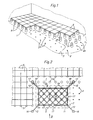
- the double floor shown in FIG. 1 during the laying and partly already laid has supports 5 arranged in a regular grid and resting on the unfinished floor 1.
- These carry floor plates 6 lined up next to each other, the contacting corners of four plates each resting on a support 5.
- Usually square plates are e.g. 60 cm edge length used, but other formats are also possible; the grid in which the supports 5 are arranged is of course given by the plate format.
- Grid points on the bare floor 1 that are not yet occupied are designated by 2.
- additional supports can be placed within the grid squares on grid positions 2a, e.g. to support the plates 6 in the middle when there is a high floor load.
- the supports 5 Since the unfinished floor 1 is usually fraught with level inaccuracies and uneven, the supports 5 must be adjustable in height or adjustable in length. In addition, each support must stand with its longitudinal axis vertically and precisely on the grid point, even if the support is uneven. Both of the aforementioned conditions must be met so that the base plates 6 carried by the supports 5 form a horizontal, flat base surface at the desired height.
- the supports 5 are shown in a highly simplified manner with the head part 7 and foot part 8, which are adjustable relative to one another for the purpose of height adjustment of the supports.
- the supports 5 can be connected to one another at their upper ends by horizontal struts (not shown) which run along the sides of the plate and / or diagonally to the plates.
- Intermediate layers (not shown), on which the plates 6 come to rest, can also be provided on the head part 7 of each support after the supports have been set and adjusted.
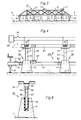
- an auxiliary level 4 (FIG. 3 ) leveled at a distance above the bare floor 1 (the field 3 can only comprise one row or, as shown, several rows of grid points 2).
- the height of the horizontal auxiliary plane 4 is of course related to the target position of the base plates 6, ie the position of the auxiliary plane can be identical to the underside of the plates 6 or else deviate, if, as mentioned above, on the supports 5 after their height adjustment Liner is put on.
- leveled auxiliary level 4 are then set and fixed on the grid points 2 within the field 3, the prefabricated supports 5 to the respective height corresponding to the (different) distance between the (uneven) raw floor 1 and the auxiliary level 4.
- the base plates 6 are finally laid on the supports set and set in this way. The latter can either take place "field by field” immediately or later over a larger, contiguous floor area.
- the device 10 has a frame 11, which is preferably designed as a torsion-resistant and bending-resistant lattice structure and which defines the auxiliary level 4. Height-adjustable support members 16, 16 'serve to position and level the device 10 above the field 3 in the manner described below. Furthermore, the device 10 has releasable holding means 15 (which are not shown in the present example) for the head parts 7 of the supports 5.
- the holding means serve to temporarily fix the supports 5 - at least their head part 7 - at locations on the frame 11 which correspond to the grid points 2, in such a way that the head parts 7 are aligned with the level of the auxiliary plane 4 and perpendicularly from it stand out.
- the device 10 has four arms 12 projecting laterally from the rectangular frame 11.
- the arms 12 are either set up to align the frame with adjacent supports 5 that have already been placed (top in FIG. 2), or they are provided with height-adjustable support feet 16 (bottom in FIG. 2).
- the support feet 16 are preferably fastened removably;
- the ends of the cantilevers 12 (without support feet 16 ′) lie on the supports that have already been placed, the height of the latter is thus “removed” by the device 10.
- the outriggers 12 can, as indicated, be provided with sleeves 13 or the like, which grip over the supports 5 serving as a reference.
- the device 10 or the auxiliary level 4 is then leveled by adjusting the height of the support feet 16 on the other arms 12.
- the device 10 can be provided with leveling elements 17 for this purpose.
- the process can be carried out by manually adjusting the support feet (e.g. by means of a threaded spindle) and simultaneously observing the leveling members 17, but it can also be automated, for example using electronic leveling means and e.g. Support feet adjustable pneumatically or by means of a thread and stepper motor drive 16.
- auxiliary level When leveling, it is by no means necessary that supports that have already been set and used serve as a reference, rather the auxiliary level can also be leveled by means of a reference system spanning the entire floor area of the room (for example optically using a laser beam ). Additional support feet 16 'are of course used above all at the beginning of work in a room if no reference supports 5 are available yet. Retractable and extendable wheels, castors or the like can also be provided for convenient handling and change of location of the device 10.
- a device 10 is particularly advantageous because a plurality of supports 5 (or at least their head part) are positioned jointly or simultaneously on the grid points 2 within the relevant field 3 and kept perpendicular.
- a plurality of supports 5 or at least their head part
- the height adjustment of the supports introduced in this way If the leveling takes place by approaching the auxiliary level 4 to the bare floor 1 (lowering the device from above), the height adjustment can be achieved to a certain extent automatically and at the same time as the leveling by shortening the supports introduced.
- "telescopically" adjustable supports as are described below, for example, are particularly useful.
- the supports introduced after the leveling of the auxiliary level 4 can be accomplished by extending the (previously briefly set) supports starting from the auxiliary level 4.
- both conventional, thread-adjustable and telescopically adjustable supports are suitable for this type of adjustment, although the latter can be set more quickly and conveniently.
- the foot part 8 of each support that comes to rest on the bare floor 1 must be fastened there. This can be done in a manner known per se, in particular by gluing.
- the above-mentioned holding means 15 for the head part of the supports 5 on the device 10 are located at points 2 '(FIG. 3) which correspond to the grid points 2 of the field 3.
- the holding means should be such that after the setting, setting and fixing of the supports 5 they release them so that the device 10 can be lifted off and positioned over a next field 3.
- the supports can be attached to the device e.g. be mechanically, electromagnetically, pneumatically, etc. releasably held.
- first at least three supports 5 are placed in the edge region of a field 3, and the height can be adjusted and fixed in order to thereby determine the auxiliary level 4;
- the remaining supports 5 of the field 3 are then introduced, onto which the already level set and fixed auxiliary level.
- This procedure corresponds to the use of two different (not shown) device parts in succession, namely a "measuring frame”, which only serves to set and adjust the first supports and thus to determine the auxiliary level, and a "mounting frame”, which then introduces the further supports , but is not set up for leveling, but focuses on the first mentioned supports.
- the device 10A has a lower part 61 and an upper part 65, both of which are designed as grid-like frames.
- the lower part 61 can be aligned and leveled in the manner described, e.g. by means of support feet 16 and dragonflies 17 or the like. It has stops 62 for the foot parts 51 of supports 50, such that the foot parts 51 come to rest on the raw floor 1 via the grid points 2 when the lower part 61 is aligned laterally.
- the upper part 65 can be placed on the lower part by means of legs 66 (only one shown) which fit in the centerings 63 on the lower part.
- the underside of the upper part 65 determines - with the lower part 61 leveled - the auxiliary level 4.
- electromagnets 67 are shown schematically, which are fed from a current source 68 and release all head parts simultaneously when a switch 69 is opened.
- the device 10A works as follows: First, the lower part 61 is positioned laterally and leveled to the desired height. Then the column base parts 51 are placed on grid points 2 with the aid of the stops 62 and fixed to the bare floor, e.g. stuck.
- the upper part 65 - preferably still separate from the lower part - is fitted with the support head parts and then placed on the lower part 61.
- the shaft 53 of an upper part engages with play in a bore 52 (FIG. 9) of the associated column foot part 51. All columns then have their desired height corresponding to the distance between the auxiliary level 4 and the raw floor 1.
- the game mentioned makes it possible for the foot part to be crooked according to the unevenness of the unfinished floor 1.
- Double floor supports which are particularly suitable and designed for use with the described method and the device 10 used are shown as exemplary embodiments in FIGS. 5 to 11.
- Such prefabricated supports each have a head part and a foot part, which are adjustable relative to one another for the purpose of height adjustment of the support.
- the supports shown here are characterized in that their head part and foot part are guided loosely in relation to each other and can be moved continuously in the direction of the support axis without mutual rotation. Locking means are also provided on these supports in order to mutually fix the relative position between the head part and the foot part.
- the head part 21 consists essentially of a tube section.
- the foot part is formed by a plurality of rods 30 arranged in parallel around the support axis 29; in the present case there are six bars 30, as a minimum three such bars are required.
- the head part 21 has a fixed ring 22 and a lower guide ring 23 on the inner tube wall. In both rings, half bores corresponding to the diameter of the rods 30 are provided, in which the rods are individually guided so as to be longitudinally movable along the tube wall.
- At the level of the ring 22 and radially inside the rods 30 there is a ring of six clamping jaws 24, each of which has a supplementary half-bore for each rod.
- the six clamping jaws 24 are held together loosely, for example by means of a resilient wire ring 25, and are therefore radially movable.
- the inside of the clamping jaws 24 forms a uniform conical surface with which the corresponding conical outer surface of a clamping block 26 interacts.
- the shaft of an axially arranged clamping screw 28 sits in a threaded bore of the clamping block 26, the head of which rests on a web 27 which is welded diametrically into the pipe section 21.
- the clamping jaws 24 and the clamping block 26 together form a wedge clamping device arranged centrally in the head part 21, which acts radially on all rods 30 and can be actuated from above by means of the clamping screw 28: in a lower position of the clamping block 26 (on the right in FIG. 5) the clamping jaws 24 are loosened and the rods 30 are longitudinally displaceable, on the other hand, when the screw 28 is tightened and the clamping block 26 is raised (left in FIG. 5), all the rods 30 are clamped.
- the wedge clamping device described above can also be designed to be self-reinforcing under load (self-locking) by reversing the conical direction of the conical sliding surfaces (narrowing cone downwards) and then tightening the clamping block against a web 27 located below (not shown).
- the rods 30 of the column foot part are spherical at their foot end. Every staff is with one
- the support plate 32, 33 is connected in an articulated manner by the spherical end being snapped into a corresponding cavity in the upper part 32 of the support plate, which is made of stretchable plastic.
- the lower part of each support plate is formed by a metal plate 33.
- the plastic upper parts 32 can preferably be movably connected to one another to form a ring, as can be seen in FIG. 6, right half.
- the base part of the support designed in this way can adapt to the slanted or uneven raw floor 1 when the support is adjusted, and a secure, non-positive support support is ensured with the support axis 29 standing vertically.
- the support surface of the column foot part (underside of the plates 33) is preferably glued to the bare floor, it being possible, for example, to use a double-sided adhesive film or an adhesive to be applied.
- the head part 41 and the foot part 43 are essentially designed as tube sections with the same diameter.
- Each tube section has regularly distributed, alternating longitudinal cutouts 42 'or 44' and longitudinal tabs 42 or 44 of the same width on the circumference.
- the lobes of one part each engage in the cutouts of the other part, as a result of which the head part 41 and foot part 43 are in turn telescopically guided together.
- the interlocking areas of both parts are encompassed by a clamping bracket 46 with a clamping screw 47. After the height of the support has been adjusted, the two parts are firmly clamped together by tightening the clamp.
- the safety or resilience can be increased by attaching fine ribs and grooves on the outside of the tabs 42 and 44 in the circumferential direction and on the inside of the clamping bracket 46 (not shown).
- the pipe section 43 of the foot part preferably rests on a dome-shaped foot plate 45, as a result of which oblique positions of the raw floor are compensated for.
- Both described "telescopic supports" 20 and 40 are very useful when used with the method described above. They can be conveniently adjusted in height (lengthening or shortening) without turning a thread and then fixed without any play.
- the design also ensures a favorable, direct flow of force when transferring the floor load from the overlying floor slabs to the unfinished floor, if you consider that the loaded floor slabs mainly due to (slight) deflection in the edge area, i.e. rest on the upper outer edge of the pipe sections 21 and 41. Since the force flow is essentially vertical downwards, there is practically no bending stress on the supports.
- the foot part 51 is designed as a cast part made of concrete or the like.
- the head part consists essentially of a threaded shaft 53 and a head plate 54.
- a threaded sleeve 55 is riveted to the latter, into which the shaft 53 is screwed and secured by means of a lock nut.
- the height adjustment of the support 50 is carried out in a device 10 or 10A by changing the "immersion depth" of the shaft 53 in the bore 52 of the foot part with the lock nut 56 tightened (not, for example - which must be emphasized here - by adjusting the Thread engagement of the shaft 53 in the sleeve 55).
- the axis 59 of the head part is perpendicular to the auxiliary plane 4, and the foot part can adapt to an inclination of the bare floor 1, which is possible due to the play between the shaft and the bore.
- the resulting relative position between the head part and foot part in the device is then fixed by the adhesive 58.
- the further embodiment variant of a raised floor support 70 according to FIG. 10 is again particularly designed for use in the method according to the invention and with a device 10 (or 10A), but can also be used without such a device.
- the double floor support shown in FIG. 10 has a head part 71 and a foot part 73, these two parts being adjustable relative to one another for the purpose of height adjustment of the support.
- the head part 71 consists essentially of a tube provided with an external thread 77, to which a head plate 72 can be welded.
- the tube of the head part 71 is guided telescopically on a tube 75 of the foot part and is displaceable in the direction of the support axis 79.
- a foot plate 80 is articulated below, which will be discussed in more detail below.
- a compression spring 74 is clamped between the head part 71 and the foot part 73, in that it is supported at the bottom, for example, against a pin 87 and at the top against the head plate 72.
- the effect of the spring 74 is such that when the support is unloaded, its parts 71, 73 are "pushed apart" by the compression spring, that is to say that the support has an excess height h o , as is indicated by dash-dotted lines in FIG. 10.
- Screw stop 76 adjustable in the form of a threaded ring. At the beginning of the column assembly or adjustment, this is in an upper position, which is also shown in broken lines in FIG. 10.
- the support is set to a desired height h s after it has been moved on the raw floor 1. This is done by pushing the parts 71 and 73 against each other against the force of the spring 74 in the direction of the arrow P until the desired height is reached.
- the illustrated support is held together with a group of further supports in a device 10 (10A) on the head part and projects vertically downward from the auxiliary plane determined by the device.
- the supports are then placed in groups on the bare floor 1 when leveling the device and, starting from the excess height h o , shortened to their respective desired height h s .
- each prop can also be individually adjusted to its target height.
- the screw stop 76 is screwed down on the thread 77 and placed against the foot part 73 in order to fix the set relative position between the head part and the foot part, so that the support can later take up the floor load .
- a flange 75a is preferably provided at the top of the pipe 75, against which the threaded ring 76 comes to rest. So that the support maintains its target height as long as it is not yet loaded (by later laying on the raised floor panels), it is advisable to provide locking means that act on the force between the parts 71 and 73 when the screw stop is engaged between this and the support foot part Spring 74 to overcome or hold. 10, several snap springs 78 are attached to the circumference of the stop ring 76 for this purpose. When the ring 76 is turned on, the springs 78 are bent outwards and slide over the flange 75a, in order then to engage behind the latter and to hold the ring 76 on the flange 75a.
- FIG. 11 A variant of such locking means is shown in FIG. 11: here, instead of snap springs 78, a plurality of permanent magnets 78 '(or also a closed, permanent magnetic ring) are attached to the underside of the threaded ring 76. When the stop is turned on, the ring 76 is then held magnetically on the flange, so that the support maintains its desired height despite the tensioned spring 74. With or without such locking means 78 or 78 ', it may be expedient to release the tension of the spring 74 when the desired height is set. This can e.g. just happen that the pin 87 is not stuck in the tube 75 and can be pulled out after adjustment, whereupon the spring relaxes.
- the special design of the base plate 80 according to FIG. 10 is such that a vertical position of the support or its axis 79 is ensured even when the plate is slanted on the floor 1 in any direction (indicated by dash-dotted lines in FIG. 10).
- Base plate 80 and telescopic tube 75 of base part 73 are held together by means of a screw 84 and anchor plate 86, an elastic intermediate layer 85 between the anchor plate and an inner flange of tube 75 permitting a limited inclination of base plate 80 with respect to axis 79 in any direction.
- Within a ring 81 on top of the plate 80 are several - e.g.
Abstract
Description
Doppelböden (auch "aufgeständerte Fussböden" genannt) bestehen im wesentlichen aus nebeneinandergereihten Bodenplatten und diese tragenden, höhenverstellbaren Stützen, die, in einem regelmässigen Raster angeordnet, auf einem Rohboden (Rohdecke) aufliegen. Solche Doppelböden werden vorwiegend in Büro-, Verwaltungs-, Industrie- und Gewerbebauten usw. vorgesehen, um im Hohlraum unter den Bodenplatten Leitungen verschiedenster Art frei auf dem Rohboden verlegen zu können (elektrische Stromversorgungsleitungen, Steuer- und Datenleitungen, Rohrleitungen für Lüftung, Heizung, Abwasser usw.). Dank leichtem Zugang nach Abheben einzelner Bodenplatten können solche Installationen jederzeit geändert und wechselnden Bedürfnissen angepasst werden.Raised floors (also called "raised floors") essentially consist of floor plates lined up next to each other and these supporting, height-adjustable supports, which, arranged in a regular grid, rest on a bare floor (bare ceiling). Such raised floors are mainly used in office, administrative, industrial and commercial buildings, etc., in order to be able to lay a wide variety of lines in the cavity under the floor slabs on the unfinished floor (electrical power supply lines, control and data lines, pipes for ventilation, heating, Sewage, etc.). Thanks to easy access after lifting off individual floor slabs, such installations can be changed at any time and adapted to changing needs.
Der Einbau bzw. das Verlegen der Doppelböden in herkömmlicher Weise ist allerdings recht mühsam und zeitraubend und wegen hoher Lohnkosten entsprechend teuer. Die Rohböden weisen infolge der Bautoleranzen erhebliche Niveau-Unterschiede und grössere oder kleinere Unebenheiten auf, die bei der Montage der Stützen ausgeglichen werden müssen, um eine genaue und horizontale Auflageebene in richtiger Höhe für die Bodenplatten zu bilden. Die herkömmliche Arbeitsweise ist so, dass jede Stütze einzeln auf eine Rasterstelle am Rohboden eingemessen, versetzt und in der Höhe eingestellt wird; trotz Bodenunebenheiten muss jede Stütze über der Rasterstelle genau lotrecht stehen, wozu der Stützenfuss mit Keilen unterlegt oder Stützen mit Gelenkanordnungen verwendet werden. Zur Höhenverstellung weisen die Stützen durchwegs Schraubgewinde auf. Das Einstellen erfolgt meist durch Auflegen einer Bodenplatte über benachbarte, bereits gesetzte sowie die neu zu setzende Stütze und anschliessendes Ueberprüfen der Plattenlage mittels Wasserwaage; dabei ist oft ein Wegnehmen und Wiederauflegen der schweren Platten erforderlich. Die Doppelboden-Montage ist also bisher infolge der schweren körperlichen Arbeit in Bodennähe sehr mühsam und schreitet auch mit geübtem Personal nur langsam voran.The installation or laying of the raised floors in a conventional manner is, however, quite tedious and time-consuming and, because of the high labor costs, correspondingly expensive. Due to the construction tolerances, the bare floors show considerable differences in level and larger or smaller bumps, which must be compensated for when installing the supports in order to form an exact and horizontal support level at the correct height for the floor slabs. The conventional way of working is that each support is individually measured, offset and adjusted in height at a grid point on the bare floor; Despite unevenness in the floor, each support must stand exactly perpendicular to the grid point, for which purpose the support foot is lined with wedges or supports with joint arrangements are used. The supports have screw threads throughout for height adjustment. The adjustment is usually carried out by placing a floor slab over adjacent, already placed and the new pillar and then checking the plate position using a spirit level; it is often necessary to remove and replace the heavy plates. So far, the double floor installation has been very tedious due to the heavy physical work close to the floor and only progresses slowly even with trained personnel.
Mit der vorliegenden Erfindung wird angestrebt, den Arbeitsfortschritt gegenüber bisher erheblich zu beschleunigen und dabei die Arbeiten wesentlich zu erleichtern, um starke Ermüdung, Rücken- und Gelenkschäden usw. zu vermeiden.The aim of the present invention is to considerably accelerate the progress of work compared to previously and to make the work considerably easier in order to avoid severe fatigue, back and joint damage etc.
Die Erfindung betrifft demnach ein Verfahren zum Verlegen von Doppelböden mit nebeneinandergereihten Bodenplatten und diese tragenden, höhenverstellbaren Stützen, wobei die Stützen, in einem regelmässigen Raster angeordnet, auf einem Rohboden aufliegen. Zur Erreichung der vorgenannten Ziele ist das Verfahren erfindungsgemäss dadurch gekennzeichnet,
- dass man jeweils über einem mehrere Rasterstellen umfassenden Feld eine Hilfsebene im Abstand über dem Rohboden nivelliert,
- dass man vorgefertigte, je aus Kopfteil und Fussteil bestehende Stützen auf den Rasterstellen zwischen Hilfsebene und Rohboden einbringt,
- dass man auf jeder Rasterstelle die Stützen entsprechend dem jeweiligen Bodenabstand der Hilfsebene auf Sollhöhe einstellt und Kopfteil und Fussteil aneinander fixiert,
- und dass man schliesslich die Bodenplatten auf die fixierten Stützen verlegt.
- that each auxiliary level is spaced above the bare floor over a field comprising several grid points,
- that prefabricated supports, each consisting of a headboard and footboard, are placed on the grid points between the auxiliary level and the unfinished floor,
- that the supports are set to the desired height at each grid point according to the respective floor clearance of the auxiliary level and the headboard and footboard are fixed to one another,
- and that you finally lay the floor slabs on the fixed supports.
Es werden also nicht mehr die Stützen einzeln vom unebenen Rohboden "aufbauend" eingestellt, sondern die Einstellung erfolgt ausgehend von der nivellierten, genauen Hilfsebene, welche jeweils für eine ganze Gruppe von Stützen die Bezugsebene für die (je nach Bodenunebenheit unterschiedliche) Stützenhöhe bildet. Die horizontale Hilfsebene kann mit der Auflageebene der Bodenplatten identisch sein oder zu dieser parallel liegen. Sie kann z.B. etwas tiefer liegen, in welchem Fall die gesetzten und eingestellten Stützen vor dem Auflegen der Bodenplatten am Kopfteil durch ein zusätzliches, einheitliches Auflageteil ergänzt werden.So the supports are no longer set individually from the uneven raw floor, but the setting is based on the leveled, precise auxiliary level, which forms the reference level for the support height for a whole group of supports (depending on the unevenness of the floor). The horizontal auxiliary plane can be identical to the support plane of the floor slabs or can be parallel to this. It can e.g. are slightly lower, in which case the set and adjusted supports are supplemented by an additional, uniform support part before the base plates are placed on the head part.
Die Erfindung bezieht sich ferner auf eine Vorrichtung zur Durchführung des vorgenannten, erfindungsgemässen Verfahrens. Diese Vorrichtung ist gekennzeichnet durch einen die Hilfsebene über dem Feld bestimmenden Rahmen, welcher höheneinstellbare Stützorgane zur Positionierung der Vorrichtung sowie lösbare Haltemittel fürdie Kopfteile derauf dem Feld einzubringenden Stützen aufweist, um die Kopfteile an den Rasterstellen entsprechenden Stellen des Rahmens, auf die Höhe der Hilfsebene ausgerichtet und von dieser senkrecht abstehend, vorübergehend zu fixieren. Diese Vorrichtung ermöglicht ein gruppenweises Einbringen und Setzen der Stützen, wobei deren vertikale Stellung und Ausrichtung auf die Rasterstellen nach dem Nivellieren der Hilfsebene bzw. des Rahmens bereits für die ganze Gruppe gegeben ist.The invention further relates to a device for performing the aforementioned method according to the invention. This device is characterized by a frame which defines the auxiliary level above the field and which has height-adjustable support members for positioning the device and releasable holding means for the head parts of the supports to be introduced in the field, around the head parts at points on the frame corresponding to the grid points, aligned with the height of the auxiliary level and protruding vertically from it temporarily. This device enables the supports to be introduced and set in groups, their vertical position and alignment with the grid points being given to the whole group after the auxiliary level or the frame has been leveled.
Schliesslich betrifft die Erfindung eine vorgefertigte Doppelbodenstütze, die zur Verwendung beim vorgenannten Verfahren und mit der vorgenannten Vorrichtung besonders entwickelt und geeignet (wiewohl auch anderweitig anwendbar) ist. Es wird dabei ausgegangen von einer Doppelbodenstütze mit Kopfteil und Fussteil, die zwecks Höheneinstellung der Stütze relativ zueinander verstellbar sind. Erfindungsgemäss ist eine solche Stütze dadurch gekennzeichnet, dass der Kopfteil und der Fussteil in bezug aufeinander lose geführt und in Richtung der Stützenachse ohne gegenseitige Drehung stufenlos verschiebbar sind, und dass Feststellmittel zur gegenseitigen Fixierung der Relativlage zwischen Kopfteil und Fussteil vorhanden sind. Die so gestaltete, erfindungsgemässe Doppelbodenstütze ermöglicht es (im Gegensatz zu bekannten Stützen mit Gewindeverstellung), die Höheneinstellung mehrerer Stützen gleichzeitig - und auch gleichzeitig einhergehend mit dem Nivellieren der Hilfsebene - vorzunehmen.Finally, the invention relates to a prefabricated raised floor support, which is particularly developed and suitable for use in the aforementioned method and with the aforementioned device (although it can also be used elsewhere). It is assumed that there is a raised floor support with a head section and foot section, which are adjustable relative to each other for the purpose of adjusting the height of the support. According to the invention, such a support is characterized in that the head part and the foot part are guided loosely with respect to one another and are continuously displaceable in the direction of the support axis without mutual rotation, and in that locking means are provided for mutually fixing the relative position between the head part and the foot part. The raised floor support according to the invention designed in this way (in contrast to known supports with thread adjustment) makes it possible to adjust the height of several supports at the same time - and also simultaneously with the Leveling the auxiliary level - to be carried out.
Aus der EP-A-0 077 070 ist eine Vorrichtung bekannt, die zum Ausgleichen von Unebenheiten des Rohbodens vor der Doppelboden-Montage bestimmt ist. Die Vorrichtung ist auf dem Rohboden verfahrbar und weist seitliche Halteeinrichtungen für Halbzeug-Materialstränge auf. Diese Stränge werden einzeln auf Rasterpunkte des Rohbodens abgesenkt, dort festgeklebt und, nach Abbinden des Klebers, auf definierter Höhe mittels einer Kreissäge abgetrennt. Auf diese Weise werden auf dem Rohboden Sockelelemente mit definiertem Niveau gebildet. Erst nach solcher Vorbereitung und ohne weitere Benutzung der Vorrichtung werden dann die eigentlichen Stützen - einteilig und von einheitlicher Höhe - auf die Sockelelemente gesetzt. Sie müssen wiederum mit den Sockeln verbunden werden, bevor die Platten auf die Stützen verlegt werden können.From EP-A-0 077 070 a device is known which is intended to compensate for unevenness in the raw floor before the double floor installation. The device can be moved on the bare floor and has lateral holding devices for semi-finished material strands. These strands are individually lowered to grid points on the bare floor, glued there and, after the adhesive has set, cut to a defined height using a circular saw. In this way, base elements with a defined level are formed on the bare floor. Only after such preparation and without further use of the device are the actual supports - in one piece and of uniform height - placed on the base elements. Again, they must be connected to the bases before the panels can be placed on the supports.
Im Gegensatz zur vorgenannten, bekannten Arbeitsweise werden nach der Erfindung direkt vorgefertigte Stützen, bestehend aus Kopfteil und Fussteil, in die Vorrichtung eingebracht, auf die Rasterstellen gesetzt, in der Höhe eingestellt und fixiert. Die Stützen sind für dieses Verfahren bzw. die Vorrichtung besonders gestaltet. Hierdurch wird die Arbeit wesentlich beschleunigt und erleichtert.In contrast to the aforementioned, known method of working, according to the invention, prefabricated supports consisting of a head part and foot part are introduced into the device, placed on the grid points, adjusted in height and fixed. The supports are specially designed for this method and the device. This significantly speeds up and facilitates the work.
Besondere und vorteilhafte Varianten des Verfahrens gemäss Anspruch 1, der Vorrichtung nach Anspruch 6 und der Doppelbodenstütze nach Anspruch 12 sind in den jeweiligen abhängigen Ansprüchen angegeben.Special and advantageous variants of the method according to
Nachstehend wird die Erfindung anhand von Ausführungsbeispielen und in Verbindung mit der Zeichnung näher erläutert.
- Fig. 1 zeigt perspektivisch und vereinfacht einen im Aufbau begriffenen Doppelboden,
- Fig. 2 zeigt eine ähnliche Situation wie Fig. 1 im Grundriss, mit einer beim Verlegen des Doppelbodens verwendeten Vorrichtung,
- Fig. 3 ist eine Ansicht in Richtung des Pfeiles 111 in Fig. 2 (bereits gesetzte Stützen und verlegte Bodenplatten sind weggelassen),
- Fig. 4 ist die Teildarstellung, teilweise im Vertikalschnitt, eines weiteren Ausführungsbeispiels einer Vorrichtung (in Verbindung mit Stützen nach Fig. 9),
- Fig. 5 zeigt ein erstes Ausführungsbeispiel einer geeigneten Doppelbodenstütze im Vertikalschnitt,
- Fig. 6 zeigt in der linken Hälfte eine Draufsicht auf die Stütze nach Fig. 5 und in der rechten Hälfte einen Schnitt entlang der Linie VI - VI in Fig. 5,
- Fig. 7 stellt ein weiteres Beispiel einer Stütze in Ansicht dar,
- Fig. 8 ist ein Schnitt entlang der Linie VIII - VIII in Fig. 7,
- Fig. 9 zeigt ein weiteres Ausführungsbeispiel einer Doppelbodenstütze in Ansicht (Fussteil geschnitten),
- Fig. 10 veranschaulicht noch eine weitere Ausführungsform einer Stütze im Vertikalschnitt, und
- Fig. 11 zeigt als Teildarstellung eine Variante zum Beispiel nach Fig. 10.
- 1 shows in perspective and simplified a double floor under construction,
- Fig. 2 shows a similar situation as Fig. 1 in plan, with a device used when laying the raised floor,
- Fig. 3 is a view in the direction of arrow 111 in Fig. 2 (already set supports and laid floor panels are omitted),
- 4 is the partial representation, partly in vertical section, of a further exemplary embodiment of a device (in connection with supports according to FIG. 9),
- 5 shows a first embodiment of a suitable raised floor support in vertical section,
- 6 shows in the left half a top view of the support according to FIG. 5 and in the right half a section along the line VI-VI in FIG. 5,
- 7 shows another example of a support in view,
- Fig. 8 is a section along the line VIII - VIII in Fig. 7,
- 9 shows a further embodiment of a raised floor support in view (foot section cut),
- 10 illustrates yet another embodiment of a support in vertical section, and
- 11 shows a partial representation of a variant, for example according to FIG. 10.
Der in Fig. 1 während des Verlegens dargestellte und teilweise bereits verlegte Doppelboden (z.B. von einer Wand eines Raumes ausgehend) weist in einem regelmässigen Raster angeordnete, auf dem Rohboden 1 aufliegende Stützen 5 auf. Diese tragen nebeneinandergereihte Bodenplatten 6, wobei jeweils die einander berührenden Ecken von vier Platten auf einer Stütze 5 aufliegen. Normalerweise werden quadratische Platten von z.B. 60 cm Kantenlänge verwendet, jedoch kommen auch andere Formate in Frage; der Raster, in welchem die Stützen 5 angeordnet sind, ist natürlich durch das Plattenformat gegeben. Noch unbesetzte Rasterstellen auf dem Rohboden 1 sind mit 2 bezeichnet. Wie rechts in Fig. 1 angedeutet, können innerhalb der Rasterquadrate auf Rasterstellen 2a zusätzliche Stützen gesetzt werden, um z.B. bei hoher Bodenbelastung die Platten 6 auch mittig zu unterstützen. Da der Rohboden 1 normalerweise mit Niveau-Ungenauigkeiten behaftet und uneben ist, müssen die Stützen 5 höhenverstellbar bzw. in ihrer Länge einstellbar sein. Zudem muss jede Stütze auch bei unebener Auflage mit ihrer Längsachse vertikal und genau auf der Rasterstelle stehen. Beide vorgenannten Bedingungen müssen erfüllt sein, damit die von den Stützen 5 getragenen Bodenplatten 6 eine horizontale, ebene Bodenfläche auf der gewünschten Höhe bilden.The double floor shown in FIG. 1 during the laying and partly already laid (e.g. starting from a wall of a room) has supports 5 arranged in a regular grid and resting on the
In den Fig. 1 bis 3 sind die Stützen 5 stark vereinfacht mit Kopfteil 7 und Fussteil 8 dargestellt, die zwecks Höheneinstellung der Stützen relativ zueinander verstellbar sind. In an sich bekannter Weise können die Stützen 5 untereinander an ihren oberen Enden durch (nicht dargestellte) Horizontalstreben verbunden sein, die entlang den Plattenseiten und/oderdiagonal zu den Platten verlaufen. Am Kopfteil 7 jeder Stütze können ferner nach dem Setzen und Einstellen der Stützen aufsetzbare Zwischenlagen (nicht dargestellt) vorgesehen sein, auf die die Platten 6 zu liegen kommen.1 to 3, the
Das Vorgehen beim erfindungsgemässen Verfahren und eine dabei verwendete Vorrichtung werden nun beispielsweise anhand der Fig. 2 und 3 erläutert: Uebereinem Feld 3, welches eine Mehrzahl von Rasterstellen 2 umfasst (siehe auch Fig. 1), wird jeweils eine Hilfsebene 4 (Fig. 3) im Abstand über dem Rohboden 1 nivelliert (das Feld 3 kann nur eine Reihe oder, wie dargestellt, mehrere Reihen von Rasterstellen 2 umfassen). Die Höhenlage der horizontalen Hilfsebene 4 steht natürlich in Beziehung mit der Sollage der Bodenplatten 6, d.h. die Lage der Hilfsebene kann mit der Unterseite der Platten 6 identisch sein oder aber davon abweichen, falls, wie oben erwähnt, auf die Stützen 5 nach deren Höheneinstellung eine Zwischenlage aufgesetzt wird. Bei gegebener, nivellierter Hilfsebene 4 werden sodann auf den Rasterstellen 2 innerhalb des Feldes 3 die vorgefertigten Stützen 5 auf die jeweilige Höhe entsprechend dem (unterschiedlichen) Abstand zwischen dem (unebenen) Rohboden 1 und der Hilfsebene 4 eingestellt und fixiert. Auf die so gesetzten und eingestellten Stützen werden schliesslich die Bodenplatten 6 verlegt. Letzteres kann entweder sogleich "Feld um Feld" oder später über eine grössere, zusammenhängende Bodenfläche erfolgen.The procedure in the method according to the invention and a device used in the process are now explained, for example, with reference to FIGS. 2 and 3: above an
Zur Durchführung des Verfahrens ist die Verwendung einer Vorrichtung zweckmässig, wie sie beispielsweise in den Fig. 2 und 3 dargestellt ist. Die Vorrichtung 10 weist einen vorzugsweise als verwindungs- und biegesteife Gitterkonstruktion ausgeführten Rahmen 11 auf, der die Hilfsebene 4 bestimmt. Höheneinstellbare Stützorgane 16, 16' dienen zur Positionierung und Nivellierung der Vorrichtung 10 über dem Feld 3 in weiter unten beschriebener Weise. Fernerweist die Vorrichtung 10 lösbare Haltemittel 15 (die beim vorliegenden Beispiel nicht näher dargestellt ) für die Kopfteile 7 der Stützen 5 auf. Die Haltemittel dienen dazu, die Stützen 5 - mindestens deren Kopfteil 7 - an Stellen des Rahmens 11, die den Rasterstellen 2 entsprechen, vorübergehend zu fixieren, und zwar so, dass die Kopfteile 7 auf die Höhe der Hilfsebene 4 ausgerichtet sind und von dieser senkrecht abstehen.To carry out the method, it is expedient to use a device such as that shown in FIGS. 2 and 3. The
Am dargestellten Beispiel weist die Vorrichtung 10 vier seitlich vom rechteckigen Rahmen 11 abstehende Ausleger 12 auf. Die Ausleger 12 sind entweder zur Ausrichtung des Rahmens auf bereits gesetzte, benachbarte Stützen 5 eingerichtet (oben in Fig. 2), oder sie sind mit höhenverstellbaren Stützfüssen 16 versehen (unten in Fig. 2). Im Hinblick auf verschiedene Anwendungsarten der Vorrichtung sind die Stützfüsse 16 vorzugsweise wegnehmbar befestigt; entsprechende Stützfüsse 16' können auch an den erwähnten Auslegern 12 vorgesehen sein, die zur Ausrichtung an benachbarten Stützen 5 (oben in Fig. 2) dienen. Im dargestellten Fall nach Fig. 2 liegen die Enden der genannten Ausleger 12 (ohne Stützfüsse 16') auf den bereits gesetzten Stützen auf, die Höhe der letzteren wird also von der Vorrichtung 10 "abgenommen". Zur seitlichen Positionierung der Vorrichtung 10 über dem mit Stützen zu belegenden Feld 3 können die Ausleger 12, wie angedeutet, mit Manschetten 13 o. dgl. versehen sein, welche über die als Referenz dienenden Stützen 5 greifen. Das Nivellieren der Vorrichtung 10 bzw. der Hilfsebene 4 wird dann durch Höhenverstellung der Stützfüsse 16 an den andern Auslegern 12 vorgenommen. Die Vorrichtung 10 kann zu diesem Zweck mit Nivellierorganen 17 versehen sein. Der Vorgang kann durch manuelles Einstellen der Stützfüsse (z.B. mittels Gewindespindel) und gleichzeitiges Beobachten der Nivellierorgane 17 erfolgen, er kann aber auch automatisiert werden, beispielsweise unter Verwendung elektronischer Nivelliermittel und z.B. pneumatisch oder mittels Gewinde und Schrittmotor-Antrieb verstellbaren Stützfüssen 16. Es ist beim Nivellieren keineswegs erforderlich, dass bereits gesetzte und eingestellte Stützen als Referenz dienen, vielmehr kann die Hilfsebene auch mittels eines die ganze Bodenfläche des Raumes überspannenden Referenzsystems nivelliert werden (beispielsweise optisch mittels Laserstrahl). Zusätzliche Stützfüsse 16' werden natürlich vor allem zu Beginn der Arbeit in einem Raum verwendet, wenn noch keine Referenzstützen 5 zur Verfügung stehen. Zur bequemen Handhabung und Ortsveränderung der Vorrichtung 10 können auch ein- und ausfahrbare Räder, Lenkrollen oder dergleichen vorgesehen sein.In the example shown, the
Die Verwendung einer Vorrichtung 10 ist vor allem deshalb vorteilhaft, weil damit eine Mehrzahl von Stützen 5 (oder mindestens deren Kopfteil) innerhalb des betreffenden Feldes 3 gemeinsam bzw. gleichzeitig auf die Rasterstellen 2 positioniert und lotrecht gehalten werden. Bezüglich Höheneinstellung der so eingebrachten Stützen bestehen verschiedene Möglichkeiten: Falls das Nivellieren durch Annäherung der Hilfsebene 4 an den Rohboden 1 erfolgt (Absenken der Vorrichtung von oben), kann man die Höheneinstellung gewissermassen selbsttätig und gleichzeitig mit dem Nivellieren durch Verkürzung der eingebrachten Stützen erreichen. Hierfür sind "teleskopartig" verstellbare Stützen, wie sie weiter unten beispielsweise beschrieben werden, besonders zweckmässig. Unabhängig von der Art des Nivellierens (Absenken oder Anheben der Vorrichtung 10) kann man aber auch die eingebrachten Stützen nach dem Nivellieren der Hilfsebene 4 durch Verlängern der (vorher kurz eingestellten) Stützen ausgehend von der Hilfsebene 4 bewerkstelligen. Für diese Einstellart eignen sich grundsätzlich sowohl herkömmliche, mittels Gewinde verstellbare wie auch teleskopartig verstellbare Stützen, wobei jedoch die letzteren rascher und bequemer einstellbar sind.The use of a
Der auf dem Rohboden 1 zur Auflage kommende Fussteil 8 jeder Stütze muss dort befestigt werden. Dies kann auf an sich bekannte Weise, insbesondere durch Verkleben erfolgen. Die weiter oben erwähnten Haltemittel 15 für den Kopfteil der Stützen 5 an der Vorrichtu ng 10 befinden sich an Stellen 2'(Fig. 3), die den Rasterstellen 2 des Feldes 3 entsprechen. Die Haltemittel sollen so beschaffen sein, dass sie nach dem Setzen, Einstellen und Fixieren der Stützen 5 diese freigeben, so dass die Vorrichtung 10 abgehoben und über einem nächsten Feld 3 positioniert werden kann. Die Stützen können an der Vorrichtung z.B. mechanisch, elektromagnetisch, pneumatisch usw. lösbar gehalten sein.The
Als weitere Verfahrensmöglichkeit ist zu erwähnen, dass man zuerst jeweils im Randbereich eines Feldes 3 mindestens drei Stützen 5 setzen, in der höhe einstellen und fixieren kann, um dadurch die Hilfsebene 4 zu bestimmen; anschliessend werden dann die übrigen Stützen 5 des Feldes 3 eingebracht, auf die bereits nivellierte Hilfsebene eingestelltund fixiert. Dieser Verfahrensweise entspricht die Verwendung von zwei verschiedenen (nicht dargestellten) Vorrichtungsteilen nacheinander, nämlich einem "Messrahmen", welcher nur zum Setzen und Einstellen der ersten Stützen und damit dem Bestimmen der Hilfsebene dient, und einem "Montagerahmen", welcher anschliessend die weiteren Stützen einbringt, aber nicht zum Nivellieren eingerichtet ist, sondern sich auf die erstgenannten Stützen ausrichtet.As a further procedural possibility, it should be mentioned that first at least three
Noch eine weitere Variante der Vorrichtung ist schematisch in Fig. 4 dargestellt (in Verbindung mit Stützen 50 gemäss Fig. 9). Hierbei weist die Vorrichtung 10A einen Unterteil 61 und einen Oberteil 65 auf, die beide als gitteratige Rahmen gestaltet sind. Der Unterteil 61 lässt sich in der beschriebenen Weise ausrichten und nivellieren, z.B. mittels Stützfüssen 16 und Libellen 17 o. dgl. Er weist Anschläge 62 für die Fussteile 51 von Stützen 50 auf, derart, dass bei seitlich ausgerichtetem Unterteil 61 die Fussteile 51 über die Rasterstellen 2 auf dem Rohboden 1 zu liegen kommen. Der Oberteil 65 lässt sich mittels Beinen 66 (nur eines dargestellt), die in Zentrierungen 63 am Unterteil passen, auf den Unterteil aufsetzen. Die Unterseite des Oberteils 65 bestimmt dann - bei nivelliertem Unterteil 61 - die Hilfsebene 4. Am Oberteil 65 sind lösbare Haltemittel für die Stützen-Kopfteile 53, 54 vorhanden, um diese auf Stellen 2', die den Rasterstellen 2 entsprechen, zeitweise festzuhalten.; als Beispiel für solche Haltemittel sind Elektromagnete 67 schematisch argestellt, die aus einer Stromquelle 68 gespeist werden und beim Oeffnen eines Schalters 69 alle Kopfteile gleichzeitig freigeben.Yet another variant of the device is shown schematically in FIG. 4 (in connection with
Mit der Vorrichtung 10A wird wie folgt gearbeitet: Zuerst wird der Unterteil 61 seitlich positioniert und auf Sollhöhe nivelliert. Dann werden die Stützen-Fussteile 51 mit Hilfe derAnschläge 62 auf Rasterstellen 2 gesetzt und am Rohboden fixiert, z.B. festgeklebt. Der Oberteil 65 - vorzugsweise noch getrennt vom Unterteil - wird mit den Stützen-Kopfteilen bestückt und dann auf den Unterteil 61 aufgesetzt. Dabei greift jeweils der Schaft 53 eines Oberteils mit Spiel in eine Bohrung 52 (Fig. 9) des zugehörigen Stützen-Fussteils 51. Sämtliche Stützen weisen dann ihre Sollhöhe entsprechend dem Abstand der Hilfsebene 4 zum Rohboden 1 auf. Das erwähnte Spiel ermöglicht es, dass der Fussteil, entsprechend den Unebenheiten des Rohbodens 1, schief stehen kann. Nunmehr wird in die Bohrung sämtlicher Stützen 50 ein Kleber oder eine aushärtende Vergussmasse eingebracht, wodurch Fussteil und Kopfteil in ihrer Relativlage zueinander fixiert werden. Nach Verfestigung des Klebers 58 werden schliesslich die Haltemittel 67 gelöst und damit die gesetzten und eingestellten Stützen des Feldes freigegeben. - Weitere Einzelheiten der Stützen 50 werden weiter unten anhand der Fig. 9 beschrieben.The
Zur Verwendung mit dem beschriebenen Verfahren und der dabei benützten Vorrichtung 10 besonders geeignete und ausgebildete Doppelbodenstützen sind als Ausführungsbeispiele in den Fig. 5 bis 11 dargestellt. Solche vorgefertigte Stützen weisen je einen Kopfteil und einen Fussteil auf, die zwecks Höheneinstellung der Stütze relativ zueinander verstellbar sind. Im Gegensatz zu herkömmlichen Stützen, deren Kopfteil und Fussteil mittels Schraubgewinde verbunden und zueinander einstellbar sind, sind die hier dargestellten Stützen jedoch dadurch gekennzeichnet, dass ihr Kopfteil und Fussteil in bezug aufeinander lose geführt und in Richtung der Stützenachse ohne gegenseitige Drehung stufenlos verschiebbar sind. Ferner sind an diesen Stützen Feststellmittel vorhanden, um die Relativlage zwischen Kopfteil und Fussteil gegenseitig zu fixieren.Double floor supports which are particularly suitable and designed for use with the described method and the
Bei der Doppelbodenstütze 20 nach Fig. 5 und 6 besteht der Kopfteil 21 im wesentlichen aus einem Rohrabschnitt. Der Fussteil dagegen wird durch eine Mehrzahl von parallel um die Stützenachse 29 herum angeordneten Stäben 30 gebildet; im vorliegenden Fall sind sechs Stäbe 30 vorhanden, als Minimum werden drei solche Stäbe benötigt. Der Kopfteil 21 weist an der Rohr-Innenwand einen feststehenden Ring 22 und einen unteren Führungsring 23 auf. In beiden Ringen sind Halbbohrungen entsprechend dem Durchmesser der Stäbe 30 vorgesehen, in welchen die Stäbe entlang der Rohrwandung einzeln längsbeweglich geführt sind. Auf der Höhe des Ringes 22 und radial innerhalb der Stäbe 30 befindet sich ein Kranz von sechs Klemmbacken 24, die je eine ergänzende Halbbohrung für jeden Stab aufweisen. Die sechs Klemmbacken 24 sind beispielsweise mittels einem federnden Drahtring 25 lose zusammengehalten und dadurch radial beweglich. Die Innenseite der Klemmbacken 24 bildet eine einheitliche Konusfläche, mit der die entsprechende konische Aussenfläche eines Klemmsteines 26 zusammenwirkt. In einer Gewindebohrung des Klemmsteines 26 sitzt der Schaft einer axial angeordneten Klemmschraube 28, deren Kopf auf einem diametral im Rohrabschnitt 21 eingeschweissten Steg 27 aufliegt. Die Klemmbacken 24 und der Klemmstein 26 bilden zusammen eine zentrisch im Kopfteil 21 angeordnete Keil-Klemmvorrichtung, die radial auf alle Stäbe 30 wirkt und mittels der Spannschraube 28 von oben betätigbar ist: In einer unteren Lage des Klemmsteines 26 (rechts in Fig. 5) sind die Klemmbacken 24 gelöst und die Stäbe 30 längsverschiebbar, bei festgezogener Schraube 28 und angehobenem Klemmstein 26 (links in Fig. 5) sind dagegen alle Stäbe 30 festgeklemmt.5 and 6, the
Die vorststehend beschriebene Keil-Klemmvorrichtung kann auch selbstverstärkend bei Belastung (selbsthemmend) ausgebildet werden, indem die Konusrichtung der konischen Gleitflächen umgekehrt (Konus nach unten verengend) ausgebildet und der Klemmstein dann gegen einen unten liegenden Steg 27 festgezogen wird (nicht dargestellt).The wedge clamping device described above can also be designed to be self-reinforcing under load (self-locking) by reversing the conical direction of the conical sliding surfaces (narrowing cone downwards) and then tightening the clamping block against a
Die Stäbe 30 des Stützen-Fussteils sind an ihrem Fussende kugelig ausgebildet. Jeder Stab ist mit einer Auflageplatte 32, 33 gelenkig verbunden, indem das kugelige Ende in einer entsprechenden Höhlung des aus dehnbarem Kunststoff bestehenden Oberteils 32 der Auflageplatte eingeschnappt ist. Das Unterteil jeder Auflageplatte ist durch eine Metallplatte 33 gebildet. Vorzugsweise können die Kunststoff-Oberteile 32 untereinander beweglich zu einem Kranz verbunden sein, wie aus der Fig. 6, rechte Hälfte, hervorgeht. Der so gestaltete Fussteil der Stütze insgesamt kann sich an den schief stehenden oder unebenen Rohboden 1 bei der Einstellung der Stütze anpassen, und es ist eine sichere, kraftschlüssige Stützenauflage bei senkrecht stehender Stützenachse 29 gewährleistet. Die Auflagefläche des Stützen-Fussteils (Unterseite der Platten 33) wird vorzugsweise mit dem Rohboden verklebt, wobei z.B. eine doppelseitig wirkende Klebefolie oder eine aufzutragende Klebemasse verwendet werden kann. Vorzugsweise ist ein allen Stäben 30 gemeinsames Anpressorgan vorhanden, etwa in Form einer gelochten Scheibe 34, welche auf Anquetschungen 35 der Stäbe aufliegt, womit alle Stäbe des Fussteils beim Einstellen und Ausrichten der Stütze satt auf den Rohboden gedrückt werden.The
Bei der Doppelbodenstütze 40 nach Fig. 7 und 8 sind der Kopfteil 41 und der Fussteil 43 im wesentlichen als Rohrabschnitte mit gleichem Durchmesser gestaltet. Jeder Rohrabschnitt weist am Umfang regelmässig verteilte, abwechselnde Längsausschnitte 42' bzw. 44' und Längslappen 42 bzw. 44 von gleicher Breite auf. Wie ersichtlich, greifen jeweils die Lappen des einen Teils in die Ausschnitte des andern Teils, wodurch Kopfteil 41 und Fussteil 43 wiederum teleskopartig aneinander geführt sind. Die ineinander greifenden Bereiche beider Teile sind von einer Klemmbride 46 mit Spannschraube 47 umfasst. Nach erfolgter Höheneinstellung der Stütze werden die beiden Teile durch Anziehen der Bride fest miteinander verspannt. Die Sicherheit bzw. Belastungsfähigkeit kann erhöht werden durch Anbringen von feinen Rippen und Rillen an der Aussenseite der Lappen 42 und 44 in Umfangsrichtung, sowie an der Innenseite der Klemmbride 46 (nicht dargestellt). Der Rohrabschnitt 43 des Fussteils ruht vorzugsweise auf einer kalottenförmigen Fussplatte 45, wodurch Schieflagen des Rohbodens ausgeglichen werden.7 and 8, the
Beide beschriebenen "Teleskopstützen" 20 und 40 sind bei Verwendung mit dem weiter oben beschriebenen Verfahren sehr zweckmassig. Sie lassen sich bequem ohne Drehung an einem Gewinde stufenlos in der Höhe einstellen (verlängern oder verkürzen) und anschliessend völlig spielfrei fixieren. Die Gestaltung gewährleistet auch einen günstigen, direkten Kraftfluss bei der Uebertragung der Bodenbelastung von den aufliegenden Bodenplatten auf den Rohboden, wenn man bedenkt, dass die belasteten Bodenplatten infolge (geringer) Durchbiegung vorwiegend im Randbereich, d.h. an der oberen Aussenkante der Rohrstücke 21 bzw. 41 aufliegen. Da der Kraftfluss im wesentlichen senkrecht nach unten verläuft, tritt praktisch keine Biegebelastung an den Stützen auf.Both described "telescopic supports" 20 and 40 are very useful when used with the method described above. They can be conveniently adjusted in height (lengthening or shortening) without turning a thread and then fixed without any play. The design also ensures a favorable, direct flow of force when transferring the floor load from the overlying floor slabs to the unfinished floor, if you consider that the loaded floor slabs mainly due to (slight) deflection in the edge area, i.e. rest on the upper outer edge of the
Beim weiteren Ausführungsbeispiel einer Stütze 50 nach Fig. 9 ist der Fussteil 51 als Giessteil aus Beton o. dgl. gestaltet.In the further exemplary embodiment of a
Er weist eine nach oben offene, axiale Bohrung 52 auf. Der Kopfteil besteht im wesentlichen aus einem Gewindeschaft 53 und einer Kopfplatte 54. Mit letzterer ist eine Gewindehülse 55 vernietet, in die der Schaft 53 eingeschraubt und mittels Gegenmutter gesichert ist. Wie weiter oben erwähnt, erfolgt die Höheneinstellung der Stütze 50 in einer Vorrichtung 10 bzw. 10A durch Verändern der "Eintauchtiefe" des Schaftes 53 in der Bohrung 52 des Fussteils bei festgezogener Gegenmutter 56 (nicht etwa - was hier betont werden muss - durch Verstellen des Gewindeeingriffs des Schaftes 53 in der Hülse 55). Die Achse 59 des Kopfteils steht dabei senkrecht zur Hilfsebene 4, und der Fussteil kann sich einer Neigung des Rohbodens 1 anpassen, was durch das Spiel zwischen Schaft und Bohrung möglich ist. Die sich so in der Vorrichtung ergebende Relativlage zwischen Kopfteil und Fussteil wird dann durch den Kleber 58 fixiert.It has an
Die Gewindeverbindung zwischen Schaft 53 und Hülse 55 ermöglicht indessen spätere Korrekturen der Bodenplatten-Auflage, falls solche wegen nachträglichen Setzungen des Rohbodens, örtlichen Ueberbelastungen usw. notwendig sein sollten.The threaded connection between the
Die weitere Ausführungsvariante einer Doppelbodenstütze 70 nach Fig. 10 ist wiederum besonders zur Verwendung beim erfindungsgemässen Verfahren und mit einer Vorrichtung 10 (bzw. 10A) gestaltet, aber auch ohne eine solche verwendbar.The further embodiment variant of a raised
Die in Fig. 10 dargestellte Doppel bodenstütze weist einen Kopfteil 71 und einen Fussteil 73 auf, wobei diese beiden Teile zwecks Höheneinstellung der Stütze relativ zueinander verstellbar sind. Der Kopfteil 71 besteht im wesentlichen aus einem mit Aussengewinde 77 versehenen Rohr, an welchem eine Kopfplatte 72 angeschweisst sein kann. Das Rohr des Kopfteils 71 ist an einem Rohr 75 des Fussteils teleskopartig geführt und in Richtung der Stützenachse 79 verschiebbar. Mit dem erwähnten Teleskoprohr 75 des Fussteils 73 ist unten eine Fussplatte 80 gelenkig verbunden, auf die weiter unten näher eingegangen wird. Zwischen dem Kopfteil 71 und dem Fussteil 73 ist eine Druckfeder 74 verspannt, indem sich diese unten z.B. gegen einen Stift 87 und oben gegen die Kopfplatte 72 abstützt. Die Wirkung der Feder 74 ist so, dass bei unbelasteter Stütze deren Teile 71, 73 durch die Druckfeder "auseinandergeschoben" werden, d.h. dass die Stütze eine Ueberhöhe ho aufweist, wie sie in Fig. 10 strichpunktiert angedeutet ist. Auf dem Gewinde 77 des Kopfteils 71 ist sodann ein Schraubanschlag 76 in Form eines Gewinderinges verstellbar. Dieser befindet sich zu Beginn der Stützenmontage bzw. -einstellung in einer oberen Lage, die ebenfalls strichpunktiert in Fig. 10 eingezeichnet ist.The double floor support shown in FIG. 10 has a
Ausgehend von dieser Situation wird die Stütze, nachdem sie auf dem Rohboden 1 versetzt worden ist, auf eine Sollhöhe hs eingestellt. Dies geschieht dadurch, dass die Teile 71 und 73 im Sinne des Pfeiles P entgegen der Kraft der Feder 74 gegeneinander geschoben werden, bis die Sollhöhe erreicht ist. Wie weiter oben beschrieben, ist die dargestellte Stütze zu diesem Zweck zusammen mit einer Gruppe weiterer Stützen in einer Vorrichtung 10(10A) am Kopfteil gehalten und ragt von der durch die Vorrichtung bestimmten Hilfsebene senkrecht nach unten. Die Stützen werden dann beim Nivellieren der Vorrichtung gruppenweise auf dem Rohboden 1 aufgesetzt und, ausgehend von der Ueberhöhe ho, auf ihre jeweilige Sollhöhe hsverkürzt. Grundsätzlich kann aber auch jede Stütze einzeln auf ihre Sollhöhe eingestellt werden.Based on this situation, the support is set to a desired height h s after it has been moved on the
Nachdem die Sollhöhe auf die eine oder andere Weise eingestellt ist, wird der Schraubanschlag 76 auf dem Gewinde 77 nach unten geschraubt und gegen den Fussteil 73 angestellt, um die eingestellte Relativlage zwischen Kopfteil und Fussteil zu fixieren, so dass später die Stütze die Bodenbelastung aufzunehmen vermag. Vorzugsweise ist oben am Rohr 75 ein Flansch 75a vorgesehen, gegen den der Gewindering 76 zur Anlage kommt. Damit die Stütze ihre Sollhöhe beibehält, solange sie noch nicht (durch späteres Auflegen der Doppelbodenplatten) belastet ist, ist es zweckmässig, bei angestelltem Schraubanschlag zwischen diesem und dem Stützen-Fussteil wirkende Arretiermittel vorzusehen, welche die zwischen den Teilen 71 und 73 wirkende Kraft der Feder 74 zu überwinden bzw. zu halten vermögen. Gemäss Fig. 10 sind zu diesem Zweck mehrere Schnappfedern 78 am Umfang des Anschlagringes 76 angebracht. Beim Anstellen des Ringes 76 werden die Federn 78 nach aussen gebogen und gleiten über den Flansch 75a, um dann den letzteren zu hintergreifen und den Ring 76 am Flansch 75a festzuhalten.After the desired height has been set in one way or another, the
Eine Variante solcher Arretiermittel ist in Fig. 11 dargestellt: Hier sind anstelle von Schnappfedern 78 mehrere Permanentmagnete 78' (oder auch ein geschlossener, permanentmagnetischer Ring) an der Unterseite des Gewinderinges 76 angebracht. Bei angestelltem Anschlag wird dann der Ring 76 magnetisch am Flansch festgehalten, so dass trotz gespannter Feder 74 die Stütze ihre Sollhöhe beibehält. Mit oder ohne solcher Arretiermittel 78 bzw. 78' kann es zweckmässig sein, bei eingestellter Sollhöhe die Verspannung der Feder 74 zu lösen. Dies kann z.B. einfach dadurch geschehen, dass der Stift 87 im Rohr75 nicht festsitzt und nach erfolgter Einstellung herausgezogen werden kann, worauf sich die Feder entspannt.A variant of such locking means is shown in FIG. 11: here, instead of snap springs 78, a plurality of permanent magnets 78 '(or also a closed, permanent magnetic ring) are attached to the underside of the threaded
Das manuelle Anstellen des Schraubanschlags 76 bei einer grösseren Anzahl Stützen kann langwierig sein. Es ist deshalb von Vorteil, den Gewindering motorisch anzutreiben, beispielsweise mit Hilfe eines (nicht dargestellten) Motors mit umlaufendem Reibrad o. dgl., welches von aussen gegen den Ring 76 gehalten wird, um diesen auf dem Gewinde 77 zu drehen.The manual adjustment of the screw stop 76 with a larger number of supports can be lengthy. It is therefore advantageous to drive the threaded ring by means of a motor, for example with the aid of a motor (not shown) with a rotating friction wheel or the like, which is held against the
Gegenüber dem Beispiel nach Fig. 10 sind offensichtlich mancherlei Abwandlungen möglich, die auf einer "Umkehrung" beruhen: Z.B. Rohr des Kopfteils aussen anstatt innen am Fussteil geführt, Gewinde und Schraubanschlag am Fussteil statt am Kopfteil, Anschlag-Arretiermittel an dem dem Schraubanschlag gegenüberstehenden Teil angebracht, Zugfeder anstatt Druckfeder usw.Compared to the example according to FIG. 10, various modifications are obviously possible which are based on an “inversion”: e.g. Pipe of the head part outside instead of inside on the foot part, thread and screw stop on the foot part instead of on the head part, stop locking means attached to the part opposite the screw stop, tension spring instead of compression spring etc.
Die besondere Ausgestaltung der Fussplatte 80 nach Fig. 10 ist so, dass auch bei schiefer Auflage der Platte auf dem Boden 1 in beliebiger Richtung (in Fig. 10 strichpunktiert angedeutet) eine vertikale Stellung der Stütze bzw. deren Achse 79 gewährleistet ist. Fussplatte 80 und Teleskoprohr 75 des Fussteils 73 werden mitteils einer Schraube 84 und Ankerplatte 86 zusammengehalten, wobei eine elastische Zwischenlage 85 zwischen der Ankerplatte und einem Innenflansch des Rohres 75 eine begrenzte Neigung der Fussplatte 80 in bezug auf die Achse 79 in beliebiger Richtung erlaubt. Innerhalb eines Ringes 81 auf der Oberseite der Platte 80 befinden sich mehrere - z.B. drei odervier- Stützkeile 82, die auf der Fussplatte 80 radial verschiebbar sind; vorzugsweise sind die Keile 82 durch Federmittel, z.B. Druckfedern 83, die sich am Ring 81 abstützen, radial vorgespannt. Wenn bei vertikaler Stützenachse 79 die Fussplatte 80 in der einen oder anderen Richtung geneigt auf dem Rohboden 1 aufliegt, werden somit einzelne der Keile 82 radial gegen innen geschoben, um einen örtlich vergrösserten Abstand auszugleichen, bis die Gesamtheit der Stützkeile 82 die formschlüssige Abstützung am ganzen Rohrumfang gewährleistet. Es kann zweckmässig sein, nach erfolgter Stützenmontage die Keilanordnung innerhalb des Ringes 81 mit einer erstarrenden Giessmasse auszugiessen, um die erreichte Neigungseinstellung zu fixieren.The special design of the
Vorstehend sind verschiedene Ausführungsbeispiele des Verlegeverfahrens, der Hilfsvorrichtung zur Durchführung des Verfahrens sowie vorgefertigter Doppelbodenstützen beschrieben worden. Abschliessend ist noch festzuhalten, dass auch andere als die direkt beschriebenen Kombinationen von Verfahren, Vorrichtung und Stütze möglich sind und, soweit sinnvoll, ausdrücklich als offenbart gelten sollen.Various exemplary embodiments of the laying method, the auxiliary device for carrying out the method and prefabricated raised floor supports have been described above. Finally, it should be noted that combinations of the method, device and support other than those described directly are also possible and, where appropriate, should be expressly considered to be disclosed.
Claims (28)
Applications Claiming Priority (4)
| Application Number | Priority Date | Filing Date | Title |
|---|---|---|---|
| CH3178/90 | 1990-10-03 | ||
| CH3178/90A CH682093A5 (en) | 1990-10-03 | 1990-10-03 | Double floor system compensating unevenness of base |
| CH174/91 | 1991-01-22 | ||
| CH174/91A CH683278A5 (en) | 1991-01-22 | 1991-01-22 | Double floor system compensating unevenness of base |
Publications (2)
| Publication Number | Publication Date |
|---|---|
| EP0479720A1 true EP0479720A1 (en) | 1992-04-08 |
| EP0479720B1 EP0479720B1 (en) | 1994-12-14 |
Family
ID=25683757
Family Applications (1)
| Application Number | Title | Priority Date | Filing Date |
|---|---|---|---|
| EP91810744A Expired - Lifetime EP0479720B1 (en) | 1990-10-03 | 1991-09-23 | Method and device to lay false floors as well as false floor supports |
Country Status (14)
| Country | Link |
|---|---|
| US (1) | US5265386A (en) |
| EP (1) | EP0479720B1 (en) |
| JP (1) | JPH04247160A (en) |
| AT (1) | ATE115669T1 (en) |
| AU (1) | AU647525B2 (en) |
| CA (1) | CA2052630C (en) |
| CZ (1) | CZ300691A3 (en) |
| DE (1) | DE59103886D1 (en) |
| DK (1) | DK0479720T3 (en) |
| ES (1) | ES2065662T3 (en) |
| FI (1) | FI914617A (en) |
| HU (1) | HUT59992A (en) |
| IL (1) | IL99604A0 (en) |
| NO (1) | NO913872L (en) |
Cited By (4)
| Publication number | Priority date | Publication date | Assignee | Title |
|---|---|---|---|---|
| EP0674065A1 (en) * | 1994-03-21 | 1995-09-27 | Lanz Oensingen Ag | Device for installing and levelling the supports of false floors |
| EP2532805A1 (en) | 2011-06-10 | 2012-12-12 | Zurecon Ag | Raised floor and method and device for installation |
| WO2012168134A2 (en) | 2011-06-10 | 2012-12-13 | Zurecon Ag | False floor and method and device for the installation thereof |
| EP2740860A1 (en) | 2012-12-07 | 2014-06-11 | Zurecon Ag | Method for installing a raised floor, raised floor and raised floor panel |
Families Citing this family (20)
| Publication number | Priority date | Publication date | Assignee | Title |
|---|---|---|---|---|
| US5752357A (en) * | 1991-11-11 | 1998-05-19 | Piller; Helmut | Method for the reversibly fixing a covering to a supporting surface, and parts and materials suitable for carrying out the method |
| US5442882A (en) * | 1994-04-20 | 1995-08-22 | Repasky; John | Universal slope compensator for use in constructing a flat surface |
| TW294749B (en) * | 1996-06-28 | 1997-01-01 | Vanguard Int Semiconduct Corp | Method for setting supporting frame for elevated floor |
| FR2777307B1 (en) * | 1998-04-14 | 2007-08-10 | Athis | COATING ON SINGLE SUPPORTS, ENABLING THE ADJUSTMENT OF PLANEITE AND SPACING, AS WELL AS THE POSITIONING OF LOADS DIRECTLY ON CARRIER SUPPORT |
| GB9815212D0 (en) * | 1998-07-15 | 1998-09-09 | British Aerospace | Flexible manufacturing systems apparatus and methods |
| US8984832B2 (en) * | 2006-01-31 | 2015-03-24 | Philip J. Busby | Flooring, deck and patio surface system and method of use |
| US7703722B2 (en) * | 2007-03-08 | 2010-04-27 | Panduit Corp. | Common bonding network clamp |
| US7708234B2 (en) * | 2007-03-08 | 2010-05-04 | Panduit Corp. | Common bonding network clamp |
| US20090165414A1 (en) * | 2007-12-31 | 2009-07-02 | Tri-Tek Industries | Athletic floor panel system |
| ITTO20100065A1 (en) * | 2010-01-29 | 2011-07-30 | Cristiano Zecchi | ADJUSTABLE SUPPORT FOR RAISED FLOORS |
| CN105683459B (en) * | 2013-07-24 | 2018-02-06 | 格奥尔基·潘迪夫 | Self-locking mechanism and panelling |
| DE102015000779A1 (en) * | 2015-01-26 | 2016-07-28 | Michael Schmitz | Flooring element, floor and underfloor heating |
| US10060501B1 (en) * | 2017-03-28 | 2018-08-28 | SK Commercial Construction, Inc. | Method for improved semiconductor processing equipment tool pedestal/pad vibration isolation and reduction |
| US10113610B2 (en) * | 2017-03-28 | 2018-10-30 | SK Commercial Construction, Inc. | Method for improved semiconductor processing equipment tool pedestal / pad vibration isolation and reduction |
| US10480611B2 (en) * | 2017-03-28 | 2019-11-19 | SK Commercial Construction, Inc. | Method for improved semiconductor processing equipment tool pedestal / pad vibration isolation and reduction |
| US9995365B1 (en) * | 2017-03-28 | 2018-06-12 | SK Commercial Construction, Inc. | Method and system for improved semiconductor processing equipment vibration isolation and reduction |
| JP7003551B2 (en) * | 2017-10-10 | 2022-01-20 | 株式会社Ihi | Plate system |
| JP2019082086A (en) * | 2017-10-31 | 2019-05-30 | フクビ化学工業株式会社 | Prefabricated room support leg, curable material filling prefabricated room support leg, and method of adjusting installation height of prefabricated room |
| US11085193B2 (en) * | 2018-04-09 | 2021-08-10 | United Construction Products, Inc. | Peripheral restraint system for elevated flooring surface |
| US20220268033A1 (en) * | 2020-12-21 | 2022-08-25 | Jeff Treleaven | Floor mount |
Citations (5)
| Publication number | Priority date | Publication date | Assignee | Title |
|---|---|---|---|---|
| DE1903535A1 (en) * | 1969-01-24 | 1970-10-22 | Beton Element Bau H Klein | Terrace covering for flat roofs, balconies, garages and the like. |
| FR2276435A1 (en) * | 1974-06-25 | 1976-01-23 | Mera Zsm Zaklady Systemow Mini | Collapsible walkway platform - has each support comprising four screws on common frame coupled by yoke at top |
| DE3022142A1 (en) * | 1980-06-13 | 1981-12-24 | Schmidt Reuter Ingenieurgesellschaft mbH & Co KG, 5000 Köln | Double-floor construction, accommodating services - has plinth support faces at unitary level for non adjustable supports |
| EP0077070A1 (en) * | 1981-10-13 | 1983-04-20 | Schmidt Reuter Ingenieurgesellschaft mbH & Co. KG | Method of and apparatus for setting up levelled column elements of a double floor |
| EP0295905A2 (en) * | 1987-06-17 | 1988-12-21 | Jack Flooring Company Limited | Floor panel support system |
Family Cites Families (6)
| Publication number | Priority date | Publication date | Assignee | Title |
|---|---|---|---|---|
| FR1306680A (en) * | 1961-09-05 | 1962-10-19 | Improvements made to sets such as heated floors | |
| GB1340037A (en) * | 1971-05-24 | 1973-12-05 | Harvey R W S | Raised flooring panels |
| US4258516A (en) * | 1978-06-16 | 1981-03-31 | Bridgestone Tire Company Limited | Apparatus for supporting floor plates above substrate |
| US4676036A (en) * | 1985-05-01 | 1987-06-30 | Airtite, Inc. | Integrated raised flooring system |
| AU633433B2 (en) * | 1988-10-31 | 1993-01-28 | Kabushiki Kaisha Toshiba | Interior panel unit for permitting arrangement of cables and devices on room floor |
| US4942708A (en) * | 1988-11-23 | 1990-07-24 | Wenger Corporation | Panel assembly and support structure for elevated floors |
-
1991
- 1991-09-23 DK DK91810744.2T patent/DK0479720T3/en not_active Application Discontinuation
- 1991-09-23 EP EP91810744A patent/EP0479720B1/en not_active Expired - Lifetime
- 1991-09-23 DE DE59103886T patent/DE59103886D1/en not_active Expired - Fee Related
- 1991-09-23 ES ES91810744T patent/ES2065662T3/en not_active Expired - Lifetime
- 1991-09-23 AT AT91810744T patent/ATE115669T1/en not_active IP Right Cessation
- 1991-09-26 US US07/765,762 patent/US5265386A/en not_active Expired - Fee Related
- 1991-09-27 IL IL9199604A patent/IL99604A0/en not_active IP Right Cessation
- 1991-09-30 AU AU84894/91A patent/AU647525B2/en not_active Ceased
- 1991-10-02 CA CA002052630A patent/CA2052630C/en not_active Expired - Fee Related
- 1991-10-02 CZ CS913006A patent/CZ300691A3/en unknown
- 1991-10-02 FI FI914617A patent/FI914617A/en not_active Application Discontinuation
- 1991-10-02 NO NO91913872A patent/NO913872L/en unknown
- 1991-10-02 HU HU913148A patent/HUT59992A/en unknown
- 1991-10-03 JP JP3256738A patent/JPH04247160A/en not_active Withdrawn
Patent Citations (5)
| Publication number | Priority date | Publication date | Assignee | Title |
|---|---|---|---|---|
| DE1903535A1 (en) * | 1969-01-24 | 1970-10-22 | Beton Element Bau H Klein | Terrace covering for flat roofs, balconies, garages and the like. |
| FR2276435A1 (en) * | 1974-06-25 | 1976-01-23 | Mera Zsm Zaklady Systemow Mini | Collapsible walkway platform - has each support comprising four screws on common frame coupled by yoke at top |
| DE3022142A1 (en) * | 1980-06-13 | 1981-12-24 | Schmidt Reuter Ingenieurgesellschaft mbH & Co KG, 5000 Köln | Double-floor construction, accommodating services - has plinth support faces at unitary level for non adjustable supports |
| EP0077070A1 (en) * | 1981-10-13 | 1983-04-20 | Schmidt Reuter Ingenieurgesellschaft mbH & Co. KG | Method of and apparatus for setting up levelled column elements of a double floor |
| EP0295905A2 (en) * | 1987-06-17 | 1988-12-21 | Jack Flooring Company Limited | Floor panel support system |
Cited By (6)
| Publication number | Priority date | Publication date | Assignee | Title |
|---|---|---|---|---|
| EP0674065A1 (en) * | 1994-03-21 | 1995-09-27 | Lanz Oensingen Ag | Device for installing and levelling the supports of false floors |
| EP2532805A1 (en) | 2011-06-10 | 2012-12-12 | Zurecon Ag | Raised floor and method and device for installation |
| WO2012168134A2 (en) | 2011-06-10 | 2012-12-13 | Zurecon Ag | False floor and method and device for the installation thereof |
| WO2012168134A3 (en) * | 2011-06-10 | 2013-11-07 | Zurecon Ag | False floor and method and device for the installation thereof |
| US8863471B2 (en) | 2011-06-10 | 2014-10-21 | Zurecon Ag | False floor and method and device for the installation thereof |
| EP2740860A1 (en) | 2012-12-07 | 2014-06-11 | Zurecon Ag | Method for installing a raised floor, raised floor and raised floor panel |
Also Published As
| Publication number | Publication date |
|---|---|
| DE59103886D1 (en) | 1995-01-26 |
| ATE115669T1 (en) | 1994-12-15 |
| JPH04247160A (en) | 1992-09-03 |
| NO913872L (en) | 1992-04-06 |
| HUT59992A (en) | 1992-07-28 |
| ES2065662T3 (en) | 1995-02-16 |
| EP0479720B1 (en) | 1994-12-14 |
| FI914617A0 (en) | 1991-10-02 |
| FI914617A (en) | 1992-04-04 |
| AU8489491A (en) | 1992-05-07 |
| HU913148D0 (en) | 1992-01-28 |
| IL99604A0 (en) | 1992-08-18 |
| CZ300691A3 (en) | 1993-05-12 |
| US5265386A (en) | 1993-11-30 |
| CA2052630C (en) | 1994-11-01 |
| NO913872D0 (en) | 1991-10-02 |
| DK0479720T3 (en) | 1995-05-08 |
| CA2052630A1 (en) | 1992-04-04 |
| AU647525B2 (en) | 1994-03-24 |
Similar Documents
| Publication | Publication Date | Title |
|---|---|---|
| EP0479720B1 (en) | Method and device to lay false floors as well as false floor supports | |
| EP2718517B1 (en) | Method for the installation of a false floor | |
| DE7708148U1 (en) | FASTENING DEVICE FOR CONSTRUCTION SUBSTRUCTION | |
| EP0176973B1 (en) | Bollard mount | |
| DE1196345B (en) | Procedure for the installation of supports for upright slab floors as well as head plates and assembly gauges to carry out the procedure | |
| DE4204773C2 (en) | Slab formwork with a support and drop sleeve | |
| EP0801188B1 (en) | Overhang falsework for constructions | |
| DE3440247C2 (en) | ||
| EP0627307B1 (en) | Substructure for a rotary web printing machine and method of installing a rotary web printing machine on such a substructure | |
| AT402748B (en) | DEVICE FOR USE IN INSPECTION AND RESTORATION WORK OR THE LIKE. ON BRIDGE VIEWS | |
| DE19602981C2 (en) | Device for installing and removing slab formwork | |
| EP0231454B1 (en) | Cover for pitshaft | |
| DE3443451C1 (en) | Apparatus for installing a support | |
| CH682093A5 (en) | Double floor system compensating unevenness of base | |
| DE3345966C2 (en) | ||
| DE19617747A1 (en) | Frame for groups of paving stones laid on ground | |
| EP0433656A1 (en) | Building façade fixed on a carrying structure | |
| EP0826851A2 (en) | False floor | |
| DE3306182A1 (en) | Column foot | |
| DE3022142A1 (en) | Double-floor construction, accommodating services - has plinth support faces at unitary level for non adjustable supports | |
| EP0674065A1 (en) | Device for installing and levelling the supports of false floors | |
| DE10035823A1 (en) | Shuttering support has bearing unit on underside forming plug-in housing for fitting from below of support element bearing plate | |
| DE1921327C3 (en) | Device for creating the formwork for concrete cornice caps, roadway edges or the like. on deck slabs of bridges | |
| CH688518A5 (en) | Prefabricated foundation component for upright structure | |
| DE3008006C2 (en) | Floor construction from prefabricated components |
Legal Events
| Date | Code | Title | Description |
|---|---|---|---|
| PUAI | Public reference made under article 153(3) epc to a published international application that has entered the european phase |
Free format text: ORIGINAL CODE: 0009012 |
|
| AK | Designated contracting states |
Kind code of ref document: A1 Designated state(s): AT BE CH DE DK ES FR GB GR IT LI LU NL SE |
|
| 17P | Request for examination filed |
Effective date: 19920604 |
|
| 17Q | First examination report despatched |
Effective date: 19930527 |
|
| GRAA | (expected) grant |
Free format text: ORIGINAL CODE: 0009210 |
|
| AK | Designated contracting states |
Kind code of ref document: B1 Designated state(s): AT BE CH DE DK ES FR GB GR IT LI LU NL SE |
|
| PG25 | Lapsed in a contracting state [announced via postgrant information from national office to epo] |
Ref country code: GR Free format text: LAPSE BECAUSE OF FAILURE TO SUBMIT A TRANSLATION OF THE DESCRIPTION OR TO PAY THE FEE WITHIN THE PRESCRIBED TIME-LIMIT Effective date: 19941214 |
|
| REF | Corresponds to: |
Ref document number: 115669 Country of ref document: AT Date of ref document: 19941215 Kind code of ref document: T |
|
| REF | Corresponds to: |
Ref document number: 59103886 Country of ref document: DE Date of ref document: 19950126 |
|
| REG | Reference to a national code |
Ref country code: ES Ref legal event code: FG2A Ref document number: 2065662 Country of ref document: ES Kind code of ref document: T3 |
|
| ET | Fr: translation filed | ||
| GBT | Gb: translation of ep patent filed (gb section 77(6)(a)/1977) |
Effective date: 19950130 |
|
| ITF | It: translation for a ep patent filed |
Owner name: FUMERO BREVETTI S.N.C. |
|
| REG | Reference to a national code |
Ref country code: DK Ref legal event code: T3 |
|
| PGFP | Annual fee paid to national office [announced via postgrant information from national office to epo] |
Ref country code: LU Payment date: 19950801 Year of fee payment: 5 |
|
| PGFP | Annual fee paid to national office [announced via postgrant information from national office to epo] |
Ref country code: ES Payment date: 19950905 Year of fee payment: 5 |
|
| PGFP | Annual fee paid to national office [announced via postgrant information from national office to epo] |
Ref country code: GB Payment date: 19950913 Year of fee payment: 5 |
|
| PGFP | Annual fee paid to national office [announced via postgrant information from national office to epo] |
Ref country code: BE Payment date: 19950914 Year of fee payment: 5 |
|
| PGFP | Annual fee paid to national office [announced via postgrant information from national office to epo] |
Ref country code: AT Payment date: 19950922 Year of fee payment: 5 |
|
| PGFP | Annual fee paid to national office [announced via postgrant information from national office to epo] |
Ref country code: DK Payment date: 19950926 Year of fee payment: 5 |
|
| PGFP | Annual fee paid to national office [announced via postgrant information from national office to epo] |
Ref country code: SE Payment date: 19950927 Year of fee payment: 5 Ref country code: NL Payment date: 19950927 Year of fee payment: 5 |
|
| PLBE | No opposition filed within time limit |
Free format text: ORIGINAL CODE: 0009261 |
|
| STAA | Information on the status of an ep patent application or granted ep patent |
Free format text: STATUS: NO OPPOSITION FILED WITHIN TIME LIMIT |
|
| 26N | No opposition filed | ||
| PGFP | Annual fee paid to national office [announced via postgrant information from national office to epo] |
Ref country code: FR Payment date: 19960729 Year of fee payment: 6 |
|
| PG25 | Lapsed in a contracting state [announced via postgrant information from national office to epo] |
Ref country code: LU Free format text: LAPSE BECAUSE OF NON-PAYMENT OF DUE FEES Effective date: 19960923 Ref country code: GB Effective date: 19960923 Ref country code: DK Effective date: 19960923 Ref country code: AT Effective date: 19960923 |
|
| REG | Reference to a national code |
Ref country code: DK Ref legal event code: EBP |
|
| PG25 | Lapsed in a contracting state [announced via postgrant information from national office to epo] |
Ref country code: SE Effective date: 19960924 Ref country code: ES Free format text: LAPSE BECAUSE OF THE APPLICANT RENOUNCES Effective date: 19960924 |
|
| PGFP | Annual fee paid to national office [announced via postgrant information from national office to epo] |
Ref country code: DE Payment date: 19960927 Year of fee payment: 6 |
|
| PG25 | Lapsed in a contracting state [announced via postgrant information from national office to epo] |
Ref country code: BE Effective date: 19960930 |
|
| PGFP | Annual fee paid to national office [announced via postgrant information from national office to epo] |
Ref country code: CH Payment date: 19960930 Year of fee payment: 6 |
|
| BERE | Be: lapsed |
Owner name: ZURECON A.G. Effective date: 19960930 |
|
| PG25 | Lapsed in a contracting state [announced via postgrant information from national office to epo] |
Ref country code: NL Effective date: 19970401 |
|
| GBPC | Gb: european patent ceased through non-payment of renewal fee |
Effective date: 19960923 |
|
| NLV4 | Nl: lapsed or anulled due to non-payment of the annual fee |
Effective date: 19970401 |
|
| EUG | Se: european patent has lapsed |
Ref document number: 91810744.2 |
|
| PG25 | Lapsed in a contracting state [announced via postgrant information from national office to epo] |
Ref country code: LI Free format text: LAPSE BECAUSE OF NON-PAYMENT OF DUE FEES Effective date: 19970930 Ref country code: FR Free format text: THE PATENT HAS BEEN ANNULLED BY A DECISION OF A NATIONAL AUTHORITY Effective date: 19970930 Ref country code: CH Free format text: LAPSE BECAUSE OF NON-PAYMENT OF DUE FEES Effective date: 19970930 |
|
| REG | Reference to a national code |
Ref country code: CH Ref legal event code: PL |
|
| PG25 | Lapsed in a contracting state [announced via postgrant information from national office to epo] |
Ref country code: DE Free format text: LAPSE BECAUSE OF NON-PAYMENT OF DUE FEES Effective date: 19980603 |
|
| REG | Reference to a national code |
Ref country code: FR Ref legal event code: ST |
|
| REG | Reference to a national code |
Ref country code: ES Ref legal event code: FD2A Effective date: 19991007 |
|
| PG25 | Lapsed in a contracting state [announced via postgrant information from national office to epo] |
Ref country code: IT Free format text: LAPSE BECAUSE OF NON-PAYMENT OF DUE FEES Effective date: 20050923 |