EP0479703B1 - Method and apparatus for positioning transducers - Google Patents
Method and apparatus for positioning transducers Download PDFInfo
- Publication number
- EP0479703B1 EP0479703B1 EP91480142A EP91480142A EP0479703B1 EP 0479703 B1 EP0479703 B1 EP 0479703B1 EP 91480142 A EP91480142 A EP 91480142A EP 91480142 A EP91480142 A EP 91480142A EP 0479703 B1 EP0479703 B1 EP 0479703B1
- Authority
- EP
- European Patent Office
- Prior art keywords
- read
- track
- actuator
- write
- disk
- Prior art date
- Legal status (The legal status is an assumption and is not a legal conclusion. Google has not performed a legal analysis and makes no representation as to the accuracy of the status listed.)
- Expired - Lifetime
Links
- 238000000034 method Methods 0.000 title claims description 11
- 101000606504 Drosophila melanogaster Tyrosine-protein kinase-like otk Proteins 0.000 claims description 8
- 238000004519 manufacturing process Methods 0.000 description 6
- 238000012886 linear function Methods 0.000 description 3
- 230000000717 retained effect Effects 0.000 description 2
- 238000004364 calculation method Methods 0.000 description 1
- 239000000919 ceramic Substances 0.000 description 1
- 238000010586 diagram Methods 0.000 description 1
- 230000000694 effects Effects 0.000 description 1
- 230000003287 optical effect Effects 0.000 description 1
Images


Classifications
-
- G—PHYSICS
- G11—INFORMATION STORAGE
- G11B—INFORMATION STORAGE BASED ON RELATIVE MOVEMENT BETWEEN RECORD CARRIER AND TRANSDUCER
- G11B5/00—Recording by magnetisation or demagnetisation of a record carrier; Reproducing by magnetic means; Record carriers therefor
- G11B5/48—Disposition or mounting of heads or head supports relative to record carriers ; arrangements of heads, e.g. for scanning the record carrier to increase the relative speed
- G11B5/56—Disposition or mounting of heads or head supports relative to record carriers ; arrangements of heads, e.g. for scanning the record carrier to increase the relative speed with provision for moving the head support for the purpose of adjusting the position of the head relative to the record carrier, e.g. manual adjustment for azimuth correction or track centering
-
- G—PHYSICS
- G11—INFORMATION STORAGE
- G11B—INFORMATION STORAGE BASED ON RELATIVE MOVEMENT BETWEEN RECORD CARRIER AND TRANSDUCER
- G11B21/00—Head arrangements not specific to the method of recording or reproducing
- G11B21/02—Driving or moving of heads
- G11B21/08—Track changing or selecting during transducing operation
- G11B21/081—Access to indexed tracks or parts of continuous track
- G11B21/083—Access to indexed tracks or parts of continuous track on discs
-
- G—PHYSICS
- G11—INFORMATION STORAGE
- G11B—INFORMATION STORAGE BASED ON RELATIVE MOVEMENT BETWEEN RECORD CARRIER AND TRANSDUCER
- G11B21/00—Head arrangements not specific to the method of recording or reproducing
- G11B21/02—Driving or moving of heads
- G11B21/08—Track changing or selecting during transducing operation
-
- G—PHYSICS
- G11—INFORMATION STORAGE
- G11B—INFORMATION STORAGE BASED ON RELATIVE MOVEMENT BETWEEN RECORD CARRIER AND TRANSDUCER
- G11B5/00—Recording by magnetisation or demagnetisation of a record carrier; Reproducing by magnetic means; Record carriers therefor
- G11B5/48—Disposition or mounting of heads or head supports relative to record carriers ; arrangements of heads, e.g. for scanning the record carrier to increase the relative speed
- G11B5/488—Disposition of heads
- G11B5/4886—Disposition of heads relative to rotating disc
-
- G—PHYSICS
- G11—INFORMATION STORAGE
- G11B—INFORMATION STORAGE BASED ON RELATIVE MOVEMENT BETWEEN RECORD CARRIER AND TRANSDUCER
- G11B5/00—Recording by magnetisation or demagnetisation of a record carrier; Reproducing by magnetic means; Record carriers therefor
- G11B5/48—Disposition or mounting of heads or head supports relative to record carriers ; arrangements of heads, e.g. for scanning the record carrier to increase the relative speed
- G11B5/54—Disposition or mounting of heads or head supports relative to record carriers ; arrangements of heads, e.g. for scanning the record carrier to increase the relative speed with provision for moving the head into or out of its operative position or across tracks
- G11B5/55—Track change, selection or acquisition by displacement of the head
- G11B5/5521—Track change, selection or acquisition by displacement of the head across disk tracks
- G11B5/5526—Control therefor; circuits, track configurations or relative disposition of servo-information transducers and servo-information tracks for control thereof
- G11B5/553—Details
- G11B5/5534—Initialisation, calibration, e.g. cylinder "set-up"
-
- G—PHYSICS
- G11—INFORMATION STORAGE
- G11B—INFORMATION STORAGE BASED ON RELATIVE MOVEMENT BETWEEN RECORD CARRIER AND TRANSDUCER
- G11B5/00—Recording by magnetisation or demagnetisation of a record carrier; Reproducing by magnetic means; Record carriers therefor
- G11B5/48—Disposition or mounting of heads or head supports relative to record carriers ; arrangements of heads, e.g. for scanning the record carrier to increase the relative speed
- G11B5/58—Disposition or mounting of heads or head supports relative to record carriers ; arrangements of heads, e.g. for scanning the record carrier to increase the relative speed with provision for moving the head for the purpose of maintaining alignment of the head relative to the record carrier during transducing operation, e.g. to compensate for surface irregularities of the latter or for track following
- G11B5/596—Disposition or mounting of heads or head supports relative to record carriers ; arrangements of heads, e.g. for scanning the record carrier to increase the relative speed with provision for moving the head for the purpose of maintaining alignment of the head relative to the record carrier during transducing operation, e.g. to compensate for surface irregularities of the latter or for track following for track following on disks
- G11B5/59633—Servo formatting
- G11B5/59644—Acquisition or selection of servo format from a system reference
-
- G—PHYSICS
- G11—INFORMATION STORAGE
- G11B—INFORMATION STORAGE BASED ON RELATIVE MOVEMENT BETWEEN RECORD CARRIER AND TRANSDUCER
- G11B7/00—Recording or reproducing by optical means, e.g. recording using a thermal beam of optical radiation by modifying optical properties or the physical structure, reproducing using an optical beam at lower power by sensing optical properties; Record carriers therefor
- G11B7/08—Disposition or mounting of heads or light sources relatively to record carriers
Definitions
- the present invention pertains to the field of disk drives which are also called direct access storage devices (DASD).
- DASD direct access storage devices
- this invention pertains to a method and apparatus for positioning a read element or a write element over a data track for a disk drive.
- compact disk players read data, such as music, from a plastic disk.
- VCR which reads data from a tape.
- Computer systems also store and read large amounts of data.
- computer systems employ a number of storage means to store data.
- One of the places where a computer can store data is in a disk drive which is also called a direct access storage device.
- a disk drive or direct access storage device includes several disks which look similar to records used on a record player or compact disks which are used in a CD player.
- the disks are stacked on a spindle, much like several records awaiting to be played. In a disk drive, however, the disks are mounted to the spindle and spaced apart so that the separate disks do not touch each other.
- each disk is uniform in appearance. However, in actuality, each of the surfaces is divided into portions where data is stored. There are a number of tracks situated in concentric circles like rings on a tree. Each track in a disk drive is further subdivided into a number of sectors which is essentially just one section of the circumferential track.
- Storage of data on a magnetic disk entails magnetizing portions of the disk in a pattern which represents the data.
- the disk is magnetized.
- a small ceramic block which contains a magnetic transducer known as a write element is passed over the surface of the disk. More specifically, the write element is flown at a height of approximately six millionths of an inch from the surface of the disk and is flown over the track as the write element is energized to various states causing the track below to be magnetized to represent the data to be stored.
- a read element is flown over the disk.
- the magnetized portions of the disk provide a signal from the read element.
- the data can be reconstructed and then used by the computer system.
- both sides of a disk are generally used to store data or other information necessary for the operation of the disk drive. Since the disks are held in a stack and are spaced apart from one another, both the top and the bottom surface of each disk in the stack of disks has its own read element and write element. This would be comparable to having a stereo that could play both sides of a record at once. Each side would have a stylus which played the particular side of the record.
- Disk drives also have something that compares to the tone arm of a stereo record player.
- rotary and linear There are two types of disk drives, rotary and linear.
- Rotary disk drives have a tone arm that rotates much like a record player.
- the tone arm of a rotary disk drive termed an actuator arm, holds all the transducers or read/write elements, one head for each surface of each disk supported in a structure that looks like a comb. Sometimes the structure is called an E block.
- the actuator arms rotate so that the read element and write element attached to the actuator arm can be moved to locations over various tracks on the disk.
- the write element can be used to magnetize the surface of the disk in a pattern representing the data at one of several track locations.
- the read element is used to detect the magnetized pattern on one of the tracks of a disk. For example, the needed data may be stored on two different tracks on one particular disk, so to read the magnetic representations of data, the actuator arm is rotated from one track to another track.
- this invention is not limited to use in disk drives using magnetic media but is useful in any device having rotating media which uses a pair of transducers which pass over the rotating media.
- magnetic media is described as an example only. This invention would be useful in other storage devices which have different read elements and write elements.
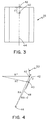
- Figs. 3 provides the background necessary to understand Fig. 4.
- Figs. 3 shows a portion of the disk drive referred to as the slider 26 which holds a read element 40 and a write element 42.
- the slider 26 is attached to an actuator arm depicted by line 48 in Fig. 4.
- the read element 40 and the write element 42 are aligned either parallel to or along the longitudinal axis 44 of the slider.
- the read element 40 and write element 42 may not be precisely aligned.
- the problem is that when either the read element or the write element is positioned over a particular track the other element is offtrack from track 50.
- the amount that one of the elements is offtrack varies as a function of the radius of the track in the case of a radial actuator being followed.
- This problem is known as track misregistration and can and will affect data integrity. Track misregistration must be corrected to allow track pitch or width to get smaller, and thus allow for increased track density without errors.
- Another problem is that repositioning between the write function and the read function on the track takes time and affects the data throughput rate of the disk drive.
- linear actuators which uses a slider as is shown in Fig. 3 which has the read element 40 aligned with the write element 42
- the heads can still be misaligned due to manufacturing error.
- linear actuators may also have a carriage which may be difficult to mount perfectly so the read element 40 and the write element 42 remain on a tangent to the tracks of a disk 34.
- the read element 40 can be tracking over a desired track in a disk drive while the write element 42 does not track over the same desired track. Again, this is track misregistration. It is important to minimize track misregistration to assure that the data is being read from or written to the desired track. It is also important since a well known goal in designing disk drive devices is to increase capacity.
- the invention disclosed in a European patent application EP A-096-418 relates to a magnetic head for magnetic disk suitable for use in a magnetic head where a read/write head and an erase head are placed side by side in the rotation direction of the magnetic disk.
- a gap in the read/write head is placed at a distance from a pair of gaps in the erase head.
- the read/write gap in the read/write head is deviated by a distance in the external circumference direction with respect to a pair of erase gaps in the erase head. But this deviation is fixed, it does not vary according to the movement of the arm to which the read/write and erase heads is affixed.
- the invention disclosed therein is dedicated to magnetic floppy disk and not to rigid disk where tracks are more narrow.
- the actual offset of the read element with respect to the write element is measured which includes the manufacturing tolerances.
- the position offtrack that either the read element or write element is when the read and write element are aligned along the longitudinal axis of the slider can be mathematically described as a function of the cylinder position of the track. This distance is calculated using values measured and stored at the time the disk drive is manufactured and then summed with the read/write centerline offset so that the actual repositioning distance is then determined and the slider can then be repositioned.
- the read element is intentionally offset at an angle from the write element rather than being aligned along the longitudinal axis of the slider for a rotary actuated disk drive.
- the write element could also be offset from the read element.
- the angle of offset is selected to minimize the distance necessary to move the actuator for any track on the disk drive. Since the repositioning distance is minimized the amount of time lost due to repositioning is minimized.
- track misregistration can be minimized which allows for better data integrity and allows smaller track pitch.
- slow down in trhoughput of data due to switching operations on a track can be minimized for a rotary actuator that uses a separate read element and write element.
- the features of the apparatus of the present invention are set in claim 1.
- the apparatus is to be used in connection with the associated method as set in claim 2.
- Fig. 1 is an exploded view of a disk drive.
- Fig. 2 is an exploded view of the actuator arm assembly.
- Fig. 3 is a bottom view of a slider showing a read element and a write element which are aligned along a radial from the actuator arm.
- Fig. 4 is a schematic of the actuator arm with the read element and write element as shown in Fig. 2 attached.
- Fig. 5 is a top view of a disk with an actuator arm having a slider attached thereto shown schematically.
- Fig. 6 is a top cutaway view of a slider with the write element on the radial from the actuator pivot point through the center of the slider and the read element offset therefrom.
- Fig. 7 is a schematic diagram similar to Fig. 5 for a slider with the write element offset from the read element.
- Fig. 1 is an exploded view of a disk drive 10.
- the disk drive 10 includes a housing 12, and a housing cover 14 which, after assembly, is mounted within a frame 16.
- Rotatably attached within the housing 12 on an actuator shaft 18 is an actuator arm assembly 20.
- On the end of the actuator arm assembly 20 includes an E block or comb like structure 22 having a plurality of arms 23. Attached to the separate arms 23 on the comb or E block 22, are load springs 24. Attached at the end of each load spring is a slider 26 which carries a pair of magnetic transducers (shown as a read element and a write element in Figs 3-7).
- a voice coil 28 On the other end of the actuator arm assembly 20 opposite the load springs 24 and the sliders 26 is a voice coil 28.
- a pair of magnets 30 Attached within the housing 12 is a pair of magnets 30.
- the pair of magnets 30 and the voice coil 28 are key parts of a voice coil motor which applies a force to the actuator assembly 20 to rotate it about the actuator shaft 18.
- a spindle shaft 32 Also mounted within the housing 12 is a spindle shaft 32.
- Rotatably attached to the spindle shaft 32 are a number of disks 34. In Fig. 1, eight disks are attached to the spindle shaft 32. As shown in Fig. 1, the disks 34 are attached to the spindle shaft 32 in spaced apart relation.
- An internal motor (not shown) rotates the disks 34.
- Fig. 2 details the actuator arm assembly 20 in an exploded view.
- Each of the arms 23 of the E block or comb assembly 22, except the arms 23 on the top and bottom of the E block 22, carry two load springs.
- the top and bottom arms 23 of the E block 22 have only one load spring 24 since these are used for the top surface of the top disk and the bottom surface of the bottom disk in the stack of disks 34.
- Attached to the load springs 24 are sliders 26 which include magnetic transducers which magnetize the surface of the disk 34 to represent and store desired data.
- each of the disks has a series of concentric tracks onto which the magnetic information is recorded.
- the sliders 26 and the magnetic transducers incorporated therein are moved over the surface of a particular disk 34 so that a magnetic representation of data can be stored in any of the tracks on the disk 34.
- the transducer movement is rotational and about the actuator shaft 18. Rotating the actuator arm assembly 20 causes the slider 26 and the transducer therein to be repositioned over surface of the disk 34.
- Fig. 3 shows a slider 26 which has a read element or head 40 and a write element or head 42.
- the slider has a longitudinal axis 44.
- the read element 40 and the write element 42 are aligned along the longitudinal axis 44 of the slider 26 within a given manufacturing tolerance.
- Fig. 4 is a schematic of a disk drive that uses the slider shown in Fig. 3.
- Fig. 4 includes the axis of rotation 46 of an actuator arm assembly about an actuator shaft.
- the actuator arm is shown schematically as line 48.
- the schematic actuator arm 48 is shown in two positions so as to illustrate a point that will be made in the next paragraph.
- the schematic actuator arm 48 includes the write element 42 and the read element 40 which are shown along line 48 and are separated by a distance d.
- the read element 40 and the write element 42 are shown on the schematic actuator arm depicted by line 48 since the axis of the slider 44 is colinear in this example with the radial from the centerpoint of the axis of rotation 46 of the actuator arm assembly.
- Fig. 4 also shows a data track 50 which is on one of the disks 34 shown in Fig. 1.
- the data track 50 is at a radius RT from the center of the disk 34 (not shown in Fig. 4).
- the radius RT is shown to the write element 42 in one of the positions of the schematic arm depicted as line 48 and the radius of the track RT is also shown to the read element 40 in the second position of the schematic actuator arm 48.
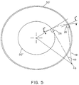
- Fig. 5 deals with skew angles and shows that the skew angles vary as the actuator arm 48 crosses the disk 34.
- the outermost data track 50' and the innermost data track 50" are shown.
- Fig. 5 also shows two positions of the schematic actuator arm 48. One of the positions of the actuator arm has the write element 42 at the back of the slider 26 tracking over track 50' and the other of these positions is with the write element 42 tracking over the track 50".
- the skew angle is the angle between a radial of the disk 34 through the midpoint of the back of the slider 26 and a line perpendicular to the longitudinal axis of the actuator arm 48.
- the skew angle A is associated with the slider 26 when it is positioned over track 50' and the skew angle B is associated with the slider 26 when it is positioned over track 50".
- Simple geometry can also be used to find angles equalling the skew angle as defined above. For example, an angle equal to skew angle A occurs between the longitudinal axis of the load arm depicted as line 48 and a tangent to the track at the midpoint of the back of the slider 26 which contains the write element and which is positioned over the track. Knowing this it can be seen from Fig. 5 that for larger skew angles the offtrack distance between the read and write elements will be greater than for a smaller skew angle.
- Fig. 6 shows a slider 26 having the read element 40 positioned away from the longitudinal axis 44 of the slider 26.
- the view of the slider 26 shown in Fig. 6 is a cutaway view from the top of the slider 26.
- An angle C is defined by the angle between the sliders longitudinal axis 44 and a line 52 between the read element 40 and the write element 42.
- Fig. 7 the type of slider 26 shown in Fig. 6 is depicted in Fig. 7 as a straight line from the centerpoint of the axis of rotation for the actuator arm assembly 20 and then the line 52 making the same angle C between the read element 40 and the write element 42.
- the distance that the write element 42 goes off track while the read element is tracking over a track 50 closer to the inner diameter or tracking over a track near the outer diameter is lessened considerably.
- the time necessary for this change is also lessened which aids in data throughput.
- the angling of the write element with respect to the read element also produces the same benefits when switching from a write operation on a particular track to a read operation on a particular track.
- the angle C can be selected to minimize the off track distance that either the read element 40 or the write element 42 is off track when the other head is in operation.
- the distance and time necessary for repositioning between reading with the read element 40 and writing with the write element 42 or vice versa is minimized in the disk drive for each position.
- the angle C in Figs. 6 and 7 that will minimize the distance that the write element 42 will be off track when the read element 40 is following any track 50 on the disk is determined by measuring the skew angle A at the inner radius (track 50" in Fig. 5) and skew angle B at the outer radius (track 50' in Fig. 5).
- the value for angle C is that which minimizes the distance that the actuator arm must move for repositioning from a read operation to a write operation. Difference in various performance characteristics between the inner and outer data tracks may make the optimum angle C slightly different than the calculated angle C.
- the angle C is selected to minimize the distance which the actuator arm must move to switch between a write operation and a read operation or vice versa, at approximately midway between the track 50' at the outer diameter and the track 50" at the inner diameter, the read element 40 and the write element 44 will both pass over a track at the same time. At this track, no movement will be necessary to switch between reading with the read element 40 and writing with the write element 42.
- the actuator arm when switching between reading and writing or vice versa, the actuator arm generally must be moved so that the head about to be used is positioned over the track.
- the angle C has been optimized and set, there can be differences in the actual offset between the read element 40 and the write element 42 in a particular slider 26.
- the offset between the write element 42 and the read element 40 will not be the same as the offset associated with the angle C. Manufacturing tolerances will cause the actual offset to be slightly different.
- the physical center of a read element 40 or a write element 42 may not correspond to its magnetic center. These are just some of the factors that may cause the actual offset of the write element from the read element 40 to differ from the calculated case.
- Trigonometry can be used to yield an essentially linear function which describes the distance off track a write element 42 is with respect to a read element 40 (as shown in Figs. 3 and 4) while the read element is on track as a function of the particular cylinder.
- the cylinder location is defined by the servo tracks on the servo surface in the disk drive.
- the same linear function will describe the amount offtrack a read element is when the write element is on track as a function of the cylinder location except for the sign of the offset.
- the linear function is used to determine the amount of offtrack for the case where the read element and write element are aligned.
- Determination of the actual offset of the write element 42 from the read element 40 is accomplished by writing temporary servo reference information along the edge of the disk 34 beyond the outer radius of the data region.
- the servo reference information is temporarily written from outer edge of a disk toward the inner radius of the disk 34 over a few tracks in the reference area.
- the servo reference information is then read using the read element and the amount of bias read by the read element 40 is retained. Writing from the outer edge toward the inner radius is considered moving in a positive direction.
- the next step in determining the actual offset is to write permanent servo reference information toward the outer radius in the region of the disk beyond the data tracks. Again the read element 40 is then positioned to the center of the cylinder as defined by the servo tracks on the servo surface. The servo reference tracks are then read and the amount of bias is then observed and retained.
- the actual offset between the center of the read element and the center of the write element can be determined.
- the total width of the write element can be determined.
- the slider is then moved to a position near the inner diameter of the disk 34 and the above steps are repeated. Namely, a temporary servo reference track is initially written in one direction, then in the other. From this information the write width and the offset between the write element and the read element can be determined.
- the offset at the inner radius and the outer radius are significant due to the distance d between the read element and the write element and the angle the heads are rotated. Thus the difference in the offsets at the inner radius and the outer radius gives the effect due to the distance d.
- the offsets at the extremes are generally positive and negative in sign and are statistically comparable in magnitude.
- this invention is applicable to any system having a separate read element and write element to minimize track misregistration.
- offsetting the read or write element can be used in any environment where a rotary actuator is used to access a circular or spiral track, such as optical disks or disks with magnetic layers.
Landscapes
- Moving Of Heads (AREA)
- Moving Of The Head To Find And Align With The Track (AREA)
- Adjustment Of The Magnetic Head Position Track Following On Tapes (AREA)
Applications Claiming Priority (2)
| Application Number | Priority Date | Filing Date | Title |
|---|---|---|---|
| US59159690A | 1990-10-02 | 1990-10-02 | |
| US591596 | 1990-10-02 |
Publications (2)
| Publication Number | Publication Date |
|---|---|
| EP0479703A1 EP0479703A1 (en) | 1992-04-08 |
| EP0479703B1 true EP0479703B1 (en) | 1997-04-02 |
Family
ID=24367098
Family Applications (1)
| Application Number | Title | Priority Date | Filing Date |
|---|---|---|---|
| EP91480142A Expired - Lifetime EP0479703B1 (en) | 1990-10-02 | 1991-09-06 | Method and apparatus for positioning transducers |
Country Status (9)
| Country | Link |
|---|---|
| US (1) | US5682274A (enExample) |
| EP (1) | EP0479703B1 (enExample) |
| JP (1) | JPH04232610A (enExample) |
| KR (1) | KR960015921B1 (enExample) |
| CN (1) | CN1028574C (enExample) |
| DE (1) | DE69125447T2 (enExample) |
| MY (1) | MY110421A (enExample) |
| SG (1) | SG46192A1 (enExample) |
| TW (1) | TW226467B (enExample) |
Families Citing this family (30)
| Publication number | Priority date | Publication date | Assignee | Title |
|---|---|---|---|---|
| US5715105A (en) * | 1992-09-28 | 1998-02-03 | Hitachi, Ltd. | Method of and apparatus for recording on and reproducing from disk-type recording medium having recording tracks with sectors each having an ID area and a data area |
| JP3395235B2 (ja) * | 1993-02-09 | 2003-04-07 | ソニー株式会社 | 情報記録ディスク |
| US5444589A (en) * | 1993-12-02 | 1995-08-22 | International Business Machines Corporation | Rotary actuator disk drive with identical dual-element read/write transducers |
| KR950020658A (ko) * | 1993-12-07 | 1995-07-24 | 새끼자와 다다시 | 자기디스크장치 |
| DE4447813B4 (de) * | 1993-12-07 | 2006-05-24 | Fujitsu Ltd., Kawasaki | Aufzeichnungs-/Wiedergabevorrichtung |
| JP3135447B2 (ja) * | 1994-01-27 | 2001-02-13 | 富士通株式会社 | 磁気ディスクドライブの制御方法及びその装置 |
| JPH07320247A (ja) * | 1994-05-23 | 1995-12-08 | Internatl Business Mach Corp <Ibm> | Mrヘッド用サーボ方法及びハードディスクシステム |
| US5654842A (en) * | 1994-08-30 | 1997-08-05 | Sony Corporation | Head displacement measuring method and apparatus and data recording/reproducing method and apparatus |
| US6252732B1 (en) * | 1994-12-01 | 2001-06-26 | International Business Machines Corporation | Method and apparatus for correcting systematic errors in timing pattern generation |
| US6078450A (en) * | 1994-12-01 | 2000-06-20 | International Business Machines Corporation | Method and apparatus for correcting for random errors in timing pattern generation |
| US6898035B1 (en) * | 1994-12-01 | 2005-05-24 | Hitachi Global Storage Technologies Netherlands B.V. | Method and apparatus for correcting for systematic errors in timing pattern generation |
| WO1996039692A1 (en) * | 1995-06-06 | 1996-12-12 | Maxtor Corporation | Mr head differential micro-jog |
| GB2332523B (en) * | 1997-12-16 | 2002-04-10 | Havant Internat Ltd | Tool,apparatus and method for testing a fixture |
| JP3080364B2 (ja) * | 1997-12-25 | 2000-08-28 | インターナショナル・ビジネス・マシーンズ・コーポレ−ション | ディスクドライブ装置、シーク制御装置 |
| US6195230B1 (en) | 1998-04-27 | 2001-02-27 | Intel Corporation | Disk head assembly with multiple read and/or write transducers for improved performance |
| US6320718B1 (en) * | 1999-01-07 | 2001-11-20 | Western Digital Technologies, Inc. | Disk drive with zero read offset in reserved area and method of making same |
| US6545841B1 (en) * | 1999-02-08 | 2003-04-08 | Seagate Technology Llc | Strategy for read/write spacing requirement |
| US6765737B1 (en) | 1999-04-21 | 2004-07-20 | Seagate Technology Llc | Variable track densities on a recording medium to compensate for non-repeatable runout (NRRO) error |
| US6359749B1 (en) | 1999-10-15 | 2002-03-19 | International Business Machines Corporation | Dual element head with radial offset optimized for minimal write-to-read track error |
| WO2001052260A1 (en) * | 2000-01-10 | 2001-07-19 | Seagate Technology Llc | Servo track writing using extended copying with head offset |
| US6369969B1 (en) * | 2001-02-28 | 2002-04-09 | Western Digital Technologies, Inc. | Disk drive for detecting a polarity error of a magnetoresistive head by detecting a sync mark |
| US7265921B2 (en) * | 2004-02-10 | 2007-09-04 | Hitachi Global Storage Technologies Netherlands B.V. | Method to increase the amount of customer data on a hard disk drive |
| US7372276B2 (en) * | 2005-02-16 | 2008-05-13 | Goldak, Inc. | Digital locating system and device for underground object detection |
| US7256956B2 (en) * | 2005-03-16 | 2007-08-14 | Matsushita Electric Industrial Co., Ltd. | Propagation self servowrite using self-written spiral signals for in-process calibration |
| CN1862743B (zh) * | 2005-05-13 | 2012-01-18 | 大日科技股份有限公司 | 滚珠开关 |
| US8009388B2 (en) * | 2006-10-10 | 2011-08-30 | Seagate Technology Llc | Method for increasing storage capacity and a transducer configuration incorporating the same |
| US7880987B2 (en) * | 2007-03-30 | 2011-02-01 | Seagate Technology Llc | Media servowriter/certifier |
| KR20080108768A (ko) * | 2007-06-11 | 2008-12-16 | 삼성전자주식회사 | 헤드슬라이더 및 이를 구비한 하드디스크 드라이브 |
| US8154817B2 (en) * | 2008-09-05 | 2012-04-10 | Doug Carson & Associates, Inc. | Compensation for different transducer translation path geometries |
| US20110134558A1 (en) * | 2009-12-08 | 2011-06-09 | Kabushiki Kaisha Toshiba | Disk device, head distance calculation method, and offset control method |
Family Cites Families (15)
| Publication number | Priority date | Publication date | Assignee | Title |
|---|---|---|---|---|
| US4388655A (en) * | 1977-09-13 | 1983-06-14 | Zenzefilis George E | Method and apparatus for recording and reproducing video and sound |
| JPS5860423A (ja) * | 1981-10-07 | 1983-04-09 | Hitachi Metals Ltd | 磁気ヘツド装置 |
| JPS58196619A (ja) * | 1982-05-10 | 1983-11-16 | Hitachi Ltd | 磁気ヘツドおよびその製造方法 |
| JPS58215717A (ja) * | 1982-06-09 | 1983-12-15 | Hitachi Ltd | 磁気ヘツド |
| JPS6061910A (ja) * | 1983-09-16 | 1985-04-09 | Mitsubishi Electric Corp | 磁気ヘツド組立体 |
| FR2557722B1 (fr) * | 1983-12-30 | 1986-04-11 | Bull Sa | Procede d'ecriture d'informations sur un support d'enregistrement |
| JPS62295213A (ja) * | 1986-06-13 | 1987-12-22 | Sony Corp | 磁気デイスク装置 |
| JPS6398820A (ja) * | 1986-10-15 | 1988-04-30 | Sony Corp | 磁気デイスクの記録方式 |
| US4802033A (en) * | 1986-11-07 | 1989-01-31 | Eastman Kodak Company | Predictive positioning offset compensation for high TPI disk systems |
| JPH01154311A (ja) * | 1987-12-11 | 1989-06-16 | Toshiba Corp | 磁気ディスク装置 |
| JPH01184675A (ja) * | 1988-01-11 | 1989-07-24 | Nec Corp | 磁気記録装置およびトラックアクセス方式 |
| US4969059A (en) * | 1988-03-28 | 1990-11-06 | Rigidyne Corporation | Offset nulling system for computer disk drives |
| US4945427A (en) * | 1988-06-13 | 1990-07-31 | International Business Machines Corporation | Magnetic disk recording with variable track width and variable track density |
| US5073833A (en) * | 1989-11-13 | 1991-12-17 | International Business Machines Corporation | Dual sector servo system for disk file with separate read and write heads |
| US5235478A (en) * | 1989-12-15 | 1993-08-10 | Sony Corporation | Disc drive apparatus with servo tracks offset from data tracks |
-
1991
- 1991-08-22 JP JP3233805A patent/JPH04232610A/ja active Pending
- 1991-09-06 EP EP91480142A patent/EP0479703B1/en not_active Expired - Lifetime
- 1991-09-06 SG SG1996000419A patent/SG46192A1/en unknown
- 1991-09-06 DE DE69125447T patent/DE69125447T2/de not_active Expired - Fee Related
- 1991-09-25 MY MYPI91001730A patent/MY110421A/en unknown
- 1991-09-29 CN CN91109434A patent/CN1028574C/zh not_active Expired - Fee Related
- 1991-09-30 KR KR1019910017062A patent/KR960015921B1/ko not_active Expired - Fee Related
- 1991-12-31 TW TW080110281A patent/TW226467B/zh active
-
1995
- 1995-02-22 US US08/392,276 patent/US5682274A/en not_active Expired - Lifetime
Also Published As
| Publication number | Publication date |
|---|---|
| KR960015921B1 (ko) | 1996-11-23 |
| CN1060919A (zh) | 1992-05-06 |
| HK1000069A1 (en) | 1997-11-07 |
| DE69125447T2 (de) | 1997-09-25 |
| JPH04232610A (ja) | 1992-08-20 |
| SG46192A1 (en) | 1998-02-20 |
| EP0479703A1 (en) | 1992-04-08 |
| CN1028574C (zh) | 1995-05-24 |
| US5682274A (en) | 1997-10-28 |
| DE69125447D1 (de) | 1997-05-07 |
| KR920008679A (ko) | 1992-05-28 |
| MY110421A (en) | 1998-05-30 |
| TW226467B (enExample) | 1994-07-11 |
Similar Documents
| Publication | Publication Date | Title |
|---|---|---|
| EP0479703B1 (en) | Method and apparatus for positioning transducers | |
| US7082007B2 (en) | Method to achieve higher track density by allowing only one-sided track encroachment | |
| US6101063A (en) | Methods and systems for self-servowriting including maintaining a reference level within a usable dynamic range | |
| US5343347A (en) | Magnetic disk storage module with multiple sets of actuator arms for simultaneous read/write operations at different circumferential locations within the disk stack | |
| US5257149A (en) | Disc drive with offset address field | |
| US5343345A (en) | Magnetic disk storage apparatus with multiple sets of actuator arms for read/write operations at different circumferential locations within the disk stack | |
| US6765737B1 (en) | Variable track densities on a recording medium to compensate for non-repeatable runout (NRRO) error | |
| KR20010113707A (ko) | 하드디스크 드라이브의 서보 기록 방법 | |
| WO1999024971A2 (en) | Magnetic recording/reproduction device | |
| US7511912B2 (en) | Writing multiple servo sector patterns to improve servo sector alignment on multiple surfaces | |
| US6724558B2 (en) | Servo writing in a disc drive with substantially identical heads having read and write elements in a radial offset position | |
| KR100641458B1 (ko) | 매설 서보 패턴화 매체 | |
| KR100373879B1 (ko) | 디스크드라이브의데이터필드에대한이중식별 | |
| US6980386B2 (en) | Apparatus and method for writing data to an information storage disc | |
| US6724562B1 (en) | Segmented constant angle trackpitch | |
| US6049442A (en) | Multiply-written servo burst patterns for minimizing position error in servo disk drives | |
| CN1110824A (zh) | 用于在直接存取存储器件中进行相位调制伺服定位的方法和设备 | |
| HK1000069B (en) | Method and apparatus for positioning transducers | |
| US6091566A (en) | Magnetoresistive head and hard drive system having offsets from center of the servo area to minimize microjogging | |
| US7012786B2 (en) | Magnetic head | |
| US6538837B1 (en) | Method of aligning servo wedges in a disc drive | |
| KR100233669B1 (ko) | 트랙 쉬프트량 보상을 위한 서보버스트 기록방법및 서보제어방법 | |
| Ottesen | Future servo technologies for hard disk drives | |
| JPS6341658Y2 (enExample) | ||
| KR20030086927A (ko) | 반응 질량체 듀얼-스테이지 액츄에이터 및 센서 |
Legal Events
| Date | Code | Title | Description |
|---|---|---|---|
| PUAI | Public reference made under article 153(3) epc to a published international application that has entered the european phase |
Free format text: ORIGINAL CODE: 0009012 |
|
| AK | Designated contracting states |
Kind code of ref document: A1 Designated state(s): DE FR GB |
|
| 17P | Request for examination filed |
Effective date: 19920817 |
|
| 17Q | First examination report despatched |
Effective date: 19941205 |
|
| GRAG | Despatch of communication of intention to grant |
Free format text: ORIGINAL CODE: EPIDOS AGRA |
|
| GRAH | Despatch of communication of intention to grant a patent |
Free format text: ORIGINAL CODE: EPIDOS IGRA |
|
| GRAH | Despatch of communication of intention to grant a patent |
Free format text: ORIGINAL CODE: EPIDOS IGRA |
|
| GRAA | (expected) grant |
Free format text: ORIGINAL CODE: 0009210 |
|
| AK | Designated contracting states |
Kind code of ref document: B1 Designated state(s): DE FR GB |
|
| REF | Corresponds to: |
Ref document number: 69125447 Country of ref document: DE Date of ref document: 19970507 |
|
| ET | Fr: translation filed | ||
| PLBE | No opposition filed within time limit |
Free format text: ORIGINAL CODE: 0009261 |
|
| STAA | Information on the status of an ep patent application or granted ep patent |
Free format text: STATUS: NO OPPOSITION FILED WITHIN TIME LIMIT |
|
| 26N | No opposition filed | ||
| PGFP | Annual fee paid to national office [announced via postgrant information from national office to epo] |
Ref country code: FR Payment date: 19990917 Year of fee payment: 9 |
|
| PG25 | Lapsed in a contracting state [announced via postgrant information from national office to epo] |
Ref country code: FR Free format text: LAPSE BECAUSE OF NON-PAYMENT OF DUE FEES Effective date: 20010531 |
|
| REG | Reference to a national code |
Ref country code: FR Ref legal event code: ST |
|
| REG | Reference to a national code |
Ref country code: GB Ref legal event code: IF02 |
|
| REG | Reference to a national code |
Ref country code: GB Ref legal event code: 732E |
|
| PGFP | Annual fee paid to national office [announced via postgrant information from national office to epo] |
Ref country code: GB Payment date: 20080820 Year of fee payment: 18 |
|
| PGFP | Annual fee paid to national office [announced via postgrant information from national office to epo] |
Ref country code: DE Payment date: 20080908 Year of fee payment: 18 |
|
| GBPC | Gb: european patent ceased through non-payment of renewal fee |
Effective date: 20090906 |
|
| PG25 | Lapsed in a contracting state [announced via postgrant information from national office to epo] |
Ref country code: DE Free format text: LAPSE BECAUSE OF NON-PAYMENT OF DUE FEES Effective date: 20100401 |
|
| PG25 | Lapsed in a contracting state [announced via postgrant information from national office to epo] |
Ref country code: GB Free format text: LAPSE BECAUSE OF NON-PAYMENT OF DUE FEES Effective date: 20090906 |