EP0479318A2 - Gasfeuerzeug mit Sicherheitsvorrichtung - Google Patents
Gasfeuerzeug mit Sicherheitsvorrichtung Download PDFInfo
- Publication number
- EP0479318A2 EP0479318A2 EP91116991A EP91116991A EP0479318A2 EP 0479318 A2 EP0479318 A2 EP 0479318A2 EP 91116991 A EP91116991 A EP 91116991A EP 91116991 A EP91116991 A EP 91116991A EP 0479318 A2 EP0479318 A2 EP 0479318A2
- Authority
- EP
- European Patent Office
- Prior art keywords
- lock member
- ignition lever
- ignition
- lighter
- safety device
- Prior art date
- Legal status (The legal status is an assumption and is not a legal conclusion. Google has not performed a legal analysis and makes no representation as to the accuracy of the status listed.)
- Granted
Links
- 230000004044 response Effects 0.000 claims abstract description 21
- 239000000446 fuel Substances 0.000 claims description 46
- 230000007246 mechanism Effects 0.000 claims description 46
- 230000000994 depressogenic effect Effects 0.000 claims description 31
- 230000000881 depressing effect Effects 0.000 claims description 11
- 239000000463 material Substances 0.000 claims description 9
- 239000011347 resin Substances 0.000 claims description 5
- 229920005989 resin Polymers 0.000 claims description 5
- 239000012858 resilient material Substances 0.000 claims description 4
- 230000000717 retained effect Effects 0.000 claims description 2
- 230000001105 regulatory effect Effects 0.000 claims 4
- 239000007789 gas Substances 0.000 description 47
- 210000003811 finger Anatomy 0.000 description 26
- 210000003813 thumb Anatomy 0.000 description 9
- 239000002737 fuel gas Substances 0.000 description 6
- 238000004519 manufacturing process Methods 0.000 description 6
- 230000009471 action Effects 0.000 description 4
- 230000002411 adverse Effects 0.000 description 4
- XEEYBQQBJWHFJM-UHFFFAOYSA-N Iron Chemical compound [Fe] XEEYBQQBJWHFJM-UHFFFAOYSA-N 0.000 description 2
- 230000000977 initiatory effect Effects 0.000 description 2
- 230000006872 improvement Effects 0.000 description 1
- 229910052742 iron Inorganic materials 0.000 description 1
- 230000009467 reduction Effects 0.000 description 1
Images















Classifications
-
- F—MECHANICAL ENGINEERING; LIGHTING; HEATING; WEAPONS; BLASTING
- F23—COMBUSTION APPARATUS; COMBUSTION PROCESSES
- F23Q—IGNITION; EXTINGUISHING-DEVICES
- F23Q2/00—Lighters containing fuel, e.g. for cigarettes
- F23Q2/16—Lighters with gaseous fuel, e.g. the gas being stored in liquid phase
- F23Q2/164—Arrangements for preventing undesired ignition
Definitions
- This invention relates to a gas lighter with a safety device, and more particularly to a so-called child resistant gas lighter having a safety device which prevents depression of the ignition lever of the lighter to prevent inadvertent ignition while the gas lighter is not used.
- a gas lighter is a convenient tool which can easily be ignited by depression of the ignition lever, it is not preferable in view of safety that those who do not know proper use of the lighter like a child inadvertently ignites it.
- the lock member is manually moved between a locking position and a releasing position, and the lock member remains in the releasing position and the safety device cannot function unless the lock member is manually returned to the locking position after it is moved to the releasing position and the the gas lighter is ignited. That is, the lock mechanism must be operated again after it is released and the lighter is used. Otherwise, the lock mechanism cannot function.
- a further improved lock mechanism there has been a demand for a further improved lock mechanism.
- the lock member is formed of resilient material and accordingly, the lock member can return to the locking position under its own resiliency after it is moved to the releasing position.
- an auto-return safety device in which the lock member is moved along a linear path to the releasing position, thereby facilitating release of the lock mechanism, and at the same time, it can be held in the releasing position with the finger with which the ignition mechanism is actuated, without using another finger.
- the safety device also has drawbacks for practical use. That is, in the safety device disclosed in the Japanese Unexamined Utility Model Publication No. 1(1989)-178456, the lock member is incorporated in the ignition lever, which is actuated to ignite the lighter, so that the lock member can be moved to the releasing position with the thumb for operating the ignition lever, and the ignition lever is actuated with the thumb after the lock member is moved to the releasing position with the thumb.
- the safety device release of the lock mechanism is facilitated.
- the safety device is disadvantageous in that when the ignition lever is actuated with the thumb after the lock member is moved to the releasing position with the same finger, the lock member can be inadvertently released from the thumb and can return to the locking position. Accordingly, also in the safety device, the lock member cannot be steadily released, which adversely affects ease of releasing the lock mechanism in the gas lighter which is generally operated with a single finger, e.g. the thumb, and leads to different results depending on persons who use the lighter as in the preceding examples.
- any one of the conventional child resistant safety device has drawbacks for practical use, and accordingly there has been a demand for a child resistant safety device which has an enhanced safety and is easy to handle.
- the primary object of the present invention is to provide a gas lighter with a safety device which is excellent both in ease of handling and in safety function and which has an auto-return lock mechanism which can be automatically restored without operation after it is released and the lighter is ignited, the ease of handling being improved by arranging the lock mechanism so that the lock mechanism is released by movement of a lock member along a linear path to a releasing position and the lock member is automatically held in the releasing position to permit the user to actuate the ignition mechanism with either the finger which has been used to release the lock mechanism or any finger else independently from action of releasing the lock mechanism.
- Another object of the present invention is to provide a gas lighter with a safety device which is further improved in stability and ease of handling in the locked state.
- Still another object of the present invention is to provide a gas lighter with a safety device which permits rationalization of the assembling steps, improvement in assembling accuracy of the safety device thereby further facilitating handling of the safety device and reduction of the manufacturing cost.
- the gas lighter with a safety device in accordance with the present invention is characterized by having a lock member which is able to linearly move between a locking position where it prevents depression of an ignition lever and a releasing position where it allows depression of the ignition lever and is urged to the locking position, a holding means which is caused to hold the lock member in the releasing position in response to movement of the lock member to the releasing position, a releasing means which releases the lock member from the holding means in response to depression of the ignition lever, thereby permitting the lock member to move away from the releasing position, and a temporary holding means which temporarily holds the lock member in the releasing position or the vicinity thereof until the ignition lever returns to the original position.
- the lock member is foldable in the locking position.
- the gas lighter is formed of a lighter body and an intermediate casing which is formed separately from the lighter body and in which the safety device (comprising the lock member, the spring, the holding means, the releasing means and the like) and an ignition mechanism are incorporated.
- the safety device and the ignition mechanism are incorporated in the intermediate casing before the intermediate casing is incorporated in the lighter body.
- the lock lever prevents depression of the ignition lever and does not permit inadvertent ignition of the lighter while the gas lighter is not used, and at the same time, it is automatically returned to the locking position after it is moved to the releasing position to permit ignition and the ignition lever returns to the original position after ignition.
- the lock member since the lock member is linearly moved between the locking position and the releasing position, it can be easily operated.
- the ignition mechanism can be actuated with either the finger which has been used to release the lock mechanism or any finger else independently from action of releasing the lock mechanism, whereby the safety and the ease of handling are both improved and the gas lighter can be operated steadily without depending on the person who uses it.
- the lock member in the case of the embodiment in which the lock member is foldable in the locking position, the lock member can be surely held in the locking position and at the same time ease of handling the lighter can be improved by folding the lock member in the locking position.
- the assembly comprising the intermediate casing and the components incorporated therein can be assembled separately from the lighter body and can be combined with the lighter body later as a unit, which affords more freedom to the assembly line in the manufacturing steps and permits rationalization of the manufacturing steps.
- the safety device and the ignition means can be incorporated in the lighter body after assembled together, the assembling accuracy is improved, whereby precision of the safety device is improved and handling of the lighter is further facilitated.
- the intermediate casing may be formed of material which is less expensive than the material for forming the lighter body which must have high heat resistance and accordingly is relatively expensive, whereby the manufacturing cost of the lighter can be reduced.
- FIGS 1 to 3 and Figure 10 show the state of the gas lighter in accordance with this embodiment in which the ignition lever is locked.
- an ignition lever 2 which releases fuel gas and actuates an ignitor when it is depressed is provided with a pair of projections 2a and 2b on the lower surface thereof.
- the projections 2a and 2b extend downward and are obliquely spaced from each other.
- the ignition lever 2 is formed of resin material having high heat resistance and is provided with a depressing portion 12c at one end and with a forked engagement portion 12d at the other end ( Figure 31), the forked engagement portion 12d being engaged with the neck of a fuel valve (not shown) so that fuel gas is discharged from the valve in response to depression of the depressing portion with a finger.
- the lock member 4 is provided between the ignition lever 2 and the lighter body 3 to be slidable transversely to the ignition lever 2 between a locking position in which it prevents depression of the ignition lever 2 and a releasing position in which it allows depression of the ignition lever 2.
- a hook 4e which is fitted in a groove 3a formed on the lighter body 3 and retains the lock member 4 on the lighter body 3 to be slidable thereon is formed on the lower surface of the lock member 4. (See Figure 3)
- the lock member 4 is formed of resin material which can be readily restored after deformation and is highly slidable, and has a spring-like arm 4a whose tip abuts against a part 5 of the lighter body 3.
- the lock member 4 is urged toward the locking position shown in Figures 1 to 3 by the arm 4a.
- the projection 2a of the ignition lever 2 abuts against the upper surface 4c of the lock member 4 and prevents depression of the ignition lever 2, and the outer end 4b of the lock member 4 projects outside the lighter body 3.
- the lighter body 3 is provided with a holding member 8 which is formed in a rectangular recess 6 formed on the upper part of the lighter body 3.
- the holding member 8 is a cantilever-like portion which is formed integrally with the lighter body 3 to be resiliently deformed.
- a rightangled extension 8c is formed on the tip of the holding member 8, and a protrusion 8a adapted to be engaged with the engagement recess 4f is formed at the corner. Further a projection 8b is formed on the tip of the extension 8c to extend upward.
- the projection 8b is positioned just below the projection 2b of the ignition lever 2 and is pushed downward when the ignition lever 2 is depressed, whereby the holding member 8 is resiliently deformed downward and the protrusion 8a is disengaged from the engagement recess 4f of the lock member 4.
- the ignition lever 2 is provided with an engagement portion which engages with the lock member 4 released from the holding member 8 and temporarily holds the lock member 4 in the releasing position until the ignition lever 2 moves upward from the depressed position to the position before depression.
- the projection 2a functions as the engagement portion.
- the engagement portion may be formed separately from the projection 2a, it is preferred that the projection 2a be used also as the engagement portion in view of simplification of the structure.
- a spring 7 which abuts against the hook 4e of the lock member 4 at one end with the other end fixed to the lighter body 3 as shown in Figures 14 and 15 may be used instead of the arm 4a.
- the lock member 4 When the lighter is not used, the lock member 4 is in the locking position shown in Figures 1 to 3 and 10 where the outer end 4b of the lock member 4 projects outside the lighter body 3 and the projection 2a of the ignition lever 2 is in abutment against the upper surface 4c of the lock member 4 as described above and the ignition lever 2 cannot be depressed. Accordingly, in this state, the lighter cannot be ignited and inadvertent ignition by children or the like is prevented.
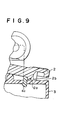
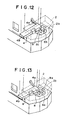
- the lock member 4 In response to depression of the ignition lever 2, the projection 2b on the lower surface of the ignition lever 2 pushes the projection 8b of the holding member 8, whereby the holding member 8 is deformed downward as shown in Figures 7 to 9 and 12 and 13 and the protrusion 8a is disengaged from the engagement recess 4f of the lock member 4. Accordingly, the lock member 4 tends to return to the locking position since it is spring-urged toward there. However, since the projection 2a of the ignition lever 2 is still received in the cutaway portion 4d at this time and since the former is received in the latter with a slight play, the lock member 4 is moved from the releasing position toward the locking position by a small distance and is held there. That is, the lock member 4 is temporarily held in a position slightly deviated toward the locking position from the position where the protrusion 8a of the holding member 8 is disengaged from the engagement recess 4f of the lock member 4.
- the lock member 4 prevents depression of the ignition lever 2 thereby preventing inadvertent ignition of the lighter while the lighter is not used, and the lock member 4 is automatically returned to the locking position after it is moved to the releasing position and the lighter is ignited.
- the lock mechanism is automatically restored without operation after it is once released and the lighter is ignited, and accordingly, an extremely safe child resistant gas lighter can be realized.
- the lock member 4 is slidable sideways (in the vertical direction in Figure 1) so that it is pushed in the transverse direction of the lighter body 3, it may be arranged to be slidable in the longitudinal direction (left and right in Figure 1).
- Figures 16 to 22, 33 and 37 show a gas lighter with a safety device in accordance with a second embodiment of the present invention when it is not used, i.e., when the lock member is in the locking position.
- an ignition lever 12 which releases fuel gas and actuates an ignitor when it is depressed is provided with a pair of projections 12a and 12b on the lower surface thereof.
- the projections 12a and 12b extend downward and are obliquely spaced from each other.
- a lock member 14 is provided below the ignition lever 12 to be slidable in the direction in which the ignition lever 12 extends between a locking position in which it prevents depression of the ignition lever 12 and a releasing position in which it allows depression of the ignition lever 12.
- a hook 14e which is fitted in a groove 13b formed on an intermediate casing 13a, which is provided on a lighter body 13, and retains the lock member 14 on the intermediate casing 13a to be slidable thereon is formed on the lower surface of the lock member 14.
- the intermediate casing 13a is formed of resin material which has high resistance to heat and impact and is readily restorable after deformation.
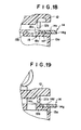
- the lock member 14 has a spring 15 which is compressed between a spring retaining surface 14h of the hook 14e and a vertical wall portion 13c of the intermediate casing 13a and is urged toward the locking position shown in Figures 16 to 19 by the spring 15.
- the projection 12a of the ignition lever 12 abuts against the upper surface 14c of the lock member 14 and prevents depression of the ignition lever 12, and the outer end 14g of the lock member 14 projects outside the lighter body 13.
- the intermediate casing 13a is provided with a holding member 18 which is formed on a wall portion of a rectangular recess 16 formed on the upper part of the intermediate casing 13a ( Figure 16) .
- the holding member 18 has a cantilever-like arm 18c which is formed integrally with the intermediate casing 13a to be resiliently deformed.
- a rightangled extension is formed on the tip of the holding member 18, and a protrusion 18a adapted to be engaged with the engagement recess 14f is formed at the corner. Further a projection 18b is formed on the tip of the extension.
- the projection 18b is positioned just below the projection 12b of the ignition lever 12 and is pushed downward when the ignition lever 12 is depressed, whereby the holding member 18 is resiliently deformed downward and the protrusion 18a is disengaged from the engagement recess 14f of the lock member 14.
- the ignition lever 12 is provided with an engagement portion which engages with the lock member 14 released from the holding member 18 and temporarily holds the lock member 14 in the releasing position until the ignition lever 12 moves upward from the depressed position to the position before depression.
- the projection 12a functions as the engagement portion. Though the engagement portion may be formed separately from the projection 12a, it is preferred that the projection 12a be used also as the engagement portion in view of simplification of the structure.
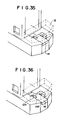
- the lock member 14 When the lighter is not used, the lock member 14 is in the locking position shown in Figures 16, 33 and 37 as described above and the ignition lever 12 cannot be depressed. Accordingly, in this state, the lighter cannot be ignited and inadvertent ignition by children or the like is prevented.
- the lock member 14 prevents depression of the ignition lever 12 thereby preventing inadvertent ignition of the lighter while the lighter is not used, and the lock member 14 is automatically returned to the locking position after it is moved to the releasing position and the lighter is ignited.
- the lock mechanism is automatically restored without operation after it is once released and the lighter is ignited, and accordingly, an extremely safe child resistant gas lighter can be realized.
- Figure 41 is a perspective view showing the ignition lever 12
- Figure 42 is a perspective view showing the back side of the ignition lever as viewed in one direction
- Figure 43 is a perspective view showing the back side of the ignition lever as viewed in another direction
- Figure 44 is a perspective view showing the lock member 14 employed in the embodiment
- Figure 45 is a perspective view showing the back side of the lock member 14 as viewed in one direction
- Figure 46 is a perspective view showing the back side of the lock member 14 as viewed in another direction
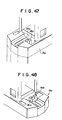
- Figure 47 is a perspective view as viewed in one direction showing the intermediate casing 13a provided on the lighter body 13 employed in the embodiment
- Figure 48 is a perspective view as viewed in another direction showing the intermediate casing 13a.
- the means for urging the lock member 14 to the locking position is the spring 15 which is compressed between a side surface of the hook 14e of the lock member 14 and the intermediate casing 13a.
- the lock member 14 is slidable in the longitudinal direction as in the embodiment shown in Figures 16 to 40, and the arrangement and the operation of each part is substantially the same and accordingly will not be described here.
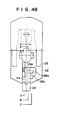
- the parts shown in Figures 49 to 58 are given reference numerals obtained by adding 10 to the reference numerals which are given to the corresponding parts in Figures 16 to 58.
- Figure 50 is a cross-sectional view taken along line A-A in Figure 49
- Figure 52 is a cross-sectional view taken along line B-B in Figure 49.
- the lock member 24 has an outer end portion 26 which projects outside the lighter body 23, and the lock member 24 is moved to the releasing position from the locking position when the outer end portion 26 is pushed into the lighter body 23.
- the outer end portion 26 of the lock member 24 is foldable about a pivot 25, and when the lighter is not used, the outer end portion 26 is folded, whereby the lock member 24 can be surely held in the locking position and at the same time ease of handling the lighter can be improved.
- the outer end portion 26 is first unfolded as shown in Figure 52 and then the lock member 24 is moved from the locking position shown in Figure 52 to the releasing position shown in Figures 53 to 55 so that the depression of the ignition lever 22 is permitted.
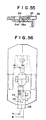
- Figure 56 is a plan view of the lighter with the lock member 24 in the temporarily-held state
- Figure 57 is a cross-sectional view taken along A-A in Figure 56 showing the lock member 24 in the temporarily-held state
- Figure 58 is a cross-sectional view taken along line B-B in Figure 56 showing the lock member 24 in the temporarily-held state.
- the Figures 56 to 58 respectively correspond to Figures 26 to 28 in the second embodiment.
- the lock member may be arranged to be pushed into the lighter body from the opposite side, i.e., from the wind shield side.
- the lock member 34 is pushed into the lighter body 33 along the upper surface of the intermediate casing 33a from the side near the wind shield 30.
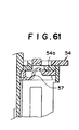
- a coil spring 47 retained between the hook 44e of the lock member 44 and a part of the intermediate casing 43a as shown in Figure 60, or a spring 57 formed integrally with a part 54a of the lock member 54 as shown in Figure 61 may be used.
- the material for forming such resilient members need not be limited to iron. For example, they may be made of plastic material.
- the lock member 4 may be urged to the locking position by other means.
- a push button may be fixed to the lock member 4 and may be formed of a resilient material or provided with a coil spring so that the lock member 4 is urged to the locking position under the resiliency of the push button itself or the coil spring.
- the holding member 18 or 28 extends inward to be resiliently deformable with its one end supported on a side of the lighter body 23 or the intermediate casing 13a
- the holding member may extend outward to be resiliently deformable with its one end supported inside the lighter body 23 or the intermediate casing 13a.
- Figures 62 to 66 Such an embodiment is shown in Figures 62 to 66.
- This embodiment is substantially the same as the embodiment shown in Figures 16 to 40 in the basic arrangement and the operation. That is, when the lighter is not used, the lock member 64 is in the locking position as shown in Figure 62 where it projects outside and the projection 62a of the ignition lever 62 abuts against an abutment portion 64a of the lock member 64 and prevents depression of the ignition lever 62. In this state, inadvertent ignition of the lighter is prevented.
- the lock member 64 In response to depression of the ignition lever 62, the projection 62b on the lower surface of the ignition lever 62 pushes the projection 68b of the holding member 68, whereby the holding member 68 is deformed downward as shown in Figure 65 and the engagement recess 68a of the holding member 68 is disengaged from the engagement protrusion 64f of the lock member 64. Accordingly, the lock member 64 tends to return to the locking position under the force of the spring 67. However, since the projection 62a of the ignition lever 62 is still received in the cutaway portion 64d at this time and since the former is received in the latter with a slight play, the lock member 64 is moved from the releasing position toward the locking position by a small distance and is held there.
- the lock member 64 is temporarily held in a position slightly deviated toward the locking position from the position where the engagement recess 68a of the holding member 68 is disengaged from the engagement protrusion 64f of the lock member 64 as shown in Figure 66.
- the lighter While the lock member 64 is in the temporarily held state, the lighter is ignited, and when the ignition lever 62 is released after ignition, the ignition lever 62 is moved upward and the projection 62a of the ignition lever 62 is completely removed from the cutaway portion 64d of the lock member 64, whereby the lock member 64 is permitted to return to the locking position under the force of the spring 67 and the whole mechanism is returned to the state shown in Figure 62.
- the lock member 64 prevents depression of the ignition lever 62 thereby preventing inadvertent ignition of the lighter while the lighter is not used, and the lock member 64 is automatically returned to the locking position after it is moved to the releasing position and the lighter is ignited.
- the lock mechanism is automatically restored without operation after it is once released and the lighter is ignited.
- the lock mechanism is arranged to be released by movement of the lock member along a linear path to the releasing position and the lock member is automatically held in the releasing position, the user can actuate the ignition lever with either the finger which has been used to release the lock mechanism or any finger else independently from action of releasing the lock mechanism.
- a gas lighter with a safety device which is excellent both in ease of handling and in safety function and which can be operated steadily without depending on the person who uses it.
- the lock member may be provided with an engagement protrusion instead of the engagement recess while the holding member may be provided with an engagement recess instead of the engagement protrusion.
- Figure 67 Such an embodiment is shown in Figure 67.
- the parts analogous to the parts shown in Figures 62 to 66 are given the same reference numerals and the engagement protrusion of the lock member 64 and the engagement recess of the holding member 68 are indicated at 64' and 68', respectively.
- any one of the lock members 14, 24, 34, 44, 54 and 64 is movable along the upper surface of the lighter body and is pushed inward of the lighter body when it is moved to the releasing position
- the lock member may be arranged to slide on a side face of the lighter body.
- the user can actuate the ignition lever with either the finger which has been used to release the lock mechanism or any finger else so long as the lock member is moved along a linear path to the releasing position.
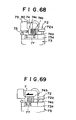
- Such an embodiment is shown in Figures 68 to 72.
- the lock member is provided with a finger board portion which is slid back and forth on a side face of the lighter to move the lock member between the locking position and the releasing position, and at the same time, the lock member is connected to a cap which can be opened and closed, thereby providing higher safety.
- the lock member is connected to the cap so that the cap is positioned above the fuel nozzle and prevents fuel from burning when the lock member is in the locking position and is moved to a retracted position where it permits fuel to burn in response to movement of the lock member to the releasing position.
- Figure 68 shows the state where the lock member is in the locking position and the cap is positioned above the fuel nozzle
- Figure 69 shows the state where the lock member is in the releasing position with the cap in the retracted position
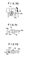
- Figure 70 shows the state where the ignition lever is depressed
- Figure 71 shows the position of the recess of the ignition lever relative to the protrusion of the lock member upon initiation of depression of the ignition lever
- Figure 72 shows the position of the recess of the ignition lever relative to the protrusion of the lock member in the state where the ignition lever has been depressed.
- the lock member 74 is movable back and forth on a side face of the intermediate casing 73a of the lighter body 73 and is connected to a cap 79 which can be opened and closed as shown in Figure 68.
- the cap 79 is moved together with the lock member 74 along a windshield 80 to open and close the upper opening of the windshield 80 between a position above the above the fuel nozzle (shown in Figure 68) where it prevents fuel from burning and a retracted position (shown in Figures 69 70) where it permits fuel to burn.
- the lock member 74 is integrally connected to the cap 79 and is provided with a pin 74c which is slidably engaged with an elongated hole 75 formed on the side face of the intermediate casing 73a.
- the finger board portion 74b of the lock member 74 is movable back and forth on the side face of the intermediate casing 73a.
- the lock member 74 has an abutment portion 74a which extends below the depressing portion 72a of the ignition lever 72, and when the lighter is not used, the lock member 74 is in the locking position where the abutment portion 74a is positioned below the depressing portion 72a of the ignition lever 72 and prevents depression of the ignition lever 72. In this state, the lighter cannot be ignited and inadvertent ignition of the lighter is prevented.
- the pin 74c of the lock member 74 is engaged with an engagement cutaway portion 72c which is formed on the lower surface of an arm portion 72b of the ignition lever 72 which is on the side of a column 76 opposite to the side of the depressing portion 72a as shown in Figure 71, the column 76 being for supporting depression of the ignition lever 72.
- the lock member 74 is held in the releasing position by the engagement between the pin 74c and the cutaway portion 72c.
- the pin 74c of the lock member 74 is disengaged from the cutaway portion 72c of the ignition lever 72 and the lock member 74 moves rightward under the force of the spring 77 as shown in Figure 72.
- the lock member 74 is released from the releasing position and tends to return to the locking position.
- the abutment portion 74a of the lock member 74 abuts against the depressing portion 72a of the ignition lever 72, the lock member 74 is temporarily held in a position slightly deviated toward the locking position from releasing position.
- the lock member 74 prevents depression of the ignition lever 72 thereby preventing inadvertent ignition of the lighter while the lighter is not used, and the lock member 74 is automatically returned to the locking position after it is moved to the releasing position and the lighter is ignited.
- the lock mechanism is automatically restored without operation after it is once released and the lighter is ignited.
- the lock mechanism is arranged to be released by movement of the lock member along a linear path to the releasing position and the lock member is automatically held in the releasing position, the user can actuate the ignition lever with either the finger which has been used to release the lock mechanism or any finger else independently from action of releasing the lock mechanism.
- a gas lighter with a safety device which is excellent both in ease of handling and in safety function and which can be operated steadily without depending on the person who uses it.
- the pin 74c doubles a means which is engaged with the elongated hole 75 and guides slide of the lock member 74 with a means which is engaged with the cutaway portion 72c of the ignition lever 72 and holes the lock member 74 in the releasing position, the two means may be separately formed.
- the ignition mechanism need not be limited to the flint type but may be of any type, e.g., a piezoelectric type or an electronic type.
Landscapes
- Engineering & Computer Science (AREA)
- Chemical & Material Sciences (AREA)
- Combustion & Propulsion (AREA)
- Mechanical Engineering (AREA)
- General Engineering & Computer Science (AREA)
- Lighters Containing Fuel (AREA)
Applications Claiming Priority (8)
| Application Number | Priority Date | Filing Date | Title |
|---|---|---|---|
| JP130580/90 | 1990-05-21 | ||
| JP104222/90 | 1990-10-03 | ||
| JP10422290 | 1990-10-03 | ||
| JP13058090 | 1990-11-30 | ||
| JP58291 | 1991-01-11 | ||
| JP582/91 | 1991-01-11 | ||
| JP251396/91 | 1991-09-30 | ||
| JP3251396A JPH04363515A (ja) | 1990-10-03 | 1991-09-30 | 安全装置付ガスライター |
Publications (3)
| Publication Number | Publication Date |
|---|---|
| EP0479318A2 true EP0479318A2 (de) | 1992-04-08 |
| EP0479318A3 EP0479318A3 (en) | 1993-02-24 |
| EP0479318B1 EP0479318B1 (de) | 1995-07-05 |
Family
ID=27453208
Family Applications (1)
| Application Number | Title | Priority Date | Filing Date |
|---|---|---|---|
| EP91116991A Expired - Lifetime EP0479318B1 (de) | 1990-10-03 | 1991-10-04 | Gasfeuerzeug mit Sicherheitsvorrichtung |
Country Status (9)
| Country | Link |
|---|---|
| US (1) | US5186618A (de) |
| EP (1) | EP0479318B1 (de) |
| JP (1) | JPH04363515A (de) |
| KR (1) | KR960002800B1 (de) |
| BR (1) | BR9105913A (de) |
| CA (1) | CA2052701C (de) |
| DE (1) | DE69111012T2 (de) |
| ES (1) | ES2073639T3 (de) |
| WO (1) | WO1992006332A1 (de) |
Cited By (3)
| Publication number | Priority date | Publication date | Assignee | Title |
|---|---|---|---|---|
| EP0682211A1 (de) * | 1994-04-08 | 1995-11-15 | POLYCITY INDUSTRIAL Ltd. | Feuerzeug mit Schiebesicherheitsverschluss |
| US6102689A (en) * | 1998-09-29 | 2000-08-15 | Man; Aman Chung Kai | Push button safety lighter |
| EP2026005A1 (de) * | 2007-08-15 | 2009-02-18 | Shao-Shun Hsu | Hebelartiger Sicherheitszünder |
Families Citing this family (18)
| Publication number | Priority date | Publication date | Assignee | Title |
|---|---|---|---|---|
| JP2731884B2 (ja) * | 1992-06-12 | 1998-03-25 | 株式会社東海 | 安全装置付ガスライター |
| FR2705762B1 (fr) * | 1993-05-28 | 1995-08-18 | Hameur Cie | Sécurité de briquet. |
| CN1062105C (zh) * | 1993-08-02 | 2001-02-14 | 松下电器产业株式会社 | 电话手机及其控制方法 |
| US5364261A (en) * | 1993-10-29 | 1994-11-15 | Huang Yiang F | Safety device for a lighter |
| JP2784145B2 (ja) * | 1994-03-03 | 1998-08-06 | 株式会社東海 | 安全装置付ガスライター |
| US5462432A (en) * | 1994-06-17 | 1995-10-31 | Kim; Jin K. | Gas lighter with ignition safety device |
| US5451159A (en) * | 1994-07-14 | 1995-09-19 | Kim; Jin K. | Gas lighter with safety device to prevent release of gas |
| US5494436A (en) * | 1995-02-17 | 1996-02-27 | Hwang; Ing F. | Gas lighter with a safety knob |
| US5584683A (en) * | 1996-03-05 | 1996-12-17 | Polycity Industrial Limited | Safety lighter with striker wheel stopper |
| US5788476A (en) * | 1996-04-30 | 1998-08-04 | Polycity Industrial Ltd | Childproof piezoelectric lighter with sliding mechanism |
| US5846069A (en) * | 1996-08-20 | 1998-12-08 | Polycity Industrial Limited | Safety lighter with wheel hood |
| US6332771B1 (en) * | 1997-01-22 | 2001-12-25 | Bic Corporation | Utility lighter |
| US6527546B1 (en) * | 1997-01-22 | 2003-03-04 | Bic Corporation | Utility lighter |
| US6382960B1 (en) | 1998-10-15 | 2002-05-07 | B I C Corporation | Child resistant lighter |
| US6206689B1 (en) | 1998-10-15 | 2001-03-27 | Bic Corporation | Child resistant lighter |
| US6533576B1 (en) | 1999-03-03 | 2003-03-18 | Polycity Enterprise Limited | Lighter with child resistant actuating lever |
| US8653942B2 (en) | 2008-08-20 | 2014-02-18 | John Gibson Enterprises, Inc. | Portable biometric lighter |
| US10502419B2 (en) | 2017-09-12 | 2019-12-10 | John Gibson Enterprises, Inc. | Portable biometric lighter |
Family Cites Families (17)
| Publication number | Priority date | Publication date | Assignee | Title |
|---|---|---|---|---|
| US3898031A (en) * | 1974-05-17 | 1975-08-05 | Richard Rusakowicz | Gas fueled safety lighter |
| JPS5632749Y2 (de) * | 1976-11-29 | 1981-08-04 | ||
| JPS6280244A (ja) * | 1985-10-02 | 1987-04-13 | Chuetsu Gokin Chuko Kk | 耐摩耗性黄銅合金 |
| JPH0629856B2 (ja) * | 1986-01-31 | 1994-04-20 | ザ ダウ ケミカル カンパニ− | 繊維−光学プロ−ブ |
| JPS63142562A (ja) * | 1986-12-05 | 1988-06-14 | Hitachi Ltd | カセツト着脱装置 |
| JPH045891Y2 (de) * | 1987-03-09 | 1992-02-19 | ||
| JPH0335975Y2 (de) * | 1987-05-20 | 1991-07-30 | ||
| EP0312627B1 (de) * | 1987-10-21 | 1990-11-28 | Tokai Corporation | Gasfeuerzeug mit Sicherheitsverschluss |
| JPH01178456A (ja) * | 1988-01-06 | 1989-07-14 | Nec Corp | 段付アーマチュアアッセンブリ |
| US4832596A (en) * | 1988-04-15 | 1989-05-23 | Morris Sr Glenn H | Child resistant cigarette lighter |
| JPH053897Y2 (de) * | 1988-06-07 | 1993-01-29 | ||
| WO1990000239A1 (fr) * | 1988-07-01 | 1990-01-11 | Sibjet S.A. | Briquet de securite |
| US5002482B1 (en) * | 1988-09-02 | 2000-02-29 | Bic Corp | Selectively actuatable lighter |
| FR2645626B1 (fr) * | 1989-04-07 | 1994-06-03 | Swedish Match Consumer Product | Briquet a gaz |
| ES2016143A6 (es) * | 1989-06-19 | 1990-10-16 | Laforest Sa | Mecanismo de seguridad para encendedores. |
| US5092764A (en) * | 1990-07-11 | 1992-03-03 | Bic Corporation | Selectively actuatable lighter with locking valve cap |
| JP2509047Y2 (ja) * | 1990-10-22 | 1996-08-28 | タイ メリー カンパニー リミテット | ライタ― |
-
1991
- 1991-09-30 JP JP3251396A patent/JPH04363515A/ja not_active Withdrawn
- 1991-10-02 US US07/770,111 patent/US5186618A/en not_active Expired - Fee Related
- 1991-10-03 KR KR1019920701246A patent/KR960002800B1/ko not_active Expired - Fee Related
- 1991-10-03 CA CA002052701A patent/CA2052701C/en not_active Expired - Fee Related
- 1991-10-03 WO PCT/JP1991/001329 patent/WO1992006332A1/ja not_active Ceased
- 1991-10-03 BR BR919105913A patent/BR9105913A/pt not_active IP Right Cessation
- 1991-10-04 ES ES91116991T patent/ES2073639T3/es not_active Expired - Lifetime
- 1991-10-04 DE DE69111012T patent/DE69111012T2/de not_active Expired - Fee Related
- 1991-10-04 EP EP91116991A patent/EP0479318B1/de not_active Expired - Lifetime
Cited By (3)
| Publication number | Priority date | Publication date | Assignee | Title |
|---|---|---|---|---|
| EP0682211A1 (de) * | 1994-04-08 | 1995-11-15 | POLYCITY INDUSTRIAL Ltd. | Feuerzeug mit Schiebesicherheitsverschluss |
| US6102689A (en) * | 1998-09-29 | 2000-08-15 | Man; Aman Chung Kai | Push button safety lighter |
| EP2026005A1 (de) * | 2007-08-15 | 2009-02-18 | Shao-Shun Hsu | Hebelartiger Sicherheitszünder |
Also Published As
| Publication number | Publication date |
|---|---|
| KR960002800B1 (ko) | 1996-02-26 |
| EP0479318B1 (de) | 1995-07-05 |
| DE69111012D1 (de) | 1995-08-10 |
| CA2052701C (en) | 1996-01-16 |
| US5186618A (en) | 1993-02-16 |
| WO1992006332A1 (fr) | 1992-04-16 |
| BR9105913A (pt) | 1992-11-10 |
| DE69111012T2 (de) | 1995-11-30 |
| ES2073639T3 (es) | 1995-08-16 |
| CA2052701A1 (en) | 1992-04-04 |
| JPH04363515A (ja) | 1992-12-16 |
| EP0479318A3 (en) | 1993-02-24 |
Similar Documents
| Publication | Publication Date | Title |
|---|---|---|
| CA2052701C (en) | Gas lighter with safety device | |
| EP0488158B1 (de) | Sicherheitsvorrichtung für piezoelektrisches Feuerzeug | |
| JP2784977B2 (ja) | 安全装置付ガスライター | |
| US6135761A (en) | Safety arrangement for piezoelectric lighter | |
| EP0546373B1 (de) | Gasfeuerzeug mit Sicherheitsvorrichtung | |
| US6217313B1 (en) | Childproof barbecue lighter | |
| US6095796A (en) | Double-button piezoelectric child-resistant cigarette lighter | |
| AU675994B2 (en) | Selectively actuatable lighter | |
| US6682341B2 (en) | Child resistant actuator for piezoelectric lighter | |
| AU675993B2 (en) | Selectively actuatable lighter | |
| US6638056B2 (en) | Piezoelectric lighter with safety arrangement | |
| JP3523451B2 (ja) | ガスライター | |
| US7052272B2 (en) | Multi-button piezoelectric child-resistant cigarette lighter | |
| US6422860B2 (en) | Double-button piezoelectric child-resistant cigarette lighter | |
| JPH0658538A (ja) | 安全装置付ガスライター | |
| US6142766A (en) | Safety lighter | |
| US6299434B1 (en) | Double-button piezoelectric child-resistant cigarette lighter | |
| CA2147651C (en) | Selectively actuatable lighter | |
| JP2556593Y2 (ja) | フリント式ライターの操作ロック機構 | |
| HK1011071B (en) | Selectively actuatable lighter |
Legal Events
| Date | Code | Title | Description |
|---|---|---|---|
| PUAI | Public reference made under article 153(3) epc to a published international application that has entered the european phase |
Free format text: ORIGINAL CODE: 0009012 |
|
| 17P | Request for examination filed |
Effective date: 19911004 |
|
| AK | Designated contracting states |
Kind code of ref document: A2 Designated state(s): DE ES FR |
|
| PUAL | Search report despatched |
Free format text: ORIGINAL CODE: 0009013 |
|
| AK | Designated contracting states |
Kind code of ref document: A3 Designated state(s): DE ES FR |
|
| 17Q | First examination report despatched |
Effective date: 19940204 |
|
| RAP1 | Party data changed (applicant data changed or rights of an application transferred) |
Owner name: TOKAI CORPORATION |
|
| GRAA | (expected) grant |
Free format text: ORIGINAL CODE: 0009210 |
|
| AK | Designated contracting states |
Kind code of ref document: B1 Designated state(s): DE ES FR |
|
| REF | Corresponds to: |
Ref document number: 69111012 Country of ref document: DE Date of ref document: 19950810 |
|
| REG | Reference to a national code |
Ref country code: ES Ref legal event code: FG2A Ref document number: 2073639 Country of ref document: ES Kind code of ref document: T3 |
|
| ET | Fr: translation filed | ||
| PLBE | No opposition filed within time limit |
Free format text: ORIGINAL CODE: 0009261 |
|
| STAA | Information on the status of an ep patent application or granted ep patent |
Free format text: STATUS: NO OPPOSITION FILED WITHIN TIME LIMIT |
|
| 26N | No opposition filed | ||
| PGFP | Annual fee paid to national office [announced via postgrant information from national office to epo] |
Ref country code: FR Payment date: 20000919 Year of fee payment: 10 |
|
| PGFP | Annual fee paid to national office [announced via postgrant information from national office to epo] |
Ref country code: DE Payment date: 20000920 Year of fee payment: 10 |
|
| PGFP | Annual fee paid to national office [announced via postgrant information from national office to epo] |
Ref country code: ES Payment date: 20001107 Year of fee payment: 10 |
|
| PG25 | Lapsed in a contracting state [announced via postgrant information from national office to epo] |
Ref country code: ES Free format text: LAPSE BECAUSE OF NON-PAYMENT OF DUE FEES Effective date: 20011005 |
|
| PG25 | Lapsed in a contracting state [announced via postgrant information from national office to epo] |
Ref country code: FR Free format text: LAPSE BECAUSE OF NON-PAYMENT OF DUE FEES Effective date: 20020628 |
|
| PG25 | Lapsed in a contracting state [announced via postgrant information from national office to epo] |
Ref country code: DE Free format text: LAPSE BECAUSE OF NON-PAYMENT OF DUE FEES Effective date: 20020702 |
|
| REG | Reference to a national code |
Ref country code: FR Ref legal event code: ST |
|
| REG | Reference to a national code |
Ref country code: ES Ref legal event code: FD2A Effective date: 20021113 |