EP0478958A2 - Capteur capacitif pour mesurer un film de carburant sur une surface - Google Patents
Capteur capacitif pour mesurer un film de carburant sur une surface Download PDFInfo
- Publication number
- EP0478958A2 EP0478958A2 EP91114510A EP91114510A EP0478958A2 EP 0478958 A2 EP0478958 A2 EP 0478958A2 EP 91114510 A EP91114510 A EP 91114510A EP 91114510 A EP91114510 A EP 91114510A EP 0478958 A2 EP0478958 A2 EP 0478958A2
- Authority
- EP
- European Patent Office
- Prior art keywords
- capacitive sensor
- sensor according
- electrodes
- electrode
- carrier
- Prior art date
- Legal status (The legal status is an assumption and is not a legal conclusion. Google has not performed a legal analysis and makes no representation as to the accuracy of the status listed.)
- Granted
Links
Images


Classifications
-
- G—PHYSICS
- G01—MEASURING; TESTING
- G01D—MEASURING NOT SPECIALLY ADAPTED FOR A SPECIFIC VARIABLE; ARRANGEMENTS FOR MEASURING TWO OR MORE VARIABLES NOT COVERED IN A SINGLE OTHER SUBCLASS; TARIFF METERING APPARATUS; MEASURING OR TESTING NOT OTHERWISE PROVIDED FOR
- G01D5/00—Mechanical means for transferring the output of a sensing member; Means for converting the output of a sensing member to another variable where the form or nature of the sensing member does not constrain the means for converting; Transducers not specially adapted for a specific variable
- G01D5/12—Mechanical means for transferring the output of a sensing member; Means for converting the output of a sensing member to another variable where the form or nature of the sensing member does not constrain the means for converting; Transducers not specially adapted for a specific variable using electric or magnetic means
- G01D5/14—Mechanical means for transferring the output of a sensing member; Means for converting the output of a sensing member to another variable where the form or nature of the sensing member does not constrain the means for converting; Transducers not specially adapted for a specific variable using electric or magnetic means influencing the magnitude of a current or voltage
- G01D5/24—Mechanical means for transferring the output of a sensing member; Means for converting the output of a sensing member to another variable where the form or nature of the sensing member does not constrain the means for converting; Transducers not specially adapted for a specific variable using electric or magnetic means influencing the magnitude of a current or voltage by varying capacitance
- G01D5/2405—Mechanical means for transferring the output of a sensing member; Means for converting the output of a sensing member to another variable where the form or nature of the sensing member does not constrain the means for converting; Transducers not specially adapted for a specific variable using electric or magnetic means influencing the magnitude of a current or voltage by varying capacitance by varying dielectric
-
- G—PHYSICS
- G01—MEASURING; TESTING
- G01B—MEASURING LENGTH, THICKNESS OR SIMILAR LINEAR DIMENSIONS; MEASURING ANGLES; MEASURING AREAS; MEASURING IRREGULARITIES OF SURFACES OR CONTOURS
- G01B7/00—Measuring arrangements characterised by the use of electric or magnetic techniques
- G01B7/02—Measuring arrangements characterised by the use of electric or magnetic techniques for measuring length, width or thickness
- G01B7/06—Measuring arrangements characterised by the use of electric or magnetic techniques for measuring length, width or thickness for measuring thickness
- G01B7/08—Measuring arrangements characterised by the use of electric or magnetic techniques for measuring length, width or thickness for measuring thickness using capacitive means
Definitions
- the invention is based on a capacitive sensor according to the preamble of the main claim.
- a capacitive measuring method for determining the thickness of liquid films is known from the magazine ATM (Archive for Technical Measurement, Sheet V, 1124-19, November 1972, pages 201 to 204).
- a capacitive sensor is used, the electrodes of which are comb-shaped and toothed. These capacitors form a lateral capacitor, the capacitance of which changes when the electrodes and the interspaces are wetted with a liquid. Since the change in capacitance due to wetting depends very much on the size of the capacitance, several capacitive elements are interconnected.
- the sensor according to the invention with the characterizing features of the main claim has the advantage that the relative change in capacitance when the electrodes are wetted is large, since the additional ground electrode reduces the capacitive coupling between the electrodes via the back of the sensor to a minimum, so that the greatest capacity contribution is delivered via the gap between the electrodes on the top of the sensor. Furthermore, the defined mass of the sensor on the rear side shields the outside, so that the influence of electrical interference fields against ground is dissipated and undefined ground surfaces near the rear side do not influence the sensor characteristic.
- the continuous ground electrode particularly advantageously provides good shielding against electrical interference fields.
- the large ground area is very low-resistance, so that the voltage offset on the ground electrode is low.
- Another advantage is that the effect of parasitic capacitances on the back of the sensor is largely avoided.
- the laterally arranged electrodes and the ground electrode are applied to the surfaces of a plastic film.
- Plastic films are good insulators, are easy to form and can easily be provided with conductive layers.
- both the measuring range and the measuring sensitivity can be selected by the arrangement and design of the electrodes. This allows the sensor to be easily adapted to the requirements of the measurement object.
- the arrangement can be constructed very easily by supplying the capacitor elements together with the same generator. Only a few supply lines are advantageously required, since the corresponding electrodes of the sensor elements are connected in parallel. In particular, it is advantageous that by supplying the electrodes with a triangular or sinusoidal alternating voltage, no high current peaks occur when the capacitors are recharged.
- the individual capacitor elements are arranged in close proximity without the measurement signals crosstalk. This means that the sensor can also be used in tight spaces.
- Another advantage is that one lateral electrode is connected to ground potential. As a result, no potential differences form between this electrode and the third electrode. The measurement signal can therefore also be carried over longer supply lines.
- FIG. 1 shows a sensor in plan view
- FIG. 2 shows a capacitor element
- FIG. 3 shows a sectional view
- FIG. 4 shows a second exemplary embodiment
- FIG. 5 shows a corresponding capacitor element
- FIG. 6 shows a sectional view
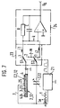
- FIG. 7 shows an evaluation circuit.
- a first embodiment is shown in Figure 1.
- a carrier substrate 5 which is designed as an insulator and consists, for example, of a plastic such as polyimide, laterally formed capacitor elements 2 are arranged in rows and columns.
- the carrier substrate can have a flexible material.
- each capacitor element has a first circular electrode 3, which is surrounded in a ring at a distance d by a second electrode 4.
- the second electrode has a gap through which a connecting line 7 is led to the first electrode 3.
- the electrodes consist of an electrically conductive material, for example of copper, aluminum, gold, coal or silver alloys.
- the electrodes 3, 4 are applied, for example as laminates.
- the first electrode 3 of a capacitor element is connected to a common line 8 via the connection 7.
- the common line 8 is shielded by two parallel ground fields 9, which are also applied to the carrier 5.
- the back of the carrier 5 is provided with a continuous conductive laminate.
- the structure is shown in the sectional view of Figure 3.
- the ground electrode 6 can be made of the same material as the capacitor electrodes 3, 4.
- the carrier 5 can be designed as a flexible film that is easily adaptable, in particular, to curved surfaces.
- the sensor 1 has capacitor elements 2 in an enlarged representation, which are arranged relatively closely in rows and columns.
- the individual elements are supplied with AC voltage via the common line 8, which leads to the first electrode 3.
- the second electrode 4 is separate Lead to the terminal block 10. If the rear ground electrode is counted, then n + 2 lines are required for n capacitor elements. The number of elements required can be selected as required. If, for example, the sensor is used to measure the fuel film height in the intake pipe of an internal combustion engine, then it is particularly advantageous if the second electrode 4 is led out separately via a measuring line, since the wall film height can be very different at the individual locations in the intake pipe. This gives a large number of measuring points that can be detected with relatively few lines.
- FIGS. 4 to 6 A second exemplary embodiment of the invention is shown in FIGS. 4 to 6.
- the sensor 11 has capacitor elements 12, which have comb-shaped electrodes 13, 14 and are toothed, so that the capacitance of a capacitor element 12 is formed by the sum of the capacitances of the opposing teeth or strips.
- the encoder elements 12 have the same arrangement as in the first embodiment.
- the electrodes 13 are controlled by a common supply line 8. As in the first exemplary embodiment, the supply line 8 is shielded via partially parallel ground lines 9. As in the first exemplary embodiment, the lines 9 are electrically connected to the ground electrode 6 on the back of the carrier 5.
- the second electrode 14 is led out to the terminal block 10 via a separate measuring line.
- FIG. 6 shows a section through a capacitor element 12, in which the arrangement of the electrodes 13, 14 and the ground electrode 16 on both sides of the carrier 15 is shown in particular.
- the mode of operation of these exemplary embodiments is described below.
- the sensor is particularly well suited for measuring the wall film height of a fuel in the intake pipe of an internal combustion engine, for example gasoline or diesel.
- the sensor is installed in the inner tube of the intake manifold of the internal combustion engine at the point to be measured.
- the measurement signals are brought out via the terminal strip 10 and can be evaluated by an evaluation circuit, as is shown, for example, in FIG.
- the electrodes 3; 13 is excited with a triangular or sinusoidal AC voltage u e with a frequency f of, for example, 200 kHz and a voltage swing ⁇ u e between the extreme values of, for example, 10 V.
- the electrodes 4; 14 are each connected via the changeover contact S1 of the electronic switch 23, either to the inverting input k of the feedback operational amplifier or to the ground m.
- the switches S1 and S2 change their switch position (1 or 2) in a phase-locked manner with the AC voltage u e when the AC voltage u e reaches its upper or lower extreme value.
- the node k Because of the feedback of the operational amplifier, the node k always has ground potential. When the two switches are switched over, the potential of the switch-side connections C2; 12 and C22 therefore advantageously does not change.
- the switch ensures that the capacitors C2, 12 and C22 are charged differently depending on the switch position from different charge sources: in switch position 1 from node k, in switch position 2 from node m.
- the parasitic capacitance that emerges from the rear third electrode 6; 16 of the sensor 1; 11 and the electrode 4; 14 is formed, and the parasitic capacitance of the connecting line to the electrode 4; 14, however, advantageously make no contribution to the charge exchange due to the lack of potential fluctuation.
- the third electrode on the rear can thus advantageously be used as a shield against rear crosstalk and for shielding against external interference radiation, so that the sensitivity of the sensor 1; 11 is increased.
- Signals from sensors with adjacent connecting lines advantageously do not show mutual capacitive crosstalk because of the negligibly small fluctuations in potential. This makes it possible to lay many parallel sensor connection lines in a very small space, the connection lines being relatively long and thus allowing the electronic circuit to be arranged relatively far away.
- the substrate can be selected from other points of view such as flexibility.
Landscapes
- Physics & Mathematics (AREA)
- General Physics & Mathematics (AREA)
- Investigating Or Analyzing Materials By The Use Of Electric Means (AREA)
- Measurement Of Length, Angles, Or The Like Using Electric Or Magnetic Means (AREA)
Applications Claiming Priority (2)
| Application Number | Priority Date | Filing Date | Title |
|---|---|---|---|
| DE4031210 | 1990-10-04 | ||
| DE4031210A DE4031210A1 (de) | 1990-10-04 | 1990-10-04 | Kapazitiver sensor zur messung eines kraftstoffwandfilms |
Publications (3)
| Publication Number | Publication Date |
|---|---|
| EP0478958A2 true EP0478958A2 (fr) | 1992-04-08 |
| EP0478958A3 EP0478958A3 (fr) | 1994-01-19 |
| EP0478958B1 EP0478958B1 (fr) | 1995-11-29 |
Family
ID=6415457
Family Applications (1)
| Application Number | Title | Priority Date | Filing Date |
|---|---|---|---|
| EP91114510A Expired - Lifetime EP0478958B1 (fr) | 1990-10-04 | 1991-08-29 | Capteur capacitif pour mesurer un film de carburant sur une surface |
Country Status (4)
| Country | Link |
|---|---|
| US (1) | US5175505A (fr) |
| EP (1) | EP0478958B1 (fr) |
| JP (1) | JPH04273002A (fr) |
| DE (2) | DE4031210A1 (fr) |
Cited By (1)
| Publication number | Priority date | Publication date | Assignee | Title |
|---|---|---|---|---|
| US7246883B2 (en) | 1997-07-15 | 2007-07-24 | Silverbrook Research Pty Ltd | Motion transmitting structure for a nozzle arrangement of a printhead chip for an inkjet printhead |
Families Citing this family (27)
| Publication number | Priority date | Publication date | Assignee | Title |
|---|---|---|---|---|
| EP0544548B1 (fr) * | 1991-11-28 | 1998-11-11 | Ngk Spark Plug Co., Ltd | Testeur de potentiel de bougie d'allumage dans un moteur à combustion interne |
| DE4447867B4 (de) * | 1993-11-30 | 2005-09-08 | Honda Giken Kogyo K.K. | Kraftstoffeinspritzmengen-Steuersystem für Verbrennungsmotoren und dabei benutzte Bestimmungseinrichtung für die Ansaugkanal-Wandtemperatur |
| US5532605A (en) * | 1994-10-27 | 1996-07-02 | Agr International, Inc. | Container inspection apparatus having diameter measuring means and associated method |
| GB9519006D0 (en) * | 1995-09-16 | 1995-11-15 | Rolls Royce & Ass | Capacitance probe |
| US5955887A (en) * | 1995-12-22 | 1999-09-21 | The B. F. Goodrich Company | Impedance type ice detector |
| US6194903B1 (en) * | 1996-01-21 | 2001-02-27 | I F M Electronic Gmbh | Circuit for acquisition of the capacitance or capacitance change of a capacitive circuit element or component |
| US5765434A (en) * | 1996-07-18 | 1998-06-16 | Scepter Scientific, Inc. | Capacitive water height gauge and method |
| WO1998057132A1 (fr) * | 1997-06-12 | 1998-12-17 | Matulek Andrew M | Temoin capacitif de niveau de liquide |
| US6389330B1 (en) | 1997-12-18 | 2002-05-14 | Reuter-Stokes, Inc. | Combustion diagnostics method and system |
| US6227046B1 (en) * | 1998-09-21 | 2001-05-08 | The United States Of America As Represented By The Administrator Of The National Aeronautics And Space Administration | System for measuring capacitance |
| US6504386B1 (en) * | 1999-09-28 | 2003-01-07 | The Ohio State University | Liquid dielectric capacitor for film thickness mapping, measurement methods using same |
| JP2004511078A (ja) * | 2000-10-13 | 2004-04-08 | フラット ホワイト ライティング ピーティーワイ リミテッド | 照明システム |
| EP1677084A1 (fr) * | 2004-12-22 | 2006-07-05 | Roxer Industries S.A. | Capteur de niveau d'un liquide et méthode d'estimation. |
| US20080229820A1 (en) * | 2005-10-26 | 2008-09-25 | Volodia Naydenov | Capacitive Gauge |
| FR2892509B1 (fr) * | 2005-10-26 | 2007-12-21 | Inergy Automotive Systems Res | Jauge capacitive pour reservoir a carburant |
| GB2456937B (en) | 2006-10-24 | 2011-07-13 | Bradley Fixtures Corp | Capacitive sensing for washroom fixture |
| CN101349537B (zh) * | 2008-09-13 | 2010-06-16 | 陈立峰 | 金属管筒厚度及内壁粗糙度的检测成像方法及其装置 |
| US8866624B2 (en) * | 2008-12-31 | 2014-10-21 | Kimberly-Clark Worldwide, Inc. | Conductor-less detection system for an absorbent article |
| GB2481002B (en) * | 2010-06-04 | 2015-01-14 | Plastic Logic Ltd | Determining layer thickness |
| US8572840B2 (en) * | 2010-09-30 | 2013-11-05 | International Business Machines Corporation | Method of attaching an electronic module power supply |
| US9163972B2 (en) | 2011-06-16 | 2015-10-20 | Delta Faucet Company | Apparatus and method for reducing cross-talk between capacitive sensors |
| US8973612B2 (en) | 2011-06-16 | 2015-03-10 | Masco Corporation Of Indiana | Capacitive sensing electronic faucet including differential measurements |
| WO2016138331A1 (fr) | 2015-02-27 | 2016-09-01 | Kimberly-Clark Worldwide, Inc. | Système d'évaluation des fuites d'un article absorbant |
| CN108306499A (zh) * | 2017-01-11 | 2018-07-20 | 北京普源精电科技有限公司 | 降低精密仪器噪声干扰的方法及装置 |
| WO2018186842A1 (fr) | 2017-04-05 | 2018-10-11 | Kimberly-Clark Worldwide, Inc. | Vêtement pour détecter des fuites d'un article absorbant et procédés de détection des fuites d'un article absorbant l'utilisant |
| US11768302B2 (en) * | 2020-10-26 | 2023-09-26 | The Texas A&M University System | Technologies for multifunction sensor devices and microcontroller-based interface module |
| CN113324467B (zh) * | 2021-05-27 | 2023-03-31 | 贵州电网有限责任公司 | 基于冰介质电容效应的导线等值覆冰厚度监测装置及方法 |
Citations (1)
| Publication number | Priority date | Publication date | Assignee | Title |
|---|---|---|---|---|
| DE2150928A1 (de) * | 1970-10-15 | 1972-05-31 | Texcontrol | Kapazitiver Messkopf |
Family Cites Families (3)
| Publication number | Priority date | Publication date | Assignee | Title |
|---|---|---|---|---|
| US3739265A (en) * | 1970-09-09 | 1973-06-12 | J Skildum | Test instrument and method for isolating and measuring the capacitance due to a particular functional group in a liquid |
| FR2136999B1 (fr) * | 1971-05-11 | 1973-05-11 | Radiotechnique Compelec | |
| US4423371A (en) * | 1981-09-03 | 1983-12-27 | Massachusetts Institute Of Technology | Methods and apparatus for microdielectrometry |
-
1990
- 1990-10-04 DE DE4031210A patent/DE4031210A1/de not_active Ceased
-
1991
- 1991-08-29 EP EP91114510A patent/EP0478958B1/fr not_active Expired - Lifetime
- 1991-08-29 DE DE59106985T patent/DE59106985D1/de not_active Expired - Fee Related
- 1991-09-26 US US07/766,444 patent/US5175505A/en not_active Expired - Fee Related
- 1991-10-03 JP JP3256072A patent/JPH04273002A/ja active Pending
Patent Citations (1)
| Publication number | Priority date | Publication date | Assignee | Title |
|---|---|---|---|---|
| DE2150928A1 (de) * | 1970-10-15 | 1972-05-31 | Texcontrol | Kapazitiver Messkopf |
Non-Patent Citations (1)
| Title |
|---|
| ARCHIV F¨R TECHNISCHES MESSEN + MESSTECHNISCHE PRAXIS, "Ein kapazitives MeŸ- verfahren zur Bestimmung der Dicke von FlÙssigkeits- filmen", Blatt V 1124-19, November 1972, R. OLDENBOURG VERLAG M¨NCHEN, Seiten 201-204 * |
Cited By (1)
| Publication number | Priority date | Publication date | Assignee | Title |
|---|---|---|---|---|
| US7246883B2 (en) | 1997-07-15 | 2007-07-24 | Silverbrook Research Pty Ltd | Motion transmitting structure for a nozzle arrangement of a printhead chip for an inkjet printhead |
Also Published As
| Publication number | Publication date |
|---|---|
| DE4031210A1 (de) | 1992-04-09 |
| EP0478958A3 (fr) | 1994-01-19 |
| EP0478958B1 (fr) | 1995-11-29 |
| JPH04273002A (ja) | 1992-09-29 |
| DE59106985D1 (de) | 1996-01-11 |
| US5175505A (en) | 1992-12-29 |
Similar Documents
| Publication | Publication Date | Title |
|---|---|---|
| EP0478958B1 (fr) | Capteur capacitif pour mesurer un film de carburant sur une surface | |
| DE4031560C2 (de) | Stromsensor mit magnetfeldempfindlichen Bauelementen und Verwendung | |
| EP3472629B1 (fr) | Système de mesure servant à mesurer un courant électrique dans la plage des courants forts | |
| EP0447514B1 (fr) | Circuit de mesure de temperature | |
| DE3007557A1 (de) | Elektrometer-messfuehler | |
| DE19643698C2 (de) | Vorrichtung zur Abschirmung von für kapazitive Messungen verwendeten Leiterbahnen eines Kochfeldes | |
| DE4211944A1 (de) | Hochspannungseinheit mit einer Meßteiler-Widerstandsanordnung | |
| DE2948660A1 (de) | Influenzsondenanordnung und verfahren zu ihrer herstellung | |
| DE2603185C2 (de) | Anordnung zur kapazitiven Messung des Füllstandes eines Behälters | |
| DD93037B1 (de) | Kapazitives weg- und winkelmesssystem | |
| DE3405442C1 (de) | Meßwiderstand | |
| WO1999015906A1 (fr) | Transformateur combine de courant et de tension pour signaux faibles | |
| DE2356440A1 (de) | Einrichtung zur erfassung der zuendspannung | |
| DE10143034A1 (de) | Vorrichtung zum Messen von Störkapazitäten auf einer integrierten Schaltung | |
| DE2938542C2 (de) | Signalzuführungsanordnung für ein Oberflächenwellen-Bauteil | |
| EP1015895B1 (fr) | Diviseur de tension | |
| DE102004038568A1 (de) | Hochspannungserzeugungseinrichtung mit internem Messwiderstand | |
| EP1782080B1 (fr) | Ensemble pour l'alimentation electrique d'un appareil de mesure | |
| AT405884B (de) | Detektor zur messung der elektrolytischen leitfähigkeit | |
| EP0185255B1 (fr) | Procédé pour déterminer la polarité de composants électroniques et dispositif mettant en oeuvre ce procédé | |
| DE7540302U (de) | Ionisationselektrode | |
| DE4219908A1 (de) | Ferromagnetische widerstandseinheit in vollweg-brueckenschaltung | |
| EP0191899B1 (fr) | Capteur pour mesurer des propriétés électriques dans un champ électrique | |
| DE2714142A1 (de) | Einrichtung zur messung eines magnetflusses | |
| EP0724140B1 (fr) | Procédé et dispositif pour l'évaluation des signaux d'un capteur de niveau capacitif |
Legal Events
| Date | Code | Title | Description |
|---|---|---|---|
| PUAI | Public reference made under article 153(3) epc to a published international application that has entered the european phase |
Free format text: ORIGINAL CODE: 0009012 |
|
| AK | Designated contracting states |
Kind code of ref document: A2 Designated state(s): DE FR GB IT SE |
|
| PUAL | Search report despatched |
Free format text: ORIGINAL CODE: 0009013 |
|
| AK | Designated contracting states |
Kind code of ref document: A3 Designated state(s): DE FR GB IT SE |
|
| 17P | Request for examination filed |
Effective date: 19940708 |
|
| 17Q | First examination report despatched |
Effective date: 19940909 |
|
| GRAA | (expected) grant |
Free format text: ORIGINAL CODE: 0009210 |
|
| AK | Designated contracting states |
Kind code of ref document: B1 Designated state(s): DE FR GB IT SE |
|
| REF | Corresponds to: |
Ref document number: 59106985 Country of ref document: DE Date of ref document: 19960111 |
|
| ET | Fr: translation filed | ||
| ITF | It: translation for a ep patent filed |
Owner name: STUDIO JAUMANN |
|
| GBT | Gb: translation of ep patent filed (gb section 77(6)(a)/1977) |
Effective date: 19960217 |
|
| PLBE | No opposition filed within time limit |
Free format text: ORIGINAL CODE: 0009261 |
|
| STAA | Information on the status of an ep patent application or granted ep patent |
Free format text: STATUS: NO OPPOSITION FILED WITHIN TIME LIMIT |
|
| 26N | No opposition filed | ||
| PGFP | Annual fee paid to national office [announced via postgrant information from national office to epo] |
Ref country code: SE Payment date: 19980824 Year of fee payment: 8 |
|
| PGFP | Annual fee paid to national office [announced via postgrant information from national office to epo] |
Ref country code: GB Payment date: 19980825 Year of fee payment: 8 |
|
| PG25 | Lapsed in a contracting state [announced via postgrant information from national office to epo] |
Ref country code: GB Free format text: LAPSE BECAUSE OF NON-PAYMENT OF DUE FEES Effective date: 19990829 |
|
| PG25 | Lapsed in a contracting state [announced via postgrant information from national office to epo] |
Ref country code: SE Free format text: THE PATENT HAS BEEN ANNULLED BY A DECISION OF A NATIONAL AUTHORITY Effective date: 19990830 |
|
| GBPC | Gb: european patent ceased through non-payment of renewal fee |
Effective date: 19990829 |
|
| EUG | Se: european patent has lapsed |
Ref document number: 91114510.0 |
|
| PGFP | Annual fee paid to national office [announced via postgrant information from national office to epo] |
Ref country code: FR Payment date: 20010824 Year of fee payment: 11 |
|
| PGFP | Annual fee paid to national office [announced via postgrant information from national office to epo] |
Ref country code: DE Payment date: 20011025 Year of fee payment: 11 |
|
| PG25 | Lapsed in a contracting state [announced via postgrant information from national office to epo] |
Ref country code: DE Free format text: LAPSE BECAUSE OF NON-PAYMENT OF DUE FEES Effective date: 20030301 |
|
| PG25 | Lapsed in a contracting state [announced via postgrant information from national office to epo] |
Ref country code: FR Free format text: LAPSE BECAUSE OF NON-PAYMENT OF DUE FEES Effective date: 20030430 |
|
| REG | Reference to a national code |
Ref country code: FR Ref legal event code: ST |
|
| PG25 | Lapsed in a contracting state [announced via postgrant information from national office to epo] |
Ref country code: IT Free format text: LAPSE BECAUSE OF NON-PAYMENT OF DUE FEES;WARNING: LAPSES OF ITALIAN PATENTS WITH EFFECTIVE DATE BEFORE 2007 MAY HAVE OCCURRED AT ANY TIME BEFORE 2007. THE CORRECT EFFECTIVE DATE MAY BE DIFFERENT FROM THE ONE RECORDED. Effective date: 20050829 |