EP0478098A2 - Installation de commutation blindée a moyenne tension avec des traversées pour la réalisation une connection externe à la terre - Google Patents
Installation de commutation blindée a moyenne tension avec des traversées pour la réalisation une connection externe à la terre Download PDFInfo
- Publication number
- EP0478098A2 EP0478098A2 EP91250237A EP91250237A EP0478098A2 EP 0478098 A2 EP0478098 A2 EP 0478098A2 EP 91250237 A EP91250237 A EP 91250237A EP 91250237 A EP91250237 A EP 91250237A EP 0478098 A2 EP0478098 A2 EP 0478098A2
- Authority
- EP
- European Patent Office
- Prior art keywords
- bushings
- locking member
- voltage switchgear
- short
- contact
- Prior art date
- Legal status (The legal status is an assumption and is not a legal conclusion. Google has not performed a legal analysis and makes no representation as to the accuracy of the status listed.)
- Granted
Links
- 239000004020 conductor Substances 0.000 claims description 6
- 230000005484 gravity Effects 0.000 claims description 3
- 230000000903 blocking effect Effects 0.000 claims description 2
- 238000012360 testing method Methods 0.000 description 8
- 238000006073 displacement reaction Methods 0.000 description 1
- 238000005538 encapsulation Methods 0.000 description 1
- 230000003993 interaction Effects 0.000 description 1
- 238000000034 method Methods 0.000 description 1
Images

Classifications
-
- H—ELECTRICITY
- H02—GENERATION; CONVERSION OR DISTRIBUTION OF ELECTRIC POWER
- H02B—BOARDS, SUBSTATIONS OR SWITCHING ARRANGEMENTS FOR THE SUPPLY OR DISTRIBUTION OF ELECTRIC POWER
- H02B11/00—Switchgear having carriage withdrawable for isolation
- H02B11/28—Earthing arrangements
Definitions
- the invention relates to a gas-insulated and encapsulated medium-voltage switchgear assembly with an earthing switch and with bushings arranged in a row for establishing an earth connection outside the gas space by means of a detachably arranged connecting rail.
- a switchgear of this type is known from DE-C-34 36 084.
- An angled connecting rail is provided for each of the bushings, which connects an earth terminal attached to the encapsulation to an outer contact surface of the bushing. If necessary, the connecting rails can be detached in order to connect a cable measuring and testing device to the bushings.
- the invention has for its object to ensure after completion of a cable test that all steps required for the proper restoration of the earth connection are carried out inevitably and without errors.
- each bushing has on its outside a contact pin with a cylindrical section which is adapted to a sliding contact unit of a short-circuit bar common to all bushings, which is connected to the earth terminal by a flexible conductor, and that the contact pins are then connected have on the cylindrical portion an end portion for receiving a removal of the shorting bar locking member.
- the earth connection is ensured by the fact that the short-circuit bar is constantly connected to the fixed earth terminal by the flexible conductor; which does not have to be solved when connecting a cable test and measuring device to the bushings.
- the securing member prevents the short-circuit rail from being displaced on the contact bolts of the bushings by arbitrary or other influences.
- each contact pin has an annular groove and the blocking member is designed as a rail with a thickness corresponding to the width of the annular groove and is provided with keyhole-like openings, the further portion of which is the outer diameter of the contact pin and its narrower Section corresponds to the core diameter of the ring groove.
- the locking member can be reliably secured by plugging it onto the contact bolts and subsequent longitudinal displacement.
- the locking member is also U-shaped in cross-section in such a way that the legs rest in the locking position on the short-circuit rail, then reliable support of the short-circuit rail against possible forces is achieved.
- the bushings are arranged on the front of the switchgear and that in the locking member there is a fastening opening for one that hides the bushings Cover is arranged.
- the cover can have a wedge-like inclined surface for actuating a locking panel that enables or blocks the actuation of the earthing switch.
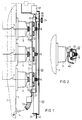
- FIG. 1 schematically shows a part of a medium-voltage load switchgear assembly with bushings arranged on the front for earthing or cable testing in a side view.
- FIG. 2 shows the arrangement according to FIG. 1 in a top view.
- a locking member is shown separately in Figure 3.
- FIG. 4 shows the outer part of a bushing.
- the medium-voltage load switchgear system partially shown in FIG. 1 has a gas-filled container 2, shown broken off, on the front wall 3 of which three bushings 4 are arranged in a vertical row.
- the feed-through conductors are connected to an earthing switch 5, which is only shown as a circuit symbol.
- the earthing switch can be part of a multi-position rotary switch.
- the grounding is made outside the gas space of the container 2 by a device which is described in more detail below.
- each of the bushings 4 has a contact pin 6 which extends horizontally forward.
- the three existing contact bolts 6 are connected to one another by a short-circuit bar 7 (FIGS.
- each of the sliding contact units 10 has a housing body 11 in which the actual contact elements are accommodated.
- the housing body 11 are fastened by means of screws 12 to the short-circuiting rail 7 in such a way that the mutual distance between the sliding contact units 10 can be changed within the scope of a possible tolerance of the distance between the contact bolts 6.
- a flexible conductor 13 is attached, which is connected in a manner not shown to a fixed earth terminal 14. In the example shown, this is also located on the front wall 3 of the container 2.
- each of the contact bolts 6 of the bushings 4 has a section 15 provided for contacting the sliding contact units 10 and an end part 16 with a reduced diameter, which is provided with an annular groove 17.
- a keyhole-like opening 22 is provided for each of the contact bolts 6.
- the openings 22 For the passage of the end part 16 of each contact pin 6, the openings 22 have a correspondingly dimensioned wide area 23, which is followed by a narrower area 24 with a width corresponding to the core diameter of the groove 17.
- the position of the wide section 23 and the narrow section 24 of the opening 22 shown in FIG. 3 corresponds to the position of use.
- the locking member 20 comes under the influence of gravity with the narrow area 24 of the openings 22 into the annular grooves 17 of the contact pin 6. This process can be carried out simply because the legs 21 of the locking member 20th butt against the short-circuit bar 7, thereby ensuring the correct position of the locking member 20 for engaging in the ring grooves 17.
- a cover 30 serves to cover the bushings 4, which can be suspended at its lower end with a pin 31 in a cross member 32 of the switchgear 1. At the upper end there is a swivel bolt 33 which can be actuated by a rotary handle 34 and which interacts with a locking lug 35 of the locking member 20. This results in the position of the cover 30 shown in FIG. 1, in which an inclined surface 36 of the cover 30 has a locking panel 37 raised in the sense of releasing the earthing switch 5. The interaction between the locking panel 37 and the earthing switch 5 is indicated by dashed lines in FIG. 1.
Landscapes
- Engineering & Computer Science (AREA)
- Power Engineering (AREA)
- Gas-Insulated Switchgears (AREA)
- Trip Switchboards (AREA)
- Arc-Extinguishing Devices That Are Switches (AREA)
Applications Claiming Priority (2)
| Application Number | Priority Date | Filing Date | Title |
|---|---|---|---|
| DE4031196 | 1990-09-28 | ||
| DE4031196A DE4031196A1 (de) | 1990-09-28 | 1990-09-28 | Gasisolierte mittelspannungs-schaltanlage mit durchfuehrungen zur herstellung einer aeusseren erdverbindung |
Publications (3)
| Publication Number | Publication Date |
|---|---|
| EP0478098A2 true EP0478098A2 (fr) | 1992-04-01 |
| EP0478098A3 EP0478098A3 (en) | 1993-03-10 |
| EP0478098B1 EP0478098B1 (fr) | 1996-10-23 |
Family
ID=6415449
Family Applications (1)
| Application Number | Title | Priority Date | Filing Date |
|---|---|---|---|
| EP91250237A Expired - Lifetime EP0478098B1 (fr) | 1990-09-28 | 1991-08-28 | Installation de commutation blindée a moyenne tension avec des traversées pour la réalisation une connection externe à la terre |
Country Status (4)
| Country | Link |
|---|---|
| EP (1) | EP0478098B1 (fr) |
| JP (1) | JP3378262B2 (fr) |
| DE (2) | DE4031196A1 (fr) |
| ES (1) | ES2095906T3 (fr) |
Cited By (1)
| Publication number | Priority date | Publication date | Assignee | Title |
|---|---|---|---|---|
| CZ305394B6 (cs) * | 2009-03-30 | 2015-09-02 | Západočeská Universita V Plzni | Uzemňovací zařízení pro přístroje vysokého napětí |
Family Cites Families (4)
| Publication number | Priority date | Publication date | Assignee | Title |
|---|---|---|---|---|
| GB559040A (en) * | 1942-07-22 | 1944-02-01 | Douglas Adrian Muret | Improvements in flame-proof enclosures for electrical or other apparatus |
| US3876846A (en) * | 1972-08-16 | 1975-04-08 | Ite Imperial Corp | Combination ground and test switch apparatus for pressurized-gas-insulated high voltage systems |
| GB2091942B (en) * | 1981-01-24 | 1984-12-19 | Brush Switchgear | Electrical switchgear |
| DE3513499A1 (de) * | 1985-04-16 | 1986-10-16 | Brown, Boveri & Cie Ag, 6800 Mannheim | Lasttrennschalter und schaltanlage mit diesem lasttrennschalter |
-
1990
- 1990-09-28 DE DE4031196A patent/DE4031196A1/de not_active Withdrawn
-
1991
- 1991-08-28 DE DE59108296T patent/DE59108296D1/de not_active Expired - Fee Related
- 1991-08-28 EP EP91250237A patent/EP0478098B1/fr not_active Expired - Lifetime
- 1991-08-28 ES ES91250237T patent/ES2095906T3/es not_active Expired - Lifetime
- 1991-09-27 JP JP27689891A patent/JP3378262B2/ja not_active Expired - Fee Related
Cited By (1)
| Publication number | Priority date | Publication date | Assignee | Title |
|---|---|---|---|---|
| CZ305394B6 (cs) * | 2009-03-30 | 2015-09-02 | Západočeská Universita V Plzni | Uzemňovací zařízení pro přístroje vysokého napětí |
Also Published As
| Publication number | Publication date |
|---|---|
| JP3378262B2 (ja) | 2003-02-17 |
| JPH04261313A (ja) | 1992-09-17 |
| EP0478098B1 (fr) | 1996-10-23 |
| EP0478098A3 (en) | 1993-03-10 |
| DE4031196A1 (de) | 1992-04-02 |
| ES2095906T3 (es) | 1997-03-01 |
| DE59108296D1 (de) | 1996-11-28 |
Similar Documents
| Publication | Publication Date | Title |
|---|---|---|
| EP0270994B1 (fr) | Adaptateur | |
| EP0199891A2 (fr) | Dispositif de connexion pour des installations de commutation à isolation gazeuse | |
| DE3137117A1 (de) | "schraubklemme" | |
| DE2206037A1 (de) | Erdungs- und Prüfeinrichtung für eine metallgekapselte Schaltanlage | |
| EP0478098B1 (fr) | Installation de commutation blindée a moyenne tension avec des traversées pour la réalisation une connection externe à la terre | |
| CH680543A5 (fr) | ||
| EP0484811A1 (fr) | Armoire de commutation électrique pour installations à basse tension | |
| EP0054726B1 (fr) | Dispositif pour la mise à terre des conducteurs d'une installation de commutation blindée et pour le test des cables connectés à ladite installation | |
| DE2423233A1 (de) | Vorrichtung zum elektrischen und mechanischen anschluss von koaxialkabeln | |
| DE2329334A1 (de) | Zentralsteckverbindung | |
| DE29514946U1 (de) | Positioniereinrichtung zum automatischen Stecken einer Buchsenleiste in eine Steckerleiste von geschirmten D-Subverbindungen | |
| DE655584C (de) | Reinigungsvorrichtung fuer elektrische Hochspannungsschaltanlagen | |
| DE616792C (de) | Schaltapparat mit ein oder mehreren abnehmbaren Schaltelementen | |
| DE3412656A1 (de) | Steckvorrichtung und deren anordnung | |
| DE2014806C (de) | Aufnahmevorrichtung für Geräteeinheiten der elektrischen Nachrichtenübertragungstechnik | |
| DE1168990B (de) | Nulleiter-Trennklemmleiste | |
| DE7816003U1 (de) | Haltevorrichtung für Gewindemuttern | |
| WO2018130238A1 (fr) | Dispositif de connexion électrique pour l'alimentation électrique de wagons accouplés d'un véhicule ferroviaire | |
| DE1640826C (de) | Erdungswagen fur mehrphasige trenner lose Hochspannungsschrankanlagen | |
| DE3934069C2 (de) | Unterflurgerätedose mit eingebautem Leitungsschutzschalter | |
| DE2014806B1 (de) | Aufnahmevorrichtung fur Gerateein heiten der elektrischen Nachnchtenuber tragungstechnik | |
| EP0690527A1 (fr) | Dispositif de raccordement | |
| DE2348864C3 (de) | Trennbare Reihenklemme | |
| DE906349C (de) | Elektrischer Mehrfachschalter zum Einschalten von einem oder mehreren beliebig auswaehlbaren Stromkreisen unter Verwendung einer Lochkarte | |
| DE608493C (de) | Schaltanlage mit doppelten Sammelschienen und Kuppelschalter |
Legal Events
| Date | Code | Title | Description |
|---|---|---|---|
| PUAI | Public reference made under article 153(3) epc to a published international application that has entered the european phase |
Free format text: ORIGINAL CODE: 0009012 |
|
| AK | Designated contracting states |
Kind code of ref document: A2 Designated state(s): BE CH DE ES FR GB IT LI NL SE |
|
| PUAL | Search report despatched |
Free format text: ORIGINAL CODE: 0009013 |
|
| AK | Designated contracting states |
Kind code of ref document: A3 Designated state(s): BE CH DE ES FR GB IT LI NL SE |
|
| 17P | Request for examination filed |
Effective date: 19930903 |
|
| 17Q | First examination report despatched |
Effective date: 19950410 |
|
| GRAH | Despatch of communication of intention to grant a patent |
Free format text: ORIGINAL CODE: EPIDOS IGRA |
|
| GRAH | Despatch of communication of intention to grant a patent |
Free format text: ORIGINAL CODE: EPIDOS IGRA |
|
| GRAA | (expected) grant |
Free format text: ORIGINAL CODE: 0009210 |
|
| AK | Designated contracting states |
Kind code of ref document: B1 Designated state(s): BE CH DE ES FR GB IT LI NL SE |
|
| REF | Corresponds to: |
Ref document number: 59108296 Country of ref document: DE Date of ref document: 19961128 |
|
| ITF | It: translation for a ep patent filed | ||
| REG | Reference to a national code |
Ref country code: CH Ref legal event code: NV Representative=s name: SIEMENS SCHWEIZ AG |
|
| GBT | Gb: translation of ep patent filed (gb section 77(6)(a)/1977) |
Effective date: 19970128 |
|
| ET | Fr: translation filed | ||
| REG | Reference to a national code |
Ref country code: ES Ref legal event code: FG2A Ref document number: 2095906 Country of ref document: ES Kind code of ref document: T3 |
|
| PGFP | Annual fee paid to national office [announced via postgrant information from national office to epo] |
Ref country code: GB Payment date: 19970715 Year of fee payment: 7 |
|
| PGFP | Annual fee paid to national office [announced via postgrant information from national office to epo] |
Ref country code: ES Payment date: 19970808 Year of fee payment: 7 |
|
| PGFP | Annual fee paid to national office [announced via postgrant information from national office to epo] |
Ref country code: NL Payment date: 19970821 Year of fee payment: 7 Ref country code: SE Payment date: 19970821 Year of fee payment: 7 |
|
| PGFP | Annual fee paid to national office [announced via postgrant information from national office to epo] |
Ref country code: BE Payment date: 19970822 Year of fee payment: 7 |
|
| PGFP | Annual fee paid to national office [announced via postgrant information from national office to epo] |
Ref country code: FR Payment date: 19970827 Year of fee payment: 7 |
|
| PLBE | No opposition filed within time limit |
Free format text: ORIGINAL CODE: 0009261 |
|
| STAA | Information on the status of an ep patent application or granted ep patent |
Free format text: STATUS: NO OPPOSITION FILED WITHIN TIME LIMIT |
|
| 26N | No opposition filed | ||
| PGFP | Annual fee paid to national office [announced via postgrant information from national office to epo] |
Ref country code: CH Payment date: 19971119 Year of fee payment: 7 |
|
| PG25 | Lapsed in a contracting state [announced via postgrant information from national office to epo] |
Ref country code: GB Free format text: LAPSE BECAUSE OF NON-PAYMENT OF DUE FEES Effective date: 19980828 |
|
| PG25 | Lapsed in a contracting state [announced via postgrant information from national office to epo] |
Ref country code: ES Free format text: LAPSE BECAUSE OF NON-PAYMENT OF DUE FEES Effective date: 19980829 Ref country code: SE Free format text: LAPSE BECAUSE OF NON-PAYMENT OF DUE FEES Effective date: 19980829 |
|
| PG25 | Lapsed in a contracting state [announced via postgrant information from national office to epo] |
Ref country code: BE Free format text: LAPSE BECAUSE OF NON-PAYMENT OF DUE FEES Effective date: 19980831 Ref country code: CH Free format text: LAPSE BECAUSE OF NON-PAYMENT OF DUE FEES Effective date: 19980831 Ref country code: LI Free format text: LAPSE BECAUSE OF NON-PAYMENT OF DUE FEES Effective date: 19980831 |
|
| BERE | Be: lapsed |
Owner name: SIEMENS A.G. Effective date: 19980831 |
|
| PG25 | Lapsed in a contracting state [announced via postgrant information from national office to epo] |
Ref country code: NL Free format text: LAPSE BECAUSE OF NON-PAYMENT OF DUE FEES Effective date: 19990301 |
|
| REG | Reference to a national code |
Ref country code: CH Ref legal event code: PL |
|
| GBPC | Gb: european patent ceased through non-payment of renewal fee |
Effective date: 19980828 |
|
| PG25 | Lapsed in a contracting state [announced via postgrant information from national office to epo] |
Ref country code: FR Free format text: LAPSE BECAUSE OF NON-PAYMENT OF DUE FEES Effective date: 19990430 |
|
| EUG | Se: european patent has lapsed |
Ref document number: 91250237.4 |
|
| NLV4 | Nl: lapsed or anulled due to non-payment of the annual fee |
Effective date: 19990301 |
|
| REG | Reference to a national code |
Ref country code: FR Ref legal event code: ST |
|
| REG | Reference to a national code |
Ref country code: ES Ref legal event code: FD2A Effective date: 19990910 |
|
| PG25 | Lapsed in a contracting state [announced via postgrant information from national office to epo] |
Ref country code: IT Free format text: LAPSE BECAUSE OF NON-PAYMENT OF DUE FEES Effective date: 20050828 |
|
| PGFP | Annual fee paid to national office [announced via postgrant information from national office to epo] |
Ref country code: DE Payment date: 20071022 Year of fee payment: 17 |
|
| PG25 | Lapsed in a contracting state [announced via postgrant information from national office to epo] |
Ref country code: DE Free format text: LAPSE BECAUSE OF NON-PAYMENT OF DUE FEES Effective date: 20090303 |