EP0477437B1 - Methode zur Umkehr der Reihenfolge zweier übereinanderliegenden Bodenschichten und ein umdrehbarer Pflug zur Anwendung besagter Methode - Google Patents
Methode zur Umkehr der Reihenfolge zweier übereinanderliegenden Bodenschichten und ein umdrehbarer Pflug zur Anwendung besagter Methode Download PDFInfo
- Publication number
- EP0477437B1 EP0477437B1 EP19900202564 EP90202564A EP0477437B1 EP 0477437 B1 EP0477437 B1 EP 0477437B1 EP 19900202564 EP19900202564 EP 19900202564 EP 90202564 A EP90202564 A EP 90202564A EP 0477437 B1 EP0477437 B1 EP 0477437B1
- Authority
- EP
- European Patent Office
- Prior art keywords
- soil
- ploughshare
- deep furrow
- top layer
- furrow
- Prior art date
- Legal status (The legal status is an assumption and is not a legal conclusion. Google has not performed a legal analysis and makes no representation as to the accuracy of the status listed.)
- Expired - Lifetime
Links
- 239000002689 soil Substances 0.000 title claims description 54
- 238000000034 method Methods 0.000 title claims description 16
- 230000002441 reversible effect Effects 0.000 title description 10
- 230000001680 brushing effect Effects 0.000 claims description 2
- 238000009499 grossing Methods 0.000 claims description 2
- 230000000717 retained effect Effects 0.000 claims 1
- 239000004576 sand Substances 0.000 description 20
- 230000000694 effects Effects 0.000 description 7
- 238000000151 deposition Methods 0.000 description 2
- 239000000463 material Substances 0.000 description 2
- 238000002156 mixing Methods 0.000 description 2
- 230000003014 reinforcing effect Effects 0.000 description 2
- 230000002411 adverse Effects 0.000 description 1
- 230000006835 compression Effects 0.000 description 1
- 238000007906 compression Methods 0.000 description 1
- 238000010276 construction Methods 0.000 description 1
- 230000006866 deterioration Effects 0.000 description 1
- 208000021267 infertility disease Diseases 0.000 description 1
- XLYOFNOQVPJJNP-UHFFFAOYSA-N water Substances O XLYOFNOQVPJJNP-UHFFFAOYSA-N 0.000 description 1
Images


Classifications
-
- A—HUMAN NECESSITIES
- A01—AGRICULTURE; FORESTRY; ANIMAL HUSBANDRY; HUNTING; TRAPPING; FISHING
- A01B—SOIL WORKING IN AGRICULTURE OR FORESTRY; PARTS, DETAILS, OR ACCESSORIES OF AGRICULTURAL MACHINES OR IMPLEMENTS, IN GENERAL
- A01B13/00—Ploughs or like machines for special purposes ; Ditch diggers, trench ploughs, forestry ploughs, ploughs for land or marsh reclamation
- A01B13/14—Ploughs or like machines for special purposes ; Ditch diggers, trench ploughs, forestry ploughs, ploughs for land or marsh reclamation for working soil in two or more layers
Definitions
- the invention relates to a method of reversing the order of a top layer of soil and a subjacent layer of soil, and to a plough for applying said method.
- top layer of mould which is provided on an infertile or less fertile layer of soil, such as sand.
- the thickness of the top layer of mould may for instance be about 20 cm.
- the desired effect can be achieved for instance by digging off the top layers at the higher portions and at the lower portions and depositing them elsewhere temporarily. Then subsoil sand is moved from the higher portions to the lower portions, followed by levelling the high and low portions and finally applying a top layer on the former high and low portions again.
- NL-C-92.304 discloses a method and a plough according to the preamble of claims 1 and 5 respectively, for reversing the order of a top layer of soil and a subjacent layer of soil wherein in a first pass a first deep furrow extending into the subjacent layer of soil is made by means of a first plough-share, the soil ploughed from said deep furrow being deposited on one side of said deep furrow, wherein simultaneously the strip of the top layer of soil located on the other side adjacent to the deep furrow is ploughed into said deep furrow by a second plough-share; and wherein in a second pass at the original location of the strip of the top layer of soil ploughed into said first deep furrow, a next deep furrow is formed and the soil coming from said next deep furrow is deposited on top of the soil of the top layer ploughed into said first deep furrow.
- This invention aims to provide a method which enables the subsoil to be removed without the top layer of mould being adversely affected.
- a method can also be used in cases where it is desirable, optionally as an intermediate step in another method, to impose a subsoil layer on top of a top layer of soil.
- a method of the type described in the above is characterized in that both side walls of said deep furrow are smoothed and laterally supported before and during the ploughing of the soil of the top layer into the deep furrow.
- a plough as claimed in claim 5 for applying the method is characterized by support means brushing along and smoothing both side walls of the deep furrow behind the first ploughshare, for keeping the deep furrow clear.
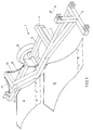
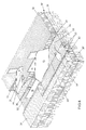
- the reversible plough 1 as shown has a frame 2 which is provided with an attachment member 3 which in known manner can be coupled to the three-point hitch of a tractor.
- the direction of travel during operation is indicated by means of an arrow P.
- the frame 2 mounts in a conventional manner a side arm 4 which pivotably carries a rearwardly directed wheel support arm 5, which is provided with a support wheel 6 which in operation rides alongside the plough furrow and serves for adjustment of the working depth.
- a bearing bushing 7 is provided which is adapted to pivot, for instance about the extended axle and which in turn carries a rearwardly extending support arm 8 on which a rear ploughshare 9 is mounted.
- the support arm 8 is suspended from a tail piece 12 of the frame 2, extending above the support arm 8, by means of attachment members which in the embodiment shown are formed by chains 10, 11.
- the frame 2 further carries a ploughshare 13 mounted at the beginning of the tail piece in the embodiment shown.
- the ploughshare 13 is located before the rear ploughshare 9 and extends much deeper than the latter.
- the rear ploughshare 9 serves to work on the top layer while the front ploughshare 13 serves to work on the subsoil.
- the two ploughshares of the reversible plough cooperate in such a way that the front or first ploughshare 13 first forms a furrow extending into the subsoil to the desired depth, after which the second ploughshare 9, located slightly further towards the rear, deposits the strip of the top layer, located adjacent to the deep furrow of the first ploughshare, in the deep furrow.
- the first ploughshare forms a next deep furrow in the subsoil at the original location of the strip of the top layer, deposited in the deep furrow.
- the material coming from the next deep furrow for instance subsoil sand, is deposited in the first deep furrow on top of the strip of the top layer already deposited therein.
- the second ploughshare ploughs a next strip of the top layer in the newly formed deep furrow. The final outcome is that the original top layer has come to lie under a layer of the original subsoil.
- the now superjacent layer of the original subsoil can be removed, for instance by means of an earth moving machine as described in applicants' Dutch patent application 8702301, to be deposited and spread elsewhere.
- the layer thus applied elsewhere can now be moved back under the original top layer at that location using a reversible plough according to the present invention.
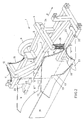
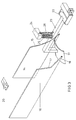
- Fig. 3 separately shows a number of such aids in their mounted position relative to each other, while Fig. 2 shows the plough with the same aids in mounted position.
- a first aid is formed by a vertical support plate 14 which travels in the deep plough furrow and brushes along the wall of the deep furrow that is located on the side of the strip of the top layer to be ploughed into the deep furrow.
- the support plate 14 is arranged directly behind the first ploughshare 13 and the front edge 15 of the support plate preferably abuts the first ploughshare as closely as possible.
- the front edge 15 of the support plate forms a curved line which corresponds to the conventional curved form of the first ploughshare 13.
- the support plate thus prevents the deep furrow from being compressed from the side as a result of the lateral cutting pressure caused by the second ploughshare. Further, the support plate 14 smoothes the corresponding wall of the deep plough furrow, thereby reinforcing the wall and preventing material from crumbling off the wall and falling into the deep furrow.
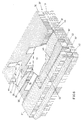
- Figs. 4-8 schematically show a soil packet comprising two layers 30, 31 whose relative position is to be reversed. Further, Figs. 4-8 schematically show the various parts of a reversible plough according to the invention which in effect cooperate with the soil. To illustrate the operation of each of the aids, only Fig. 8 shows all aids together with the ploughshares, while in each of Figs. 4-5 an aid has been omitted.
- Fig. 4 shows the effect that may occur if the support plate 14 is not used. Whether this effect actually occurs depends on the composition, degree of humidity, etc. of the soil.
- Fig. 4 shows a top layer of soil 30, for instance mould, disposed on a lower layer of soil 31, for instance sand. It is supposed that the lower layer 31 must be dug off and that for that purpose a layer of sand is to be ploughed from the lower layer 31 onto the mould, to enable subsequent removal of the instant superjacent layer of sand.
- Fig. 4 shows the second ploughshare 9 partly extending into the mould 30 and the first ploughshare 13, mounted more forwardly in laterally displaced position.
- the first ploughshare ploughs the sand packet 32 disposed before the first ploughshare, whose top layer of mould has already been removed in a previous pass and is now arranged in the location indicated by 33, onto the mould packet 30', as shown at 31'.
- the deep plough furrow 34 is to be seen, having a vertical wall 35.
- the support plate 14 is not mounted and the result thereof is a crumbling edge 36 of the deep furrow due to the pressure exerted by the second ploughshare 9.
- the crumbling soil comes to rest at the bottom of the deep furrow, as indicated at 36'.
- the layer of mould 30' eventually disposed under the layer of sand 31' no longer forms a continuous layer but is interspersed at the bottom with sand packets 36'' approximately triangular in cross-section, as shown in Fig. 4 in the plane of section 37.
- the sand packets 36'' will be mixed with the mould as a result of the normal working of the soil, which leads to deterioration of the soil.
- Figs. 2 and 3 show a second support plate 16, which also travels in the deep furrow behind the first ploughshare, but travels along the wall 38 located opposite the wall 35.
- the second support plate 16 serves to prevent the sand packet 31' just ploughed from the deep furrow from falling back into the deep furrow again after the ploughshare has passed and before the mould has been deposited at the bottom of the deep furrow.
- the second support plate comprises a forwardly extending point 18 provided at the front edge 17 at the bottom end thereof, which point extends under the laterally curving portion 19 of the first ploughshare.
- the second support plate 16 preferably extends rearwardly so far that the packet of mould deposited in the deep plough furrow by the second ploughshare falls against the second support plate.
- Fig. 5 shows the effect that may occur, but not necessarily so, if the second support plate 16 is not used. In that case sand 31' ploughed from the deep furrow 34 may fall back into the deep furrow before the mould 30' has been deposited in the deep furrow.
- Fig. 5 illustrates the result in the form of sand packets 39 approximately triangular in cross-section.
- the support plate 16 brushes along the corresponding wall of the deep furrow, thereby reinforcing that wall. Together the support plates 14 and 16 keep the deep furrow clear until the second ploughshare deposits the mould in the deep furrow.
- Figs. 2 and 3 show a third aid in the form of lateral knife coulter 20, which is arranged substantially horizontally behind and next to the second ploughshare 9 and which makes a horizontal cut in the as yet unworked soil at the height of the boundary surface between the mould and the subsoil.
- Figs. 4, 5, 6 and 8 show the horizontal cut at 21.
- the horizontal cut 21 contributes to the second ploughshare, extending as deep as the lateral knife coulter 20, exclusively depositing mould 30 in the deep furrow 34. If the horizontal knife coulter is not used, as is shown in Fig. 7, the chance exists that along with the mould also subsoil sand will fall into the deep furrow.
- Fig. 7 shows the crumbled lower edge of the deep furrow and the soil fallen into the deep furrow at 40 and 40', respectively.
- sand packets 40' partly disposed between the mould packets 30', are formed in a similar manner as in the case where the support plate 14 is omitted.
- Figs. 2 and 3 finally, show a fourth aid in the form of a float 51 which serves to press on and smooth the mould ploughed into the deep furrow.
- the float 51 is mounted on the rear end of an arm 23 extending rearwardly from the front portion of the plough frame and mounted for pivoting movement about a horizontal shaft 22.
- a compression spring 25 Arranged between the arm 23 and a fixed bar 24 provided above the arm and mounted on the frame 2 is a compression spring 25 which resiliently presses the float down.
- height adjustment means mounted further between the fixed bar 24 and the arm 23 are formed by a chain 26 which limits the travel of the arm 23.
- the float 51 comprises a rectangular plate inclined slightly upwardly in the direction of travel of the plough. As shown, the plate is preferably curved in a direction transverse to the direction of travel and the concave side of the plate is turned towards the ground. In the embodiment shown the float is disposed before the first ploughshare, displaced outwardly in a direction which is opposite to that in which the second ploughshare has been displaced outwardly relative to the first ploughshare.
- the float has substantially the same working width as the two ploughshares.
- the float levels the mould already ploughed, in a previous pass, in the deep furrow formed then.
- the float brings a pressure to bear on the mould and retains it at the moment when the first ploughshare exerts a lateral pressure on the mould via the subsoil sand in the location indicated by 33. In this manner the mould is prevented from being pushed away laterally by the subsoil sand.
- Fig. 6 further illustrates this.
- the float 51 is not used.
- Fig. 6 indicates at 42 how in that case the mould ploughed into the deep furrow in the preceding pass can be pushed away laterally by the soil moved up by the second ploughshare 13. The result is that a wedge-shaped strip of Sand 42' is formed at the top between adjacent strips of mould, as can be seen in Fig. 6 in the sectional plane 37.
- Fig. 8 schematically shows the operation of a reversible plough according to the invention which is provided with all aids discussed. It can be seen that the strips of mould 30' ploughed into the adjacent deep furrow in successive passes accurately adjoin one another and also have a flat top surface. This last is necessary to enable later, accurate and exclusive removal of the layer 31'.
- a vertical knife coulter can be used that precedes the first ploughshare.
- a coulter for instance a disk coulter, may be provided before the second ploughshare.
- means may be provided which, prior to the passage of the first ploughshare, smooth the side wall 44 (Fig. 8) of the firm mould, and thereby reinforce it.
- Such means may comprise a vertical float arranged behind the second ploughshare.
- a plough according to the invention may naturally be of multiple construction so that in a single pass a plurality of deep furrows are formed and then filled with soil from the original top layer.
Landscapes
- Life Sciences & Earth Sciences (AREA)
- Engineering & Computer Science (AREA)
- Mechanical Engineering (AREA)
- Soil Sciences (AREA)
- Environmental Sciences (AREA)
- Soil Working Implements (AREA)
Claims (14)
- Methode zur Umkehr der Reihenfolge einer oberen Bodenschicht (30) und einer unteren Bodenschicht (31), wobei in einem ersten Arbeitsgang eine sich bis in die untere Bodenschicht (31) erstreckende erste tiefe Furche (34) mittels einer ersten Pflugschar (13) gezogen wird und der aus dieser tiefen Furche gepflügte Boden auf einer Seite der tiefen Furche (34) abgelagert wird, wobei gleichzeitig der auf der anderen Seite neben der tiefen Furche liegende Streifen der oberen Bodenschicht durch eine zweite Pflugschar (9) in die tiefe Furche gepflügt wird, und wobei in einem zweiten Arbeitsgang an der Ursprungsstelle des in die erste tiefe Furche (34) gepflügten Streifens der oberen Bodenschicht eine nächste tiefe Furche (34) gebildet wird und der aus der nächsten tiefen Furche (34) kommende Boden auf dem in die erste tiefe Furche (34) gepflügten Boden der oberen Schicht abgelagert wird, dadurch gekennzeichnet, daß beide Seitenwände (35, 38) der tiefen Furche (34) geglättet und seitlich unterstützt werden, bevor und während der Boden der oberen Schicht in die tiefe Furche (34) gepflügt wird.
- Methode nach Anspruch 1, dadurch gekennzeichnet, daß der in eine tiefe Furche (34) gepflügte Boden der oberen Schicht auf der Oberseite geglättet und angedrückt wird, bevor der aus einer nächsten tiefen Furche (34) kommende Boden auf den in die tiefe Furche (34) gepflügten Boden der oberen Schicht gepflügt wird.
- Methode nach einem der vorhergehenden Ansprüche, dadurch gekennzeichnet, daß ein horizontaler Einschnitt (21) auf der Höhe der Unterseite der oberen Bodenschicht (30) gemacht wird, bevor die obere Bodenschicht (30) in eine benachbarte tiefe Furche (34) gepflügt wird.
- Methode nach einem der vorhergehenden Ansprüche, dadurch gekennzeichnet, daß der in eine erste tiefe Furche (34) gepflügte Boden der oberen Schicht (30) gegen seitlichen Druck, ausgehend von der ersten Pflugschar (13), festgehalten wird, während der Boden aus einer neben der ersten tiefen Furche (34) gebildeten zweiten tiefen Furche (34) auf den in die erste tiefe Furche (34) gepflügten Boden gepflügt wird.
- Pflug zur Umkehr der Reihenfolge einer oberen Bodenschicht (30) und einer unteren Bodenschicht (31), versehen mit wenigstens einer ersten Pflugschar (13), die auf eine der Dicke der oberen Bodenschicht (30) und der unteren Bodenschicht (31) entsprechende Tiefe eingestellt ist, um eine tiefe Furche (34) zu bilden, und mit wenigstens einer zweiten Pflugschar (9), die auf eine der Dicke der oberen Bodenschicht (30) entsprechende Tiefe eingestellt ist, wobei die erste Pflugschar (13) dieselbe Arbeitsbreite wie die zweite Pflugschar (9) hat und seitlich über einen Abstand gleich der Arbeitsbreite sowie in Vorwärtsrichtung relativ zu der zweiten Pflugschar (9) verschoben worden ist, so daß die zweite Pflugschar (9) einen Streifen der oberen Bodenschicht (30) in einer tiefen Furche (34) neben dem durch die erste Pflugschar (13) gebildeten Streifen ablagern kann, dadurch gekennzeichnet, daß weiter hinter der ersten Pflugschar (13) Stützmittel (14, 16) vorgesehen sind, die über beide Seitenwände der tiefen Furche (34) streichen und diese glätten, um die tiefe Furche offenzuhalten.
- Pflug nach Anspruch 5, dadurch gekennzeichnet, daß die Stützmittel eine hinter der ersten Pflugschar (13) angeordnete erste vertikale Stützplatte (14), die im Betrieb die nahe der zweiten Pflugschar (9) liegende Wand (35) der tiefen Furche (34) stützt und über diese streicht, und eine hinter der ersten Pflugschar (13) angeordnete zweite vertikale Stützplatte (16), die im Betrieb die von der zweiten Pflugschar (9) abgekehrte Wand (38) der tiefen Furche (34) stützt und über diese streicht, umfassen.
- Pflug nach Anspruch 6, dadurch gekennzeichnet, daß die zweite Stützplatte (14) sich rückwärts bis in den Arbeitsbereich der zweiten Pflugschar (9) erstreckt.
- Pflug nach Anspruch 6, dadurch gekennzeichnet, daß die erste und/oder zweite vertikale Stützplatte (14, 16) eine in Anpassung an die Form der ersten Pflugschar (13) gebogene Vorderkante (15, 17, 18) aufweist.
- Pflug nach einem der Ansprüche 5 bis 8, gekennzeichnet durch mindestens ein horizontales Messersech (20), das im Betrieb einen horizontalen Einschnitt (21) auf der Höhe der Unterseite der oberen Bodenschicht (30) macht, bevor die obere Bodenschicht (30) von der zweiten Pflugschar (9) bewegt wird.
- Pflug nach Anspruch 9, dadurch gekennzeichnet, daß das mindestens eine horizontale Messersech (20) hinter der zweiten Pflugschar (9) angeordnet ist.
- Pflug nach einem der Ansprüche 5 bis 10, gekennzeichnet durch mindestens eine Streichplatte (51), die den in einer tiefen Furche (34) abgelagerten Boden der oberen Schicht (30') glättet und andrückt.
- Pflug nach Anspruch 11, dadurch gekennzeichnet, daß mindestens eine Streichplatte (51) seitlich versetzt vor der ersten Pflugschar (13) angeordnet ist.
- Pflug nach Anspruch 11 oder 12, dadurch gekennzeichnet, daß die Streichplatte (51) im Betrieb unter Federspannung gegen den Boden (30') gedrückt wird.
- Pflug nach Anspruch 11 bis 13, dadurch gekennzeichnet, daß die Streichplatte (51) eine im wesentlichen rechteckige Platte ist, die quer zur Fortbewegungsrichtung gebogen ist und in der Fortbewegungsrichtung gesehen ein wenig aufwärts geneigt angeordnet ist.
Priority Applications (2)
| Application Number | Priority Date | Filing Date | Title |
|---|---|---|---|
| EP19900202564 EP0477437B1 (de) | 1990-09-28 | 1990-09-28 | Methode zur Umkehr der Reihenfolge zweier übereinanderliegenden Bodenschichten und ein umdrehbarer Pflug zur Anwendung besagter Methode |
| DE1990605305 DE69005305T2 (de) | 1990-09-28 | 1990-09-28 | Methode zur Umkehr der Reihenfolge zweier übereinanderliegenden Bodenschichten und ein umdrehbarer Pflug zur Anwendung besagter Methode. |
Applications Claiming Priority (1)
| Application Number | Priority Date | Filing Date | Title |
|---|---|---|---|
| EP19900202564 EP0477437B1 (de) | 1990-09-28 | 1990-09-28 | Methode zur Umkehr der Reihenfolge zweier übereinanderliegenden Bodenschichten und ein umdrehbarer Pflug zur Anwendung besagter Methode |
Publications (2)
| Publication Number | Publication Date |
|---|---|
| EP0477437A1 EP0477437A1 (de) | 1992-04-01 |
| EP0477437B1 true EP0477437B1 (de) | 1993-12-15 |
Family
ID=8205129
Family Applications (1)
| Application Number | Title | Priority Date | Filing Date |
|---|---|---|---|
| EP19900202564 Expired - Lifetime EP0477437B1 (de) | 1990-09-28 | 1990-09-28 | Methode zur Umkehr der Reihenfolge zweier übereinanderliegenden Bodenschichten und ein umdrehbarer Pflug zur Anwendung besagter Methode |
Country Status (2)
| Country | Link |
|---|---|
| EP (1) | EP0477437B1 (de) |
| DE (1) | DE69005305T2 (de) |
Cited By (1)
| Publication number | Priority date | Publication date | Assignee | Title |
|---|---|---|---|---|
| EP4381921A1 (de) * | 2022-12-08 | 2024-06-12 | Rafko Znidaric s.p. | Pflug für tiefe bodenbearbeitung |
Families Citing this family (2)
| Publication number | Priority date | Publication date | Assignee | Title |
|---|---|---|---|---|
| DE102018120092A1 (de) * | 2018-08-17 | 2020-02-20 | Rheinische Friedrich-Wilhelms-Universität Bonn | Verfahren zur Bodenbearbeitung und/oder zur Bodenmodifikation durch Einbringen von wachstumsförderndem organischem Material in einen Ackerboden |
| RU2768733C1 (ru) * | 2021-04-27 | 2022-03-24 | Федеральное государственное бюджетное образовательное Учреждение высшего образования "Воронежский государственный аграрный университет имени императора Петра I" (ФГБОУ ВО Воронежский ГАУ) | Способ отвальной вспашки и устройство для его осуществления |
Family Cites Families (1)
| Publication number | Priority date | Publication date | Assignee | Title |
|---|---|---|---|---|
| NL92304C (de) * | 1900-01-01 |
-
1990
- 1990-09-28 DE DE1990605305 patent/DE69005305T2/de not_active Expired - Fee Related
- 1990-09-28 EP EP19900202564 patent/EP0477437B1/de not_active Expired - Lifetime
Cited By (1)
| Publication number | Priority date | Publication date | Assignee | Title |
|---|---|---|---|---|
| EP4381921A1 (de) * | 2022-12-08 | 2024-06-12 | Rafko Znidaric s.p. | Pflug für tiefe bodenbearbeitung |
Also Published As
| Publication number | Publication date |
|---|---|
| DE69005305D1 (de) | 1994-01-27 |
| DE69005305T2 (de) | 1994-05-19 |
| EP0477437A1 (de) | 1992-04-01 |
Similar Documents
| Publication | Publication Date | Title |
|---|---|---|
| US6276462B1 (en) | Combination tillage equipment for providing a smooth finish | |
| US6425445B1 (en) | Enhanced minimum tillage planter/renovator system | |
| US7975631B2 (en) | Combined agricultural machine | |
| US4633791A (en) | Opener assembly including a compact, arc-shaped opener | |
| AU716090B2 (en) | Tine for mounting on soil-working implement | |
| EP0477437B1 (de) | Methode zur Umkehr der Reihenfolge zweier übereinanderliegenden Bodenschichten und ein umdrehbarer Pflug zur Anwendung besagter Methode | |
| US5984017A (en) | Multi-function tillage apparatus and method | |
| US4328870A (en) | Plough for working of soil | |
| RU2140136C1 (ru) | Способ подготовки верхнего посевного влагосберегающего слоя почвы и прицепное к плугам или плоскорезам комбинированное почвообрабатывающее приспособление для его осуществления | |
| US6009955A (en) | Enhanced minimum tillage planter/renovator system | |
| CA1159703A (en) | Ridge mulch tillage method and apparatus | |
| US20020056407A1 (en) | Disc opener | |
| EP2346312B1 (de) | Bodenbewirtschaftung | |
| CA1203717A (en) | Tillage implement | |
| RU2644197C1 (ru) | Грядоделатель | |
| RU2040134C1 (ru) | Плуг-плоскорез | |
| JP2676140B2 (ja) | 乗用型不耕起移植機 | |
| RU2124825C1 (ru) | Комбинированное орудие | |
| SU1727554A1 (ru) | Многокорпусный плуг Е.М.Тлеужанова | |
| RU2655954C1 (ru) | Грядоделатель | |
| JP2534331Y2 (ja) | 不耕起播種における覆土装置 | |
| SU871749A2 (ru) | Почвообрабатывающее орудие | |
| AU733413B3 (en) | A disc opener | |
| SU1547718A1 (ru) | Плуг | |
| JP2514498Y2 (ja) | 不耕起ロ―タリにおける溝掘装置 |
Legal Events
| Date | Code | Title | Description |
|---|---|---|---|
| PUAI | Public reference made under article 153(3) epc to a published international application that has entered the european phase |
Free format text: ORIGINAL CODE: 0009012 |
|
| AK | Designated contracting states |
Kind code of ref document: A1 Designated state(s): AT BE CH DE DK ES FR GB GR IT LI LU NL SE |
|
| 17P | Request for examination filed |
Effective date: 19920403 |
|
| RBV | Designated contracting states (corrected) |
Designated state(s): DE FR GB IT NL |
|
| 17Q | First examination report despatched |
Effective date: 19920604 |
|
| GRAA | (expected) grant |
Free format text: ORIGINAL CODE: 0009210 |
|
| AK | Designated contracting states |
Kind code of ref document: B1 Designated state(s): DE FR GB IT NL |
|
| REF | Corresponds to: |
Ref document number: 69005305 Country of ref document: DE Date of ref document: 19940127 |
|
| ET | Fr: translation filed | ||
| ITF | It: translation for a ep patent filed | ||
| PLBE | No opposition filed within time limit |
Free format text: ORIGINAL CODE: 0009261 |
|
| STAA | Information on the status of an ep patent application or granted ep patent |
Free format text: STATUS: NO OPPOSITION FILED WITHIN TIME LIMIT |
|
| 26N | No opposition filed | ||
| PGFP | Annual fee paid to national office [announced via postgrant information from national office to epo] |
Ref country code: NL Payment date: 19971031 Year of fee payment: 8 |
|
| PGFP | Annual fee paid to national office [announced via postgrant information from national office to epo] |
Ref country code: FR Payment date: 19980917 Year of fee payment: 9 |
|
| PGFP | Annual fee paid to national office [announced via postgrant information from national office to epo] |
Ref country code: DE Payment date: 19980924 Year of fee payment: 9 |
|
| PGFP | Annual fee paid to national office [announced via postgrant information from national office to epo] |
Ref country code: GB Payment date: 19981001 Year of fee payment: 9 |
|
| PG25 | Lapsed in a contracting state [announced via postgrant information from national office to epo] |
Ref country code: NL Free format text: LAPSE BECAUSE OF NON-PAYMENT OF DUE FEES Effective date: 19990401 |
|
| NLV4 | Nl: lapsed or anulled due to non-payment of the annual fee |
Effective date: 19990401 |
|
| PG25 | Lapsed in a contracting state [announced via postgrant information from national office to epo] |
Ref country code: GB Free format text: LAPSE BECAUSE OF NON-PAYMENT OF DUE FEES Effective date: 19990928 |
|
| GBPC | Gb: european patent ceased through non-payment of renewal fee |
Effective date: 19990928 |
|
| PG25 | Lapsed in a contracting state [announced via postgrant information from national office to epo] |
Ref country code: FR Free format text: LAPSE BECAUSE OF NON-PAYMENT OF DUE FEES Effective date: 20000531 |
|
| PG25 | Lapsed in a contracting state [announced via postgrant information from national office to epo] |
Ref country code: DE Free format text: LAPSE BECAUSE OF NON-PAYMENT OF DUE FEES Effective date: 20000701 |
|
| REG | Reference to a national code |
Ref country code: FR Ref legal event code: ST |
|
| PG25 | Lapsed in a contracting state [announced via postgrant information from national office to epo] |
Ref country code: IT Free format text: LAPSE BECAUSE OF NON-PAYMENT OF DUE FEES Effective date: 20050928 |