EP0476909B1 - Endverschluss eines mineralisolierten elektrischen Kabels - Google Patents
Endverschluss eines mineralisolierten elektrischen Kabels Download PDFInfo
- Publication number
- EP0476909B1 EP0476909B1 EP91308263A EP91308263A EP0476909B1 EP 0476909 B1 EP0476909 B1 EP 0476909B1 EP 91308263 A EP91308263 A EP 91308263A EP 91308263 A EP91308263 A EP 91308263A EP 0476909 B1 EP0476909 B1 EP 0476909B1
- Authority
- EP
- European Patent Office
- Prior art keywords
- tube
- end wall
- wall
- mineral insulated
- extending
- Prior art date
- Legal status (The legal status is an assumption and is not a legal conclusion. Google has not performed a legal analysis and makes no representation as to the accuracy of the status listed.)
- Expired - Lifetime
Links
- 229910052500 inorganic mineral Inorganic materials 0.000 title claims abstract description 68
- 239000011707 mineral Substances 0.000 title claims abstract description 68
- 239000004020 conductor Substances 0.000 claims abstract description 41
- 230000000694 effects Effects 0.000 claims abstract description 17
- 150000001875 compounds Chemical class 0.000 claims abstract description 15
- 229910052751 metal Inorganic materials 0.000 claims description 8
- 239000002184 metal Substances 0.000 claims description 8
- 230000000295 complement effect Effects 0.000 claims description 5
- 239000012777 electrically insulating material Substances 0.000 claims description 4
- 229910001092 metal group alloy Inorganic materials 0.000 claims description 2
- 229920002457 flexible plastic Polymers 0.000 abstract 1
- 239000000919 ceramic Substances 0.000 description 4
- 238000007789 sealing Methods 0.000 description 4
- 239000011810 insulating material Substances 0.000 description 3
- 239000000463 material Substances 0.000 description 3
- HUWSZNZAROKDRZ-RRLWZMAJSA-N (3r,4r)-3-azaniumyl-5-[[(2s,3r)-1-[(2s)-2,3-dicarboxypyrrolidin-1-yl]-3-methyl-1-oxopentan-2-yl]amino]-5-oxo-4-sulfanylpentane-1-sulfonate Chemical compound OS(=O)(=O)CC[C@@H](N)[C@@H](S)C(=O)N[C@@H]([C@H](C)CC)C(=O)N1CCC(C(O)=O)[C@H]1C(O)=O HUWSZNZAROKDRZ-RRLWZMAJSA-N 0.000 description 2
- 229940125810 compound 20 Drugs 0.000 description 2
- JAXFJECJQZDFJS-XHEPKHHKSA-N gtpl8555 Chemical compound OC(=O)C[C@H](N)C(=O)N[C@@H](CCC(O)=O)C(=O)N[C@@H](C(C)C)C(=O)N[C@@H](C(C)C)C(=O)N1CCC[C@@H]1C(=O)N[C@H](B1O[C@@]2(C)[C@H]3C[C@H](C3(C)C)C[C@H]2O1)CCC1=CC=C(F)C=C1 JAXFJECJQZDFJS-XHEPKHHKSA-N 0.000 description 2
- 238000009434 installation Methods 0.000 description 2
- 239000004033 plastic Substances 0.000 description 2
- 229920003023 plastic Polymers 0.000 description 2
- 239000000843 powder Substances 0.000 description 2
- 239000004568 cement Substances 0.000 description 1
- 239000000395 magnesium oxide Substances 0.000 description 1
- CPLXHLVBOLITMK-UHFFFAOYSA-N magnesium oxide Inorganic materials [Mg]=O CPLXHLVBOLITMK-UHFFFAOYSA-N 0.000 description 1
- AXZKOIWUVFPNLO-UHFFFAOYSA-N magnesium;oxygen(2-) Chemical compound [O-2].[Mg+2] AXZKOIWUVFPNLO-UHFFFAOYSA-N 0.000 description 1
- 230000035515 penetration Effects 0.000 description 1
- XLYOFNOQVPJJNP-UHFFFAOYSA-N water Substances O XLYOFNOQVPJJNP-UHFFFAOYSA-N 0.000 description 1
Images




Classifications
-
- H—ELECTRICITY
- H02—GENERATION; CONVERSION OR DISTRIBUTION OF ELECTRIC POWER
- H02G—INSTALLATION OF ELECTRIC CABLES OR LINES, OR OF COMBINED OPTICAL AND ELECTRIC CABLES OR LINES
- H02G15/00—Cable fittings
- H02G15/02—Cable terminations
- H02G15/04—Cable-end sealings
- H02G15/043—Cable-end sealings with end caps, e.g. sleeve closed at one end
- H02G15/046—Cable-end sealings with end caps, e.g. sleeve closed at one end with bores or protruding portions allowing passage of cable conductors
Definitions
- This invention relates to the termination of mineral insulated electric cables, that is to say cables of the kind comprising at least one conductor insulated from a surrounding metal sheath, and where there is more than one conductor from the other conductor or conductors, by compacted mineral insulating powder, usually but not necessarily magnesium oxide.
- Compacted mineral insulating powder is particularly vulnerable to water penetration and it is the general practice to protect an end of a mineral insulated cable against the ingress of moisture by a metal sealing pot which is screwed or otherwise secured to the cable sheath and which is filled with waterproof sealing compound.
- Assembly of a sealing pot on an end of a mineral insulated electric cable in such a way as to provide an effective waterproof termination requires a degree of skill and the time taken to terminate mineral insulated electric cables of a mineral insulated electric cable installation contributes to a substantial proportion of the overall cost of the installation.
- GB-A-2 227 617 discloses a mineral insulated cable termination in which a preformed insulating cap, which comprises a tube open at one end and closed at the other by an integral end wall, is applied over the cut back end of the cable.
- an improved mineral insulated electric cable termination comprises a tube of flexible electrically insulating material which at one end of the tube fits over the cut-back sheath of the cable and which at the other end of the tube is closed by an end wall spaced from the end face of the cable, the or each cable conductor passing through a throughbore or one of a plurality of throughbores in the end wall and, filling the space within the tube between the end face of the cable and said end wall, waterproof electrically insulating compound, wherein at a first position around the circumferential wall of the tube the wall is slit throughout its length and radial thickness and at at least one position circumferentially spaced from said first position the wall is adapted to constitute a hinge extending throughout the length of the wall, the abutting longitudinally extending parts of the wall at said first position being so shaped that one effects a snap fit with the other throughout the length of the tube.
- the tube When assembling the improved mineral insulated electric cable termination on an end of the cable, the tube is presented to the cut-back end of the cable in its open state; before or after the or each cable conductor is or has been threaded through the throughbore or throughbores in the end wall of the tube, at least one of the hinged parts of the tube is substantially filled with waterproof electrically insulating compound; and the parts of the tube are then applied to the cut-back end of the cable and snapped together so that the space within the tube between the cut-back end of the cable and the end wall of the tube is substantially filled with waterproof electrically insulating compound, any excess compound being squeezed out of the tube between the or each conductor and the surrounding boundary wall of the throughbore through which it passes.
- the abutting longitudinally extending parts of the circumferential wall at said first position may be of any complementary shapes that will effect a snap fit with one another throughout the length of the tube but, preferably, one of said two abutting parts has extending longitudinally throughout its length an outwardly extending protuberance which effects a snap fit in a groove of complementary cross-sectional shape extending longitudinally throughout the length of the inner surface of the other part.
- the circumferential wall of the tube at the or each position circumferentially spaced from said first position is of such a transverse cross-sectional shape and/or of such a radial thickness that the wall at this position effectively constitutes a hinge.
- the circumferential wall of the tube is adapted to constitute a hinge extending throughout the length of the wall at a second position substantially diametrically opposite said first position and, in this case, the end wall of the tube may be integral with one of the two hinged parts of the tube or it may be slit substantially diametrically from said first position to said second position so that each part of the end wall is integral with one of the two hinged parts of the tube.
- the end wall of the tube is slit transversely over a part of its width extending from said first position along its diameter and over the majority of the remainder of its width along two substantially parallel planes on opposite sides of the axis of the end wall dividing the end wall into a central portion and two other portions, the diametrically extending slit containing the axis of one throughbore and each of said two parallel slits containing the axis of one of the other two throughbores, and the circumferential wall of the tube at two circumferentially spaced positions extending from the closed ends of the two parallel slits in the end wall and throughout the length of the circumferential wall is adapted to constitute two circumferentially spaced hinges.
- the end wall of the tube is slit transversely over the majority of its width along two substantially parallel planes on opposite sides of the axis of the end wall dividing the end wall into a central portion and two other portions, one of said two parallel slits containing the axis of a first throughbore or the axes of two throughbores in said end wall and the other of said two parallel slits containing the axis of the second throughbore or the axes of third and fourth throughbores in said end wall, and the circumferential wall of the tube at two circumferentially spaced positions extending from the closed ends of the slits in the end wall and throughout the length of the circumferential wall is adapted to constitute two circumferentially spaced hinges.
- the end wall may consist of a separately formed button of ceramic or vitreous insulating material secured within the tube at or near said other end.
- the tube is closed at said other end by an end wall integral with at least one of the hinged parts of the tube and by a button of ceramic or vitreous insulating material secured within the tube at or near said closed end, the or each conductor of the cable passing through axially aligned throughbores in the button and said end wall.
- An embodiment in which said other end of the tube is closed by an end wall integral with at least one of the hinged parts of the tube and/or by a separately formed button has the important advantage that, after the or each cable conductor has been passed through the throughbore or throughbores in the end wall and/or button and insulating compound has been disposed in one or each part of the tube, as the hinged parts of the tube are closed the mineral insulated cable can be urged axially towards said other end of the tube thereby acting as a piston compressing the insulating compound within the space bounded by the tube and out of the tube between the or each conductor and the surrounding boundary wall of the throughbore through which it passes.
- the end wall of the tube both when it is integral with at least one of the hinged parts of the tube and when it is a separately formed button of ceramic or vitreous insulating material, preferably has extending lengthwise and outwardly from the end wall a sleeve or two or more sleeves in substantially axial alignment with the throughbore or throughbores in the end wall and surrounding the cable conductor or conductors.
- the axis of the or each throughbore may lie on said diametrically extending slit and the or each sleeve may be slit transversely throughout its length so that one part of the sleeve is integral with one portion of the end wall and the other part of the sleeve is integral with the other portion of the end wall.
- each of the sleeves may be slit transversely throughout its length so that one part of the sleeve is integral with the central portion of the end wall and the other part of the sleeve is integral with one of the other portions of the end wall.
- the button has means positively preventing movement of the button with respect to the tube in a direction away from the said other end of the tube.
- the internal surface of the wall of the tube near said other end may have a peripherally continuous groove in which the button fits and within which it may be permanently secured by an appropriate cement.
- the internal diameter of the throughbore increases smoothly in a direction towards the end face of the cable to form, in effect, a throat into which a conductor can be readily guided.
- the circumferential wall of that part of the length of the tube which fits over the cut-back sheath of the cable has in and protruding inwardly from the circumferential wall a device of metal or metal alloy whose protruding part so mechanically engages with and secures the tube to the cable sheath as to restrain the tube against removal from the cable.
- the metal retaining device is a clip which has a protruding part of substantially C-shape between the limbs of which the cable sheath is a force fit.
- the radially inner edge of the C-shaped clip may have one or more than one inwardly extending tooth of such a shape that it bites into the cable sheath and serves to restrain the tube against rotational movement on and with respect to the cable.
- the invention also includes, for use in the assembly of an improved mineral insulated electric cable termination as hereinbefore described, an improved mineral insulated cable terminating device comprising a tube of flexible electrically insulating material open at one end and closed at or near its other end by an end wall having therein at least one throughbore, wherein at a first position around the circumferential wall of the tube the wall is slit throughout its length and radial thickness and at at least one position circumferentially spaced from said first position the wall is adapted to constitute a hinge extending throughout the length of the wall, the longitudinally extending parts of the wall at said first position being so shaped that one is adapted to effect a snap fit with the other throughout the length of the tube.
- a mineral insulated electric cable with which the improved mineral insulated cable terminating device is to be used has one conductor or two conductors
- the circumferential wall of the tube is adapted to constitute a hinge extending throughout the length of the wall at a second position substantially diametrically opposite said first position and the end wall is slit substantially diametrically from said first position to said second position so that each part of the end wall is integral with one of the two parts of the tube.
- a mineral insulated electric cable with which the improved mineral insulated cable terminating device is to be used has three conductors, preferably the end wall of the tube is slit transversely over a part of its width extending from said first position along its diameter and over the majority of the remainder of its width along two substantially parallel planes on opposite sides of the axis of the end wall dividing the end wall into a central portion and two other portions, the diametrically extending slit containing the axis of one throughbore and each of said two parallel slits containing the axis of one of the other two throughbores.
- a mineral insulated electric cable with which the improved mineral insulated cable terminating device is to be used has two or four conductors, preferably the end wall of the tube is slit transversely over the majority of its width along two parallel planes on opposite sides of the axis of the end wall, one of said two parallel slits containing the axis of a first throughbore or the axes of two throughbores in said end wall and the other of said two parallel slits containing the axis of the second or the axes of third and fourth throughbores in said end wall.
- the circumferential wall of the tube at two circumferentially spaced positions extending from the closed ends of the slits in the end wall and throughout the length of the circumferential wall is adapted to constitute two circumferentially spaced hinges.
- At least one of the hinged parts of the tube may be pre-filled with waterproof electrically insulating compound of a grease-like nature.
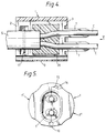
- the mineral insulated cable terminating device to be used in the first preferred mineral insulated electric cable termination comprises a tube 1 of electrically insulating plastics material which at one end has an end wall 2 having a centrally disposed throughbore 4 of a diameter such that the tube will effect a tight fit over the cut-back sheath of a mineral insulated electric cable and which at the other end has an end wall 3 having two throughbores 6 for passage of conductors of the cable and, extending outwardly from the end wall 3, two sleeves 7 in axial alignment with the throughbores.
- the wall is slit throughout its length and radial thickness so that the tube consists of two hinged parts 1′, 1 ⁇ , and, at a second position substantially diametrically opposite the first position, the circumferential wall is of such a transverse cross-sectional shape and radial thickness that the wall at the second position effectively constitutes a hinge 10.
- the end wall 3 is slit diametrically from said first position 9 to the hinge 10 so that each of the two portions of the end wall is integral with one of the two hinged parts 1′, 1 ⁇ of the tube 1.
- each throughbore 6 in the end wall 3 lies on the diametrically extending slit in the end wall and each sleeve 7 is slit transversely throughout its length so that one part of the sleeve is integral with one portion of the end wall and the other part of the sleeve is integral with the other portion of the end wall.
- One of the two abutting parts of the circumferential wall 8 of the tube 1 at the first position 9 has extending throughout its length an outwardly extending protruberence 14 which will effect a snap-fit in a groove 15 of complementary cross-sectional shape extending longitudinally throughout the length of the inner surface of the other part.
- the portion of the end wall 2 integral with each hinged part 1′, 1 ⁇ of the tube 1 has between its inner and outer end faces a recess 16 of substantially semi-circular shape and the circumferential wall of the hinged part 1′ of the tube has in and protruding inwardly from the circumferential wall into the recess 16 a metal clip 17 of substantially C-shape, the limbs of the C-shaped clip being so spaced apart that, when the tube is fitted over the cut-back sheath of a cable, they will mechanically engage with and secure the tube to the cut-back sheath to restrain the tube against removal from the cable.
- each hinged part 1′, 1 ⁇ of the tube 1 the portions of the end walls 2, 3 and the circumferential wall 8 bound a well 18 and, in the hinged part 1′ of the tube the well 18 is bounded on three sides by an upstanding wall 19 which, when the two hinged parts of the tube are closed together, will bear against the internal surface of the well of the hinged part 1 ⁇ .
- the well 18 of one of the hinged parts 1′, 1 ⁇ of the tube 1 may be pre-filled with waterproof electrically insulating compound of a grease-like nature (not shown).
- the hinged parts 1′, 1 ⁇ of the tube 1 are then closed so that the protruberence 14 effects a snap-fit in the groove 15 and the end wall 2 effects a tight fit on the cut-back sheath S of the cable, the limbs of the C-shaped clip 17 mechanically engaging with and securing the tube to the sheath so as to restrain the tube against removal from the cable.
- Excess insulating compound 20 is squeezed out of the tube 1 between each conductor C and the surrounding boundary wall of the throughbore 6 through which the conductor passes.
- the mineral insulated cable terminating device to be used in the second preferred mineral insulated cable termination comprises a tube 21 of electrically insulating plastics material which at one end has an end wall 22 having a centrally disposed throughbore 24 of a diameter such that the tube will effect a tight fit over the cut-back sheath of a mineral insulated electric cable and which at the other end has an end wall 23 having three throughbores 26 for passage of conductors of the cable and, extending outwardly from the end wall 3, three sleeves 27 in axial alignment with the throughbores.
- the wall is slit throughout its length and radial thickness so that the tube consists of two hinged parts 21′, 21 ⁇ , and, at two circumferentially spaced positions around the circumferential wall, the circumferential wall is of such a transverse cross-sectional shape and radial thickness that the wall at these positions effectively constitutes hinges 30.
- the end wall 23 is slit transversely over a part 32 of its width extending from the first position 29 along its diameter and over the majority of the remainder of its width along two substantially parallel planes 33 on opposites sides of the axis of the end wall dividing the end wall into a central portion 23′ and two other portions 23 ⁇ .
- the diametrically extending slit 32 contains the axis of one throughbore 26 and each of said two parallel slits 33 contains the axis of one of the other two throughbores.
- the end wall 22 is slit transversely over a part of its width extending from said first position along its diameter to the throughbore 24 and over the majority of the remainder of its width from said throughbore along said two parallel planes.
- Each sleeve 27 is slit transversely throughout its length so that one part of each of two of the sleeves is integral with the central portion 23′ of the end wall 23 and the other part of said sleeve is integral with one of the other portions 23 ⁇ of the end wall and so that each part of the third sleeve is integral with one of said other portions 23 ⁇ of the end wall.
- One of the two abutting parts of the circumferential wall 28 of the tube 21 at the first position 29 has extending throughout its length an outwardly extending protruberence 34 which will effect a snap fit in a groove 35 of complementary cross-sectional shape extending longitudinally throughout the length of the inner surface of the other part.
- the portion 22 ⁇ of the end wall 22 integral with each hinged part 21′, 21 ⁇ of the tube 21 has between its inner and outer end faces a recess 36 of substantially arcuate shape and that part of the circumferential wall 28 integral with the central portion 22′ of the end wall 22 has therein and protruding inwardly therefrom a metal clip 37 of substantially C-shape, the limbs of the C-shaped clip being so spaced apart that, when the tube is fitted over the cut-back sheath of a cable, they will mechanically engage with and secure the tube to the cut-back sheath to restrain the tube against removal of the cable.
- each hinged part 21′,21 ⁇ of the tube 21 the portions of the end walls 22, 23 and the circumferential wall 28 bound a well 38 and the well of one of the hinged parts of the tube may be pre-filled with waterproof electrically insulating compound of a grease-like nature (not shown).
- the end wall Along a transversely extending line interconnecting the diametrically extending slit in the end wall 23 and the parallel slits therein the end wall has a step 25 intermediate of its inner and outer end surfaces so that parts of the portions 23 ⁇ of the end wall will overlie a part of the central portion 23′ of the end wall when the hinged parts 21′,21 ⁇ are closed together.
- the hinged parts 21′, 21 ⁇ of the tube 21 are then closed so that the protruberence 34 effects a snap fit in the groove 35 and the end wall 22 effects a tight fit on the cut-back sheath S of the cable, the limbs of the C-shaped clip 37 mechanically engaging with and securing the tube to the sheath so as to restrain the tube against removal from the cable.
- Excess insulating compound 40 is squeezed out of the tube 21 between each conductor C and the surrounding boundary wall of the throughbore 26 through which the conductor passes.
- Each of the mineral insulated electric cable terminations shown in Figures 4 and 5 and 9 and 10 is simple and inexpensive and can be readily assembled on an end of a mineral insulated electric cable by semi-skilled or unskilled personnel.
Landscapes
- Insulating Bodies (AREA)
- Insulated Conductors (AREA)
- Organic Insulating Materials (AREA)
Claims (18)
- Endverschluß für ein mineralisoliertes elektrisches Kabel mit einem Rohr (1, 21) aus flexiblem elektrisch isolierendem Material, wobei ein Ende (2, 22) des Rohrs über die zurückgeschnittene Ummantelung (S) des Kabels paßt und das andere Ende (3, 23) des Rohrs durch eine von der Endfläche des Kabels beabstandete Endwand verschlossen ist, wobei der oder jeder Kabelleitungsdraht (C) durch eine Durchgangsöffnung oder eine von mehreren Durchgangsöffnungen (6,26) in der Endwand durchgeführt wird und der Zwischenraum innerhalb des Rohrs zwischen der Endfläche des Kabels und der Endwand mit einer wasserbeständigen, elektrisch isolierenden Masse (20, 40) verfüllt wird, wobei die Wand an einer ersten Position (9, 29) um die Umfangswand (8, 28) des Rohrs über ihre gesamte Länge und radiale Dicke geschlitzt ist und die Wand an mindestens einer umfangsmäßig von der ersten Position beabstandeten Position so angepaßt ist, daß sie ein Gelenk (10, 30) bildet, das sich über die gesamte Länge der Wand erstreckt, wobei die aneinander angrenzenden, sich in Längsrichtung erstreckenden Teile der Wand an der ersten Position so geformt sind, daß ein Teil über die gesamte Länge des Rohrs mit dem anderen Teil eine Rastverriegelung bewirkt.
- Endverschluß nach Anspruch 1, wobei eines der beiden aneinander angrenzenden Teile der Umfangswand (8, 28) des Rohrs (1, 21) an der ersten Position (9, 29) einen sich über die gesamte Länge des einen Teils in Längsrichtung nach außen erstreckenden Vorsprung (14, 34) aufweist, der in eine Nut (15, 35) mit komplementärer Querschnittform einrasten kann, die sich in Längsrichtung über die gesamte Länge der Innenfläche des anderen Teils erstreckt.
- Endverschluß nach Anspruch 1 oder 2, wobei die Umfangswand (8, 28) des Rohrs (1, 21) an der oder jeder von der ersten Position (9, 29) umfangsmäßig beabstandeten Position in Querrichtung eine solche Querschnittsform und/oder eine solche radiale Dicke aufweist, daß die Wand an dieser Position wirksam ein Gelenk (10, 30) bildet.
- Endverschluß nach einem der vorangehenden Ansprüche, wobei das mineralisolierte elektrische Kabel einen oder zwei Leitungsdrähte aufweist, wobei die Umfangswand (8) des Rohrs (1) dazu angepaßt ist, an einer zweiten Position, die der ersten Position im wesentlichen diametral gegenüberliegt, ein Gelenk (10) zu bilden, das sich über die gesamte Länge der Wand erstreckt, und wobei die Endwand (3) des Rohrs im wesentlichen diametral von der ersten Position (9) zur zweiten Position geschlitzt ist, so daß jeder Teil der Endwand mit einem der beiden Gelenkteile (1′, 1˝) des Rohrs einstückig ist.
- Endverschluß nach einem der Ansprüche 1 bis 3, wobei das mineralisolierte elektrische Kabel drei Leitungsdrähte aufweist, wobei die Endwand (23) des Rohrs (21) in Querrichtung über einen Teil ihrer Breite geschlitzt ist, der sich von der ersten Position (29) entlang des Durchmessers der Endwand und über den größten Teil des verbleibenden Teils ihrer Breite entlang zwei im wesentlichen parallelen Ebenen (33) an entgegengesetzten Seiten der Achse der Endwand erstreckt, die die Endwand in einen Mittelabschnitt (23′) und zwei weitere Abschnitte (23˝) teilen, wobei der sich diametral erstreckende Schlitz die Achse einer Durchgangsöffnung (26) und jeder der zwei parallelen Schlitze die Achse eines der anderen beiden Durchgangsöffnungen (26) enthält und wobei die Umfangswand (28) des Rohrs an zwei umfangsmäßig beabstandeten Positionen, die sich von den geschlossenen Enden der beiden parallelen Schlitze in der Endwand und über die gesamte Länge der Umfangswand erstrecken, dazu geeignet ist, zwei umfangsmäßig beabstandete Gelenke (30) zu bilden.
- Endverschluß nach einem der Ansprüche 1 bis 3, wobei das mineralisolierte elektrische Kabel zwei oder vier Leitungsdrähte aufweist, wobei die Endwand des Rohrs in Querrichtung über den größten Teil ihrer Breite entlang zwei parallelen Ebenen an entgegengesetzten Seiten der Achse der Endwand geschlitzt ist, die die Endwand in einen Mittelabschnitt und in zwei weitere Abschnitte teilen, wobei einer der beiden parallelen Schlitze die Achse der ersten Durchgangsöffnung oder die Achsen zweier Durchgangsöffnungen und der andere der beiden parallelen Schlitze die Achse der zweiten Durchgangsöffnung oder die Achsen der dritten und der vierten Durchgangsöffnung in der Endwand enthält, und wobei die Umfangswand des Rohrs an zwei umfangsmäßig beabstandeten Positionen, die sich von den geschlossenen Enden der Schlitze in der Endwand und über die gesamte Länge der Umfangswand erstrecken, dazu angepaßt ist, zwei umfangsmäßig beabstandete Gelenke zu bilden.
- Endverschluß nach einem der vorangehenden Ansprüche, wobei die Endwand (3, 23) des Rohrs (1, 21) eine oder zwei oder mehr sich in Längsrichtung und von der Endwand nach außen erstreckende Buchsen (7, 27) aufweist, die mit der Durchgangsöffnung oder mit den Durchgangsöffnungen (6, 26) in der Endwand im wesentlichen axial ausgerichtet sind und den Kabelleitungsdraht oder die Kabelleitungsdrähte (C) umgeben.
- Endverschluß nach Anspruch 4, wobei die Endwand (3) des Rohrs (1) eine oder zwei sich von der Endwand nach außen erstreckende Buchsen (7) aufweist, die mit der Durchgangsöffnung oder mit den Durchgangsöffnungen (6) in der Endwand im wesentlichen axial ausgerichtet sind und den Kabelleitungsdraht oder die Kabelleitungsdrähte (C) umgeben, wobei die Achse der oder jeder Durchgangsöffnung auf dem sich diametral erstreckenden Schlitz liegt und die oder jede Buchse in Querrichtung über ihre gesamte Länge geschlitzt ist, so daß ein Teil der Buchse mit einem Teil der Endwand und der andere Teil der Buchse mit dem anderen Teil der Endwand einstückig ist.
- Endverschluß nach Anspruch 5, wobei die Endwand (23) des Rohrs (21) drei sich von der Endwand nach außen erstreckende Buchsen (27) aufweist, die mit den Durchgangsöffnungen (26) in der Endwand im wesentlichen axial ausgerichtet sind und die Kabelleitungsdrähte (C) umgeben, wobei jede der Buchsen in Querrichtung über ihre gesamte Länge geschlitzt ist, so daß ein Teil jeder von zwei Buchsen mit dem Mittelabschnitt (23′) und der andere Teil der Buchse mit einem der anderen Abschnitte (23˝) der Endwand einstückig ist und daß jeder Teil der dritten Buchse mit einem der anderen Abschnitte der Endwand einstückig ist.
- Endverschluß nach Anspruch 6, wobei die Endwand des Rohrs zwei oder vier sich von der Endwand nach außen erstreckende Buchsen aufweist, die mit den Durchgangsöffnungen in der Endwand im wesentlichen axial ausgerichtet sind und die Kabelleitungsdrähte umgeben, wobei jede der Buchsen in Querrichtung über ihre gesamte Länge geschlitzt ist, so daß ein Teil der Buchse mit dem Mittelabschnitt der Endwand und der andere Teil der Buchse mit einem der anderen Abschnitte der Endwand einstückig ist.
- Endverschluß nach einem der vorangehenden Ansprüche, wobei die Umfangswand des Teils der Länge des Rohrs, der über die zurückgeschnittene Ummantelung (S) des Kabels paßt, in der Umfangswand und von dieser nach innen hervorstehend eine Vorrichtung (17, 37) aus Metall oder einer Metalllegierung aufweist, deren hervorstehender Teil (23) mit der Kabelummantelung mechanisch in Eingriff kommt und das Rohr (1, 21) an der Ummantelung befestigt, so daß das Ablösen des Rohrs vom Kabel verhindert wird.
- Endverschluß nach Anspruch 11, wobei die Haltevorrichtung aus Metall eine Haltevorrichtung mit einem C-förmigen hervorstehenden Teil ist, zwischen dessen Schenkeln die Kabelummantelung kraftschlüssig eingepaßt wird.
- Endverschluß nach Anspruch 12, wobei der radiale Innenrand der C-förmigen Haltevorrichtung einen oder mehr sich nach innen erstreckende Zähne mit einer derartigen Form aufweist, daß der Zahn oder die Zähne in die Kabelummantelung greifen und dadurch verhindern, daß das Rohr sich drehbar auf dem Kabel oder bezüglich des Kabels bewegen kann.
- Endverschlußvorrichtung für ein mineralisoliertes Kabel zur Verwendung beim Aufbau eines Endverschlusses für ein mineralisoliertes elektrisches Kabel, wobei die Vorrichtung aufweist: ein Rohr (1, 21) aus flexiblem elektrisch isolierendem Material, das an einem Ende (2, 22) offen und am anderen Ende oder in der Nähe von dessen anderem Ende durch eine Endwand (3, 23) verschlossen ist, in der mindestens eine Durchgangsöffnung (6, 26) vorgesehen ist, wobei die Wand an einer ersten Position (9, 29) um die Umfangswand (8, 28) des Rohrs über ihre gesamte Länge und radiale Dicke geschlitzt ist und die Wand an mindestens einer von der ersten Position umfangsmäßig beabstandeten Position dazu angepaßt ist, ein Gelenk (10, 30) zu bilden, das sich über die gesamte Länge der Wand erstreckt, wobei die sich in Längsrichtung erstreckenden Teile der Wand an der ersten Position so geformt sind, daß ein Teil dazu angepaßt ist, über die gesamte Länge des Rohrs in das andere Teil einzurasten.
- Endverschlußvorrichtung nach Anspruch 14, wobei die Umfangswand (8) des Rohrs (1) dazu angepaßt ist, ein Gelenk (10) zu bilden, das sich an einer der ersten Position (9) im wesentlichen diametral gegenüberliegenden zweiten Position über die gesamte Länge der Wand erstreckt, wobei die Endwand (3) im wesentlichen diametral von der ersten Position zur zweiten Position geschlitzt ist, so daß jeder Teil der Endwand mit einem der beiden Teile des Rohrs einstückig ist.
- Endverschlußvorrichtung nach Anspruch 14, wobei die Endwand des Rohrs in Querrichtung über den größten Teil ihrer Breite entlang zwei parallelen Ebenen an entgegengesetzten Seiten der Achse der Endwand geschlitzt ist, wobei eine der beiden parallelen Ebenen die Achse einer ersten Durchgangsöffnung oder die Achsen von zwei Durchgangsöffnungen in der Endwand und die andere der beiden parallelen Ebenen die Achse einer zweiten Durchgangsöffnung oder die Achsen einer dritten und einer vierten Durchgangsöffnung in der Endwand enthält und wobei die Umfangswand des Rohrs an zwei umfangsmäßig beabstandeten Positionen, die sich von den geschlossenen Enden der Schlitze in der Endwand ausgehend über die gesamte Länge der Umfangswand erstrecken, dazu angepaßt ist, zwei umfangsmäßig beabstandete Gelenke zu bilden.
- Endverschlußvorrichtung nach Anspruch 14, wobei die Endwand (23) des Rohrs (21) in Querrichtung über einen Teil ihrer Breite geschlitzt ist, der sich von der ersten Position (29) entlang ihres Durchmessers und über den größten Teil des verbleibenden Teils ihrer Breite entlang zwei im wesentlichen parallelen Ebenen (33) an entgegengesetzten Seiten der Achse der Endwand erstreckt, die die Endwand in einen Mittelasbchnitt (23′) und zwei weitere Abschnitte (23˝) teilen, wobei der sich diametral erstreckende Schlitz die Achse einer Durchgangsöffnung (26) und jeder der beiden parallelen Schlitze die Achse einer der beiden anderen Durchgangsöffnungen (26) enthält und wobei die Umfangswand (28) des Rohrs an zwei umfangsmäßig beabstandeten Positionen, die sich von den geschlossenen Enden der beiden parallelen Schlitze in der Endwand ausgehend über die gesamte Länge der Umfangswand erstrecken, dazu angepaßt ist, zwei umfangsmäßig beabstandete Gelenke (30) zu bilden.
- Endverschlußvorrichtung nach einem der Ansprüche 14 bis 17, wobei mindestens einer der Gelenkteile des Rohrs mit einer schmierstoffartigen, wasserbeständigen, elektrisch isolierenden Masse vorgefüllt ist.
Applications Claiming Priority (4)
| Application Number | Priority Date | Filing Date | Title |
|---|---|---|---|
| GB9020556 | 1990-09-20 | ||
| GB909020556A GB9020556D0 (en) | 1990-09-20 | 1990-09-20 | Termination of mineral insulated electric cable |
| GB9107454 | 1991-04-09 | ||
| GB919107454A GB9107454D0 (en) | 1991-04-09 | 1991-04-09 | Termination of mineral insulated electric cable |
Publications (2)
| Publication Number | Publication Date |
|---|---|
| EP0476909A1 EP0476909A1 (de) | 1992-03-25 |
| EP0476909B1 true EP0476909B1 (de) | 1995-03-01 |
Family
ID=26297679
Family Applications (1)
| Application Number | Title | Priority Date | Filing Date |
|---|---|---|---|
| EP91308263A Expired - Lifetime EP0476909B1 (de) | 1990-09-20 | 1991-09-10 | Endverschluss eines mineralisolierten elektrischen Kabels |
Country Status (8)
| Country | Link |
|---|---|
| US (1) | US5198619A (de) |
| EP (1) | EP0476909B1 (de) |
| AT (1) | ATE119331T1 (de) |
| AU (1) | AU659095B2 (de) |
| CA (1) | CA2051823A1 (de) |
| DE (1) | DE69107748T2 (de) |
| ES (1) | ES2069216T3 (de) |
| HK (1) | HK154195A (de) |
Families Citing this family (13)
| Publication number | Priority date | Publication date | Assignee | Title |
|---|---|---|---|---|
| US5351165A (en) * | 1992-12-31 | 1994-09-27 | Siemens Energy & Automation, Inc. | Main circuit breaker or other circuit protective device connector installation kit for panelboards |
| DE4311979A1 (de) * | 1993-04-07 | 1994-10-13 | Siemens Ag | Kabelaufteiler |
| GB9400659D0 (en) * | 1994-01-14 | 1994-03-09 | Bicc Plc | Mineral insulated cable termination |
| GB9404396D0 (en) * | 1994-03-07 | 1994-04-20 | Raychem Sa Nv | Sealing arrangement |
| JPH08306428A (ja) * | 1995-04-28 | 1996-11-22 | Fuji Hoon Seisakusho:Kk | 電線接続部品 |
| US6429373B1 (en) * | 2000-02-20 | 2002-08-06 | James M. Scrimpshire | Multipurpose flexible cable boot for enclosing trunk and feeder cable connectors |
| WO2002037509A1 (en) * | 2000-11-01 | 2002-05-10 | Scrimpshire James M | Multipurpose flexible cable boot for enclosing trunk and feeder cable connectors |
| JP2004194433A (ja) * | 2002-12-11 | 2004-07-08 | Auto Network Gijutsu Kenkyusho:Kk | ケーブルチューブ材固定継手 |
| US7044776B2 (en) * | 2003-12-02 | 2006-05-16 | King Jr Lloyd Herbert | Wire connector |
| TR201905245T4 (tr) * | 2013-04-25 | 2019-05-21 | Weidmueller Interface Gmbh & Co Kg | Kablo işaretleyici. |
| JP6598810B2 (ja) * | 2017-03-22 | 2019-10-30 | 京セラ株式会社 | コネクタ |
| US11451041B2 (en) * | 2019-11-05 | 2022-09-20 | Peter A Urbano, Jr. | Service entrance cable sealing article |
| JP7559373B2 (ja) * | 2020-06-19 | 2024-10-02 | 株式会社オートネットワーク技術研究所 | 配線モジュール及び弾性止水部材 |
Family Cites Families (12)
| Publication number | Priority date | Publication date | Assignee | Title |
|---|---|---|---|---|
| US3144506A (en) * | 1960-07-21 | 1964-08-11 | Dossert Mfg Corp | Insulating cover for connectors having tapered cable entrances |
| GB980547A (en) * | 1963-01-28 | 1965-01-13 | Pyrotenax Ltd | Improvements in or relating to end seals for metal sheathed electric cables |
| DE1948877A1 (de) * | 1969-09-24 | 1971-04-01 | Siemens Ag | Kabelendverschluss |
| US3715459A (en) * | 1971-07-15 | 1973-02-06 | Amp Inc | Cable coupling covering and moisture barrier |
| GB1428134A (en) * | 1972-08-17 | 1976-03-17 | Pyrotenax Ltd | Termination and jointing of mineral insulated electric cables |
| US4392014A (en) * | 1981-04-20 | 1983-07-05 | Northern Telecom Limited | Telephone cable splices |
| GB2127628A (en) * | 1982-09-07 | 1984-04-11 | Amp Inc | Sealed electrical connector |
| US4451696A (en) * | 1982-11-15 | 1984-05-29 | Amp Incorporated | Toolless splice sealant device |
| US4849580A (en) * | 1988-02-11 | 1989-07-18 | Minnesota Mining And Manufacturing Company | Environmental protection closure for wire splices; and method |
| GB8803449D0 (en) * | 1988-02-15 | 1988-03-16 | Bicc Plc | Termination of mineral insulated electric cable |
| GB8824550D0 (en) * | 1988-10-20 | 1988-11-23 | Bicc Plc | Termination of mineral insulated electric cable |
| GB8901670D0 (en) * | 1989-01-26 | 1989-03-15 | Bicc Plc | Termination of mineral insulated electric cable |
-
1991
- 1991-09-10 ES ES91308263T patent/ES2069216T3/es not_active Expired - Lifetime
- 1991-09-10 EP EP91308263A patent/EP0476909B1/de not_active Expired - Lifetime
- 1991-09-10 US US07/757,226 patent/US5198619A/en not_active Expired - Fee Related
- 1991-09-10 DE DE69107748T patent/DE69107748T2/de not_active Expired - Fee Related
- 1991-09-10 AT AT91308263T patent/ATE119331T1/de not_active IP Right Cessation
- 1991-09-12 AU AU83825/91A patent/AU659095B2/en not_active Ceased
- 1991-09-19 CA CA002051823A patent/CA2051823A1/en not_active Abandoned
-
1995
- 1995-09-28 HK HK154195A patent/HK154195A/en not_active IP Right Cessation
Also Published As
| Publication number | Publication date |
|---|---|
| AU8382591A (en) | 1992-03-26 |
| EP0476909A1 (de) | 1992-03-25 |
| ATE119331T1 (de) | 1995-03-15 |
| ES2069216T3 (es) | 1995-05-01 |
| HK154195A (en) | 1995-10-06 |
| US5198619A (en) | 1993-03-30 |
| AU659095B2 (en) | 1995-05-11 |
| CA2051823A1 (en) | 1992-03-21 |
| DE69107748T2 (de) | 1995-07-06 |
| DE69107748D1 (de) | 1995-04-06 |
Similar Documents
| Publication | Publication Date | Title |
|---|---|---|
| US5198619A (en) | Termination of mineral insulated electric cable | |
| US4039742A (en) | Waterproof cable splice enclosure kit | |
| EP0432662B1 (de) | Wasserdichte Drahtverbindungsstücke | |
| US6162995A (en) | Armored electrical cable connector | |
| US6881901B2 (en) | Connection cover | |
| US5622642A (en) | Sealing apparatus for elongate cables having movable insert with gripping members | |
| US4877943A (en) | Sealing device for elongate heater | |
| WO2002067400A1 (en) | Cable gland assembly | |
| GB2067364A (en) | Cable splice enclosure | |
| US3251161A (en) | Protective appliance for suspended linear bodies | |
| EP0008603A1 (de) | Leitungskupplung zum Durchverbinden von zwei elektrischen Leitungen | |
| GB2227617A (en) | Termination of mineral insulated electric cable | |
| US5149916A (en) | Termination of mineral insulated electric cable | |
| GB2249435A (en) | Termination of mineral insulated electric cable | |
| GB2231735A (en) | Termination of mineral insulated electric cable | |
| CA2056729C (en) | Electrical power cord entry device | |
| US4174463A (en) | Contraction termination device and method | |
| EP0663711A1 (de) | Mineralisolierter Kabelendverschluss | |
| US20030199196A1 (en) | Press fit electrical connector assembly | |
| JPS5814660Y2 (ja) | 絶縁電線の防水スリ−ブ | |
| EP4280404A1 (de) | Elektrischer und mechanischer schutz für elektrische verbinder | |
| GB2212346A (en) | Cable end seals | |
| JP2596514B2 (ja) | 線状発熱体の接続構造 | |
| JPH058563Y2 (de) | ||
| EP0334542A3 (de) | Endabdichtung für ein elektrisches Kabel |
Legal Events
| Date | Code | Title | Description |
|---|---|---|---|
| PUAI | Public reference made under article 153(3) epc to a published international application that has entered the european phase |
Free format text: ORIGINAL CODE: 0009012 |
|
| AK | Designated contracting states |
Kind code of ref document: A1 Designated state(s): AT BE CH DE DK ES FR GB GR IT LI LU NL SE |
|
| 17P | Request for examination filed |
Effective date: 19920422 |
|
| 17Q | First examination report despatched |
Effective date: 19940406 |
|
| GRAA | (expected) grant |
Free format text: ORIGINAL CODE: 0009210 |
|
| AK | Designated contracting states |
Kind code of ref document: B1 Designated state(s): AT BE CH DE DK ES FR GB GR IT LI LU NL SE |
|
| PG25 | Lapsed in a contracting state [announced via postgrant information from national office to epo] |
Ref country code: NL Free format text: LAPSE BECAUSE OF NON-PAYMENT OF DUE FEES Effective date: 19950301 Ref country code: LI Effective date: 19950301 Ref country code: GR Free format text: LAPSE BECAUSE OF FAILURE TO SUBMIT A TRANSLATION OF THE DESCRIPTION OR TO PAY THE FEE WITHIN THE PRESCRIBED TIME-LIMIT Effective date: 19950301 Ref country code: DK Effective date: 19950301 Ref country code: CH Effective date: 19950301 Ref country code: BE Effective date: 19950301 Ref country code: AT Effective date: 19950301 |
|
| REF | Corresponds to: |
Ref document number: 119331 Country of ref document: AT Date of ref document: 19950315 Kind code of ref document: T |
|
| ET | Fr: translation filed | ||
| ITF | It: translation for a ep patent filed | ||
| REF | Corresponds to: |
Ref document number: 69107748 Country of ref document: DE Date of ref document: 19950406 |
|
| REG | Reference to a national code |
Ref country code: ES Ref legal event code: FG2A Ref document number: 2069216 Country of ref document: ES Kind code of ref document: T3 |
|
| PG25 | Lapsed in a contracting state [announced via postgrant information from national office to epo] |
Ref country code: SE Effective date: 19950601 |
|
| REG | Reference to a national code |
Ref country code: CH Ref legal event code: PL |
|
| NLV1 | Nl: lapsed or annulled due to failure to fulfill the requirements of art. 29p and 29m of the patents act | ||
| PG25 | Lapsed in a contracting state [announced via postgrant information from national office to epo] |
Ref country code: LU Free format text: LAPSE BECAUSE OF NON-PAYMENT OF DUE FEES Effective date: 19950930 |
|
| PLBE | No opposition filed within time limit |
Free format text: ORIGINAL CODE: 0009261 |
|
| STAA | Information on the status of an ep patent application or granted ep patent |
Free format text: STATUS: NO OPPOSITION FILED WITHIN TIME LIMIT |
|
| 26N | No opposition filed | ||
| PGFP | Annual fee paid to national office [announced via postgrant information from national office to epo] |
Ref country code: FR Payment date: 19990807 Year of fee payment: 9 |
|
| PGFP | Annual fee paid to national office [announced via postgrant information from national office to epo] |
Ref country code: GB Payment date: 19990818 Year of fee payment: 9 |
|
| PGFP | Annual fee paid to national office [announced via postgrant information from national office to epo] |
Ref country code: DE Payment date: 19990825 Year of fee payment: 9 |
|
| PGFP | Annual fee paid to national office [announced via postgrant information from national office to epo] |
Ref country code: ES Payment date: 19990907 Year of fee payment: 9 |
|
| REG | Reference to a national code |
Ref country code: GB Ref legal event code: 732E |
|
| PG25 | Lapsed in a contracting state [announced via postgrant information from national office to epo] |
Ref country code: GB Free format text: LAPSE BECAUSE OF NON-PAYMENT OF DUE FEES Effective date: 20000910 |
|
| PG25 | Lapsed in a contracting state [announced via postgrant information from national office to epo] |
Ref country code: ES Free format text: LAPSE BECAUSE OF NON-PAYMENT OF DUE FEES Effective date: 20000911 |
|
| GBPC | Gb: european patent ceased through non-payment of renewal fee |
Effective date: 20000910 |
|
| PG25 | Lapsed in a contracting state [announced via postgrant information from national office to epo] |
Ref country code: FR Free format text: LAPSE BECAUSE OF NON-PAYMENT OF DUE FEES Effective date: 20010531 |
|
| PG25 | Lapsed in a contracting state [announced via postgrant information from national office to epo] |
Ref country code: DE Free format text: LAPSE BECAUSE OF NON-PAYMENT OF DUE FEES Effective date: 20010601 |
|
| REG | Reference to a national code |
Ref country code: FR Ref legal event code: ST |
|
| REG | Reference to a national code |
Ref country code: ES Ref legal event code: FD2A Effective date: 20011011 |
|
| PG25 | Lapsed in a contracting state [announced via postgrant information from national office to epo] |
Ref country code: IT Free format text: LAPSE BECAUSE OF NON-PAYMENT OF DUE FEES;WARNING: LAPSES OF ITALIAN PATENTS WITH EFFECTIVE DATE BEFORE 2007 MAY HAVE OCCURRED AT ANY TIME BEFORE 2007. THE CORRECT EFFECTIVE DATE MAY BE DIFFERENT FROM THE ONE RECORDED. Effective date: 20050910 |