EP0476818A1 - Improvements in a method of and apparatus for applying elastic material to garments - Google Patents
Improvements in a method of and apparatus for applying elastic material to garments Download PDFInfo
- Publication number
- EP0476818A1 EP0476818A1 EP91307137A EP91307137A EP0476818A1 EP 0476818 A1 EP0476818 A1 EP 0476818A1 EP 91307137 A EP91307137 A EP 91307137A EP 91307137 A EP91307137 A EP 91307137A EP 0476818 A1 EP0476818 A1 EP 0476818A1
- Authority
- EP
- European Patent Office
- Prior art keywords
- elastic material
- garment
- length
- band
- secured
- Prior art date
- Legal status (The legal status is an assumption and is not a legal conclusion. Google has not performed a legal analysis and makes no representation as to the accuracy of the status listed.)
- Withdrawn
Links
- 239000013013 elastic material Substances 0.000 title claims abstract description 78
- 238000000034 method Methods 0.000 title claims abstract description 18
- 239000000463 material Substances 0.000 claims abstract description 39
- 230000003068 static effect Effects 0.000 claims description 7
- 238000011144 upstream manufacturing Methods 0.000 claims description 6
- 238000009958 sewing Methods 0.000 abstract description 24
- 239000004744 fabric Substances 0.000 description 4
- 241000282472 Canis lupus familiaris Species 0.000 description 3
- 230000000694 effects Effects 0.000 description 2
- 238000004519 manufacturing process Methods 0.000 description 2
- 230000004075 alteration Effects 0.000 description 1
- 239000012530 fluid Substances 0.000 description 1
- 238000012986 modification Methods 0.000 description 1
- 230000004048 modification Effects 0.000 description 1
- 230000000717 retained effect Effects 0.000 description 1
- 238000004826 seaming Methods 0.000 description 1
- 238000012163 sequencing technique Methods 0.000 description 1
- 239000002759 woven fabric Substances 0.000 description 1
Images
Classifications
-
- A—HUMAN NECESSITIES
- A41—WEARING APPAREL
- A41F—GARMENT FASTENINGS; SUSPENDERS
- A41F9/00—Belts, girdles, or waistbands for trousers or skirts
- A41F9/02—Expansible or adjustable belts or girdles ; Adjustable fasteners comprising a track and a slide member
-
- D—TEXTILES; PAPER
- D05—SEWING; EMBROIDERING; TUFTING
- D05B—SEWING
- D05B35/00—Work-feeding or -handling elements not otherwise provided for
- D05B35/06—Work-feeding or -handling elements not otherwise provided for for attaching bands, ribbons, strips, or tapes or for binding
- D05B35/066—Work-feeding or -handling elements not otherwise provided for for attaching bands, ribbons, strips, or tapes or for binding for attaching small textile pieces, e.g. labels, belt loops
Definitions
- the present invention relates to a method of and apparatus for applying elastic material to garments.
- one known method of applying elastic is that an elasticated band is initially applied to a garment blank in a flat or open condition.
- the band is applied under tension so that on relaxation the fabric to which it is attached is ruched and thereby enables the band to expand when the garment is being worn.
- the garment blank is then completed into tubular form by seaming opposed side edges with an overlocked stitched seam.
- a problem with this type of manufacture is that the seamed edges which join the elasticated band extend transversely across the band and so protrude. This can be unsightly and uncomfortable for the wearer.
- Another well known method of applying elastic is first forming a continuous loop of the material, applying a loop of elastic material at the upper edge of the loop to form the waistband and then finishing the garment.
- the elastic is applied by cutting a length of elastic material, stitching the ends of the length together to form a loop and then stitching the loop of elastic material to the loop of garment material.
- the disadvantage associated with this prior art method is that there are three operations involved, i.e. cutting the elastic, forming the elastic into a loop and applying the elastic loop to the garment, all of which make the garment more expensive to produce.
- a method of forming an elasticated portion in a garment comprising securing one end of a length of elastic material in face to face contact to a marginal portion of the garment material, progressively securing the length whilst under tension along the portion of the garment material, severing the length of elastic material from its supply so that a finite length of elastic is applied to the garment material and holding under tension the unsecured portion of the finite length whilst it is being secured to the garment material.
- the method includes feeding the length of elastic material to lie on or under the garment material and holding the cut end of the supply of elastic material for use with a subsequent piece of garment material.
- the method also includes metering the length of elastic material from beneath the securing area.
- the method further includes forming an opening in a substantially completed garment, securing one end of the length of elastic material in face to face contact to a marginal portion of the garment surrounding the opening, severing the length of elastic material to form a finite length and securing the finite length under tension to the garment until a portion of the finite length of elastic material, including the other end, overlaps said one end to provide an elasticated portion in the form of an elasticated band.
- the present invention also provides apparatus for applying elastic material to a portion of garment material comprising securing means, means for feeding a strip of elastic material to lie on or under the garment material to enable the elastic material to be progressively secured by the securing means in face to face contact to a marginal portion of the garment material until a required length of elastic material is secured to the garment material, a cutting device for cutting the elastic material from its supply to form a finite length, and a tension holder for holding the unsecured portion of the cut finite length under tension whilst the securing operation is being completed.
- the apparatus includes programmable electronic metering means for metering the elastic material from beneath the securing means and for holding the cut end of the supply of elastic material for use with the subsequent piece of garment material.
- the apparatus also includes feed means for simultaneously feeding the length of elastic material and garment marginal portion passed the securing means, the feed means being arranged to pull the elastic material past the tension holder located immediately upstream of the securing means, the tension holder being engageable with the length of elastic material to resist its longitudinal movement and thereby generate tension in the length of elastic material between the feed means and the tension holder so that the the length of elastic material is secured to the marginal portion under tension.
- the length of elastic material is supplied to the securing means from a continuous length stored for example on a reel, the metering means being provided upstream of the tension holder and arranged positively to feed the continuous length of elastic material toward the securing means at a slower rate than said feed means to thereby tension the length of elastic material located between the metering means and the feed means, the tension holder being selectively actuatable to grip or release the length of elastic material to isolate respectively the metering means from the feed means or enable the metering means to apply tension to the length of elastic material.
- the tension holder comprises a movable clamp head and a platform, the clamp head being movable towards and away from the platform respectively, between an elastic gripping position and an elastic release position.
- the clamp head is in the form of a recessed plate which defines a grip edge at one end for engaging the elastic material, the plate being fixedly mounted on a pivotable shaft having biassing means for moving the plate to the release position and piston means operable against a lever coupled to the shaft for moving the plate to the gripping position.
- a static guide plate having a channel is provided for guiding the edges of the length of elastic material towards the grip edge, the guide plate extending within the recess of the clamp plate up to close proximity with the grip edge.
- the invention further provides a garment having an elasticated opening defined by a band of elastic material secured by one or more longitudinally extending lines of stitching in face to face contact with a marginal portion of the garment surrounding the opening, the band having a join region defined by a first end secured in face to face contact to the marginal portion and a second end which overlaps and is secured in face to face contact to the band adjacent the first end and additionally to the garment, whereby the join region has at least two overlapping lines of stitching secured to the garment material.
- the garment is folded about the lower edge of the elasticated band and the elasticated band is secured in face to face contact to a further marginal portion of the garment material to form a tunnelled waistband.
- the garment has a lining secured thereto with the band of elastic material.
- the invention also provides a garment having an elasticated portion defined by a finite length of elastic material secured by one or more longitudinally extending lines of stitching in face to face contact to a marginal portion of the garment material, the finite length of elastic material being secured to the garment material under tension between its first end and its remote second end.
- a garment blank 20 for forming a pair of shorts such as boxer shorts.
- the blank 20 is cut from a desirable material, preferably a woven fabric and has leg forming portions 21 and a waist opening forming edge portion 22.
- the blank 20 is folded to bring opposed end edges 26 into contact and the edges 26 are joined together by sewing, usually by an overlock machine, to produce a seam 30.
- the garment now has a waist opening 31 and in accordance with the present invention, an elasticated band 32 is secured in face to face contact to a marginal portion 33 of the garment surrounding the waist opening 31.
- the band 32 is secured to the garment whilst in a tensioned condition (i.e. stretched condition) so that on relaxation, the fabric of the marginal portion 33 is ruched thereby enabling the band to stretch when the garment is being worn.
- the band 32 is secured to the garment blank such that one end portion 35 overlies and is in face to face contact with the other end portion 36.
- the band 32 is secured to the fabric by a pair of lines of stitching 37, 38 which extend longitudinally of the band and which also secure the end portions 35, 36 to one another. Accordingly, no seams are provided extending transversely through the end portions 35, 36 and as a consequence the join 40 at the opposed ends of the band is relatively flat. It will be appreciated that any desired number of longitudinally extending lines of stitching may be provided for securing the band to the garment.
- the end portion 35 is preferably applied and secured whilst in a tensioned condition such that the elasticated band 32 provides elastication around the entire periphery of the waist opening 31.
- the apparatus 50 includes a sewing station 51 at which the band 32 is secured to the marginal portion 33.
- the sewing station 51 is defined by a sewing machine including twin needles 53, a platform 55 and a presser foot 56. Feed dogs (not shown) are located beneath the presser foot 56 for feeding the marginal portion and band past the needles 53.
- a tension roller 59 Downstream of the sewing station 51 is a tension roller 59 which is driven by the sewing machine in synchronism with the feed dogs.
- the purpose of the roller 59 is to maintain the band located between itself and the sewing needles 56 in a stretched condition so as to enable satisfactory stitching to be achieved.
- the rate of feed of the roller 59 and the feed dogs is therefore preferably the same.
- the roller 59 is located above the platform 55 so as to define a nip region 60 therebetween for engaging the marginal portion and band.
- the roller 59 preferably has a periphery adapted to frictionally engage the fabric passing through the nip region.
- the periphery may be provided with ribs and/or be formed from a material having a high co-efficient of friction.
- the band 32 is positively fed from a continuous length-supply by metering device 62 having a pair of nip rollers 63.
- the nip rollers 63 are preferably driven by an electric stepper motor (not shown) which is controllable to provide the desired tension.
- the motor is arranged to drive the rollers in a clockwise or anti-clockwise direction to increase or decrease tension in the band being applied to the sewing machine. During sewing, the motor is controlled to rotate the rollers in synchronism with the feed of the sewing machine in order to maintain the desired tension.
- a severing means 70 located between the sewing station 51 and metering device 61 and a tension holder 80 located between the cutting means 70 and the sewing station 51.
- the tension holder 80 is preferably in the form of a movable clamp head 82 located above the platform 55.
- the clamp head 82 is movable between a band engaged position whereat the clamp head 82 in co-operation with the platform 55 grips the band 32 and a band disengaged position whereat the clamp head 82 is spaced from the platform so as not to grip the band.
- the clamp head 82 is in the form of a recessed plate 84 which defines a grip edge 85 at one end for engaging the band 32. Accordingly, it is possible for the grip edge 85 to be located in close proximity to the presser foot 56 at the sewing station 51.
- the plate 84 is fixedly mounted on a pivoting shaft 88 which is biased by for example a spring 83 in one direction for moving the plate to the disengaged position and which is moved in the opposite direction by a pneumatic piston 89 operating on a lever 90 fixed to shaft 88.
- a pneumatic piston 89 operating on a lever 90 fixed to shaft 88.
- the severing means 70 is preferably in the form of a movable blade 71 which is pivotally mounted at one end and which co-operates with a static blade 72 for severing the band 32.
- the static blade 72 includes a slit 73 through which the band is guided and the blade 71 is preferably moved across the static blade 72 in scissor-like fashion by a pneumatic piston 75 to co-operate with an opposed edge of the slit to sever the band.
- Clamp 82 is now operated to move to its band engaged position and the metering device 62 is operated to feed band 32.
- the band 32 between the clamp 82 and the metering device 62 is now fully relaxed and the band 32 between the clamp 82 and feed roller 59 is still held under tension.
- the severing means 70 is now operated to sever the band 32. After severance, the sewing machine is operated causing the band 32 to be pulled through the clamp 82, the drag imposed on the band 32 by the clamp 82 serving to maintain the desired tension in the band.
- the end of the band 32 emerges from the clamp 82 and as a consequence the length of the band in between the presser foot 56 and the clamp contracts before being sewn.
- the point at which this happens is chosen such that the join 40 has already been made so that elastication around the waist opening is not affected.
- the length of band released from the clamp 82 is relatively short since the grip edge 85 is located in close proximity to the presser foot and so does not present a problem for correct guiding to the sewing machine.
- a static guide plate 95 is provided.
- the guide plate 95 extends within the recess 84a of clamp plate 84 up to close proximity with the grip edge 85.
- the guide plate 95 includes a channel 96 which is preferably of the same width as the band when relaxed. In this way the band is positively guided along both edges. It is envisaged that different guide plates 95 would be provided having differing widths of channel in order to accommodate different widths of band.
- the clamp plate 84 and guide plate 95 also serve as a support surface for the marginal portion for shielding the marginal portion from the band until reaching the sewing station.
- the sequence of operation is as follows: The cycle is started by an operative back-treadling the sewing machine causing the presser foot 56 and the roller 59 to be raised.
- the operative then sews to the cutting position and stops, at which point the clamp 82 automatically drops onto the band and then the operator operates a control to cause the metering device 62 to release the tension, and simultaneously causes both the clamp 82 to be retained in the engaged position and the cutter to operate.
- the sequence is then completed by the operative sewing to the cut end of the band and back-treadling to remove the garment and thereby re-start the sequence, by automatically feeding in the band (elastic) to the presser foot.
- Sequencing control of the clamp 82, metering device 62 and cutter 70 is achieved via a programmable electronic control means (not shown) which senses the motor position of the sensing machine via an encoder.
- a garment with an elasticated band attached may be folded about the lower edge of the elasticated band and the elasticated band secured, most conveniently by a seam covering machine, in face to face contact to a further marginal portion of the garment to form a tunnelled waistband.
- Seam covering is a type of stitching used in the garment industry in which two parallel rows of stitching are continuously looped by a third covering thread so that a multiplicity of short lengths of thread extend between the two parallel rows of stitching. The rows of stitching applied during the elastication process prevent the elastic material from twisting within the tunnel.
- An inner lining material may be attached during the elastication process.
- the lining can be attached with one or more rows of stitching, then pushed down into the garment and seam covered, if required.
- discrete lengths of elastic material may be attached to any portion of a garment rather than using an entire loop or length of elastic material.
- the discrete length can be controlled under tension by the tension holder 80. In this way, elastication can be applied to only the portion or portions of the garment where it is required, thus resulting in a saving of elastic material.
Landscapes
- Engineering & Computer Science (AREA)
- Textile Engineering (AREA)
- Sewing Machines And Sewing (AREA)
- Undergarments, Swaddling Clothes, Handkerchiefs Or Underwear Materials (AREA)
Abstract
Apparatus for applying elastic material to a portion of garment material comprises a sewing station 51, and a metering device 62 for feeding a strip of elastic material 32 to lie on or under the garment material 20 to enable the elastic material to be progressively secured by the sewing station 51 in face to face contact to a marginal portion of the garment material until a required length of elastic material is secured to the garment material. A cutting device 70 cuts the elastic material from its supply to form a finite length. A tension holder 80 holds the unsecured portion of the cut finite length under tension whilst the securing operation is being completed.
A method of applying elastic material and garments having elasticated portions are also disclosed.
Description
- The present invention relates to a method of and apparatus for applying elastic material to garments.
- In the manufacture of garments, such as for example boxer shorts, one known method of applying elastic is that an elasticated band is initially applied to a garment blank in a flat or open condition. The band is applied under tension so that on relaxation the fabric to which it is attached is ruched and thereby enables the band to expand when the garment is being worn. The garment blank is then completed into tubular form by seaming opposed side edges with an overlocked stitched seam. A problem with this type of manufacture is that the seamed edges which join the elasticated band extend transversely across the band and so protrude. This can be unsightly and uncomfortable for the wearer.
- Another well known method of applying elastic is first forming a continuous loop of the material, applying a loop of elastic material at the upper edge of the loop to form the waistband and then finishing the garment. The elastic is applied by cutting a length of elastic material, stitching the ends of the length together to form a loop and then stitching the loop of elastic material to the loop of garment material. The disadvantage associated with this prior art method is that there are three operations involved, i.e. cutting the elastic, forming the elastic into a loop and applying the elastic loop to the garment, all of which make the garment more expensive to produce.
- According to the present invention, there is provided a method of forming an elasticated portion in a garment, the method comprising securing one end of a length of elastic material in face to face contact to a marginal portion of the garment material, progressively securing the length whilst under tension along the portion of the garment material, severing the length of elastic material from its supply so that a finite length of elastic is applied to the garment material and holding under tension the unsecured portion of the finite length whilst it is being secured to the garment material.
- Preferably, the method includes feeding the length of elastic material to lie on or under the garment material and holding the cut end of the supply of elastic material for use with a subsequent piece of garment material.
- Advantageously, the method also includes metering the length of elastic material from beneath the securing area.
- Preferably, the method further includes forming an opening in a substantially completed garment, securing one end of the length of elastic material in face to face contact to a marginal portion of the garment surrounding the opening, severing the length of elastic material to form a finite length and securing the finite length under tension to the garment until a portion of the finite length of elastic material, including the other end, overlaps said one end to provide an elasticated portion in the form of an elasticated band.
- The present invention also provides apparatus for applying elastic material to a portion of garment material comprising securing means, means for feeding a strip of elastic material to lie on or under the garment material to enable the elastic material to be progressively secured by the securing means in face to face contact to a marginal portion of the garment material until a required length of elastic material is secured to the garment material, a cutting device for cutting the elastic material from its supply to form a finite length, and a tension holder for holding the unsecured portion of the cut finite length under tension whilst the securing operation is being completed.
- Advantageously, the apparatus includes programmable electronic metering means for metering the elastic material from beneath the securing means and for holding the cut end of the supply of elastic material for use with the subsequent piece of garment material.
- Preferably, the apparatus also includes feed means for simultaneously feeding the length of elastic material and garment marginal portion passed the securing means, the feed means being arranged to pull the elastic material past the tension holder located immediately upstream of the securing means, the tension holder being engageable with the length of elastic material to resist its longitudinal movement and thereby generate tension in the length of elastic material between the feed means and the tension holder so that the the length of elastic material is secured to the marginal portion under tension.
- Preferably, the length of elastic material is supplied to the securing means from a continuous length stored for example on a reel, the metering means being provided upstream of the tension holder and arranged positively to feed the continuous length of elastic material toward the securing means at a slower rate than said feed means to thereby tension the length of elastic material located between the metering means and the feed means, the tension holder being selectively actuatable to grip or release the length of elastic material to isolate respectively the metering means from the feed means or enable the metering means to apply tension to the length of elastic material.
- Advantageously, the tension holder comprises a movable clamp head and a platform, the clamp head being movable towards and away from the platform respectively, between an elastic gripping position and an elastic release position.
- Preferably, the clamp head is in the form of a recessed plate which defines a grip edge at one end for engaging the elastic material, the plate being fixedly mounted on a pivotable shaft having biassing means for moving the plate to the release position and piston means operable against a lever coupled to the shaft for moving the plate to the gripping position.
- Conveniently, a static guide plate having a channel is provided for guiding the edges of the length of elastic material towards the grip edge, the guide plate extending within the recess of the clamp plate up to close proximity with the grip edge.
- The invention further provides a garment having an elasticated opening defined by a band of elastic material secured by one or more longitudinally extending lines of stitching in face to face contact with a marginal portion of the garment surrounding the opening, the band having a join region defined by a first end secured in face to face contact to the marginal portion and a second end which overlaps and is secured in face to face contact to the band adjacent the first end and additionally to the garment, whereby the join region has at least two overlapping lines of stitching secured to the garment material.
- Advantageously, the garment is folded about the lower edge of the elasticated band and the elasticated band is secured in face to face contact to a further marginal portion of the garment material to form a tunnelled waistband.
- Preferably, the garment has a lining secured thereto with the band of elastic material.
- The invention also provides a garment having an elasticated portion defined by a finite length of elastic material secured by one or more longitudinally extending lines of stitching in face to face contact to a marginal portion of the garment material, the finite length of elastic material being secured to the garment material under tension between its first end and its remote second end.
- The invention will hereinafter be more particularly described with reference to the accompanying drawings, which show, by way of example only, one embodiment of an elasticated garment according to the invention and one embodiment of apparatus according to the invention. In the drawings:
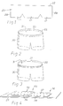
- Figure 1 is a schematic representation of a flat garment blank for forming a garment having a waist opening;
- Figure 2 is a schematic view of the blank of Figure 1 folded to form a garment;
- Figure 3 is a schematic view similar to Figure 2 showing an elasticated band attached to the waist opening;
- Figure 4 is a part schematic view of the garment of Figure 3 showing the join of the waist band;
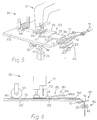
- Figure 5 is a perspective view of an apparatus according to the present invention;
- Figure 6 is a diagrammatic representation of the apparatus shown in Figure 5.
- Referring to Figures 1 to 4, there is shown a
garment blank 20 for forming a pair of shorts such as boxer shorts. The blank 20 is cut from a desirable material, preferably a woven fabric and hasleg forming portions 21 and a waist opening formingedge portion 22. - To form the garment, the blank 20 is folded to bring opposed end edges 26 into contact and the
edges 26 are joined together by sewing, usually by an overlock machine, to produce aseam 30. - The garment now has a
waist opening 31 and in accordance with the present invention, anelasticated band 32 is secured in face to face contact to amarginal portion 33 of the garment surrounding thewaist opening 31. Theband 32 is secured to the garment whilst in a tensioned condition (i.e. stretched condition) so that on relaxation, the fabric of themarginal portion 33 is ruched thereby enabling the band to stretch when the garment is being worn. - As shown more clearly in Figure 4, the
band 32 is secured to the garment blank such that oneend portion 35 overlies and is in face to face contact with theother end portion 36. Preferably, as shown in Figure 4, theband 32 is secured to the fabric by a pair of lines ofstitching end portions end portions join 40 at the opposed ends of the band is relatively flat. It will be appreciated that any desired number of longitudinally extending lines of stitching may be provided for securing the band to the garment. - The
end portion 35 is preferably applied and secured whilst in a tensioned condition such that theelasticated band 32 provides elastication around the entire periphery of thewaist opening 31. - Apparatus for applying the
elasticated band 32 to themarginal portion 33 surrounding theopening 31 is illustrated in Figures 5 and 6. - The
apparatus 50 includes asewing station 51 at which theband 32 is secured to themarginal portion 33. In the illustrated embodiment thesewing station 51 is defined by a sewing machine including twin needles 53, aplatform 55 and apresser foot 56. Feed dogs (not shown) are located beneath thepresser foot 56 for feeding the marginal portion and band past theneedles 53. - Downstream of the
sewing station 51 is atension roller 59 which is driven by the sewing machine in synchronism with the feed dogs. The purpose of theroller 59 is to maintain the band located between itself and the sewing needles 56 in a stretched condition so as to enable satisfactory stitching to be achieved. The rate of feed of theroller 59 and the feed dogs is therefore preferably the same. Theroller 59 is located above theplatform 55 so as to define a nipregion 60 therebetween for engaging the marginal portion and band. Theroller 59 preferably has a periphery adapted to frictionally engage the fabric passing through the nip region. Thus, the periphery may be provided with ribs and/or be formed from a material having a high co-efficient of friction. - On the upstream side of the sewing machine, the
band 32 is positively fed from a continuous length-supply bymetering device 62 having a pair of niprollers 63. - The nip
rollers 63 are preferably driven by an electric stepper motor (not shown) which is controllable to provide the desired tension. The motor is arranged to drive the rollers in a clockwise or anti-clockwise direction to increase or decrease tension in the band being applied to the sewing machine. During sewing, the motor is controlled to rotate the rollers in synchronism with the feed of the sewing machine in order to maintain the desired tension. - In order to form the
join 40 it is necessary to sever theband 32 from its supply whilst maintaining tension within the band as it passes through thesewing station 51. - This is achieved by the provision of a severing means 70 located between the
sewing station 51 and metering device 61 and atension holder 80 located between the cutting means 70 and thesewing station 51. - The
tension holder 80 is preferably in the form of amovable clamp head 82 located above theplatform 55. Theclamp head 82 is movable between a band engaged position whereat theclamp head 82 in co-operation with theplatform 55 grips theband 32 and a band disengaged position whereat theclamp head 82 is spaced from the platform so as not to grip the band. Preferably, theclamp head 82 is in the form of a recessedplate 84 which defines agrip edge 85 at one end for engaging theband 32. Accordingly, it is possible for thegrip edge 85 to be located in close proximity to thepresser foot 56 at thesewing station 51. - The
plate 84 is fixedly mounted on apivoting shaft 88 which is biased by for example aspring 83 in one direction for moving the plate to the disengaged position and which is moved in the opposite direction by apneumatic piston 89 operating on alever 90 fixed toshaft 88. By suitable adjustment of the fluid pressure applied topiston 89 it is possible to vary the pressure applied on the band by thegrip edge 85 and thereby control the tension applied to the band. This tension is chosen to be the same as that applied by themetering device 62. - The severing means 70 is preferably in the form of a
movable blade 71 which is pivotally mounted at one end and which co-operates with astatic blade 72 for severing theband 32. Thestatic blade 72 includes aslit 73 through which the band is guided and theblade 71 is preferably moved across thestatic blade 72 in scissor-like fashion by apneumatic piston 75 to co-operate with an opposed edge of the slit to sever the band. - In order to obtain a clean cut through the
band 32 so as to produce a neat square end edge it is necessary to cut theband 32 whilst it is in a relaxed condition. - Accordingly, when it is desired to sever the
band 32, feeding of theband 32 andmarginal portion 33 is stopped by simultaneously stopping the sewing machine. Theband 33 is now static but still held under tension between the sewing station and themetering device 62. -
Clamp 82 is now operated to move to its band engaged position and themetering device 62 is operated to feedband 32. Theband 32 between theclamp 82 and themetering device 62 is now fully relaxed and theband 32 between theclamp 82 andfeed roller 59 is still held under tension. The severing means 70 is now operated to sever theband 32. After severance, the sewing machine is operated causing theband 32 to be pulled through theclamp 82, the drag imposed on theband 32 by theclamp 82 serving to maintain the desired tension in the band. - Eventually, the end of the
band 32 emerges from theclamp 82 and as a consequence the length of the band in between thepresser foot 56 and the clamp contracts before being sewn. The point at which this happens is chosen such that thejoin 40 has already been made so that elastication around the waist opening is not affected. The length of band released from theclamp 82 is relatively short since thegrip edge 85 is located in close proximity to the presser foot and so does not present a problem for correct guiding to the sewing machine. - In order to provide positive guiding of the band upstream of the
grip edge 85 after severance, astatic guide plate 95 is provided. Theguide plate 95 extends within the recess 84a ofclamp plate 84 up to close proximity with thegrip edge 85. Theguide plate 95 includes achannel 96 which is preferably of the same width as the band when relaxed. In this way the band is positively guided along both edges. It is envisaged thatdifferent guide plates 95 would be provided having differing widths of channel in order to accommodate different widths of band. - The
clamp plate 84 and guideplate 95 also serve as a support surface for the marginal portion for shielding the marginal portion from the band until reaching the sewing station. - The sequence of operation is as follows:
The cycle is started by an operative back-treadling the sewing machine causing thepresser foot 56 and theroller 59 to be raised. - The operative inserts the garment over the band, drops the
presser foot 56, sews a pre-set number of stitches, typically two or three, after which theroller 59 drops automatically, and themetering device 62 automatically reverses to apply the pre-programmed tension to the band so that the ruched effect can be achieved. If desired, a non-ruched or flat area can be incorporated into the band. This is achieved by themetering device 62 over-feeding the elastic material. To return to the ruched effect, themetering device 62 then reverses again until the pre-programmed tension is applied. - The operative then sews to the cutting position and stops, at which point the
clamp 82 automatically drops onto the band and then the operator operates a control to cause themetering device 62 to release the tension, and simultaneously causes both theclamp 82 to be retained in the engaged position and the cutter to operate. The sequence is then completed by the operative sewing to the cut end of the band and back-treadling to remove the garment and thereby re-start the sequence, by automatically feeding in the band (elastic) to the presser foot. - Sequencing control of the
clamp 82,metering device 62 andcutter 70 is achieved via a programmable electronic control means (not shown) which senses the motor position of the sensing machine via an encoder. - Using the above invention as a basis, further refinements can be applied to produce other garments for use in leisure wear and normal dress.
- A garment with an elasticated band attached may be folded about the lower edge of the elasticated band and the elasticated band secured, most conveniently by a seam covering machine, in face to face contact to a further marginal portion of the garment to form a tunnelled waistband. Seam covering is a type of stitching used in the garment industry in which two parallel rows of stitching are continuously looped by a third covering thread so that a multiplicity of short lengths of thread extend between the two parallel rows of stitching. The rows of stitching applied during the elastication process prevent the elastic material from twisting within the tunnel.
- An inner lining material may be attached during the elastication process. The lining can be attached with one or more rows of stitching, then pushed down into the garment and seam covered, if required.
- Also, using the apparatus of the invention, discrete lengths of elastic material may be attached to any portion of a garment rather than using an entire loop or length of elastic material. The discrete length can be controlled under tension by the
tension holder 80. In this way, elastication can be applied to only the portion or portions of the garment where it is required, thus resulting in a saving of elastic material. - It will of course be understood that the invention is not limited to the specific details described herein, which are given by way of example only, and that various modifications and alterations are possible within the scope of the invention as defined in the appended claims.
Claims (15)
- A method of forming an elasticated portion in a garment, the method comprising securing one end of a length of elastic material in face to face contact to a marginal portion of the garment material, progressively securing the length whilst under tension along the portion of the garment material, severing the length of elastic material from its supply so that a finite length of elastic is applied to the garment material, and holding under tension the unsecured portion of the finite length whilst it is being secured to the garment material.
- A method as claimed in Claim 1, including feeding the length of elastic material to lie on or under the garment material and holding the cut end of the supply of elastic material for use with a subsequent piece of garment material.
- A method as claimed Claim 1 or Claim 2, including metering the length of elastic material from beneath the securing area.
- A method as claimed in any one of Claims 1 to 3, including forming an opening in a substantially completed garment, securing one end of the length of elastic material in face to face contact to a marginal portion of the garment surrounding the opening, severing the length of elastic material to form a finite length and securing the finite length under tension to the garment until a portion of the finite length of elastic material, including the other end, overlaps said one end to provide an elasticated portion in the form of an elasticated band.
- Apparatus for applying elastic material to a portion of garment material comprising securing means, means for feeding a strip of elastic material to lie on or under the garment material to enable the elastic material to be progressively secured by the securing means in face to face contact to a marginal portion of the garment material until a required length of elastic material is secured to the garment material, a cutting device for cutting the elastic material from its supply to form a finite length, and a tension holder for holding the unsecured portion of the cut finite length under tension whilst the securing operation is being completed.
- Apparatus as claimed in Claim 5, including programmable electronic metering means for metering the elastic material from beneath the securing means and for holding the cut end of the supply of elastic material for use with the subsequent piece of garment material.
- Apparatus as claimed in Claims 5 or 6, which includes feed means for simultaneously feeding the length of elastic material and garment marginal portion passed the securing means, the feed means being arranged to pull the elastic material past the tension holder located immediately upstream of the securing means, the tension holder being engageable with the length of elastic material to resist its longitudinal movement and thereby generate tension in the length of elastic material between the feed means and the tension holder so that the the length of elastic material is secured to the marginal portion under tension.
- Apparatus as claimed in any one of Claims 5 to 7, in which the length of elastic material is supplied to the securing means from a continuous length stored for example on a reel, the metering means being provided upstream of the tension holder and arranged positively to feed the continuous length of elastic material toward the securing means at a slower rate than said feed means to thereby tension the length of elastic material located between the metering means and the feed means, the tension holder being selectively actuatable to grip or release the length of elastic material to isolate respectively the metering means from the feed means or enable the metering means to apply tension to the length of elastic material.
- Apparatus as claimed in Claim 8, in which the tension holder comprises a movable clamp head and a platform, the clamp head being movable towards and away from the platform respectively, between an elastic gripping position and an elastic release portion.
- Apparatus as claimed in Claim 9, in which the clamp head is in the form of a recessed plate which defines a grip edge at one end for engaging the elastic material, the plate being fixedly mounted on a pivotable shaft having biassing means for moving the plate to the release position and piston means operable against a lever coupled to the shaft for moving the plate to the gripping position.
- Apparatus as claimed in Claim 10, in which a static guide plate having a channel is provided for guiding the edges of the length of elastic material toward the grip edge, the guide plate extending within the recess of the clamp plate up to close proximity with the grip edge.
- A garment having an elasticated opening defined by a band of elastic material secured by one or more longitudinally extending lines of stitching in face to face contact with a marginal portion of the garment surrounding the opening, the band having a join region defined by a first end secured in face to face contact to the marginal portion and a second end which overlaps and is secured in face to face contact to the band adjacent the first end and additionally to the garment, whereby the join region has at least two overlapping lines of stitching secured to the garment material.
- A garment as claimed in Claim 12, in which the garment is folded about the lower edge of the elasticated band and the elasticated band is secured in face to face contact to a further marginal portion of the garment material to form a tunnelled waistband.
- A garment as claimed in either Claim 12 or 13, having a lining secured thereto with the band of elastic material.
- A garment having an elasticated portion defined by a finite length of elastic material secured by one or more longitudinally extending lines of stitching in face to face contact to a marginal portion of the garment material, the finite length of elastic material being secured to the garment material under tension between its first end and its remote second end.
Applications Claiming Priority (4)
| Application Number | Priority Date | Filing Date | Title |
|---|---|---|---|
| IE281190 | 1990-08-03 | ||
| IE281190 | 1990-08-03 | ||
| GB9111549 | 1991-05-29 | ||
| GB919111549A GB9111549D0 (en) | 1991-05-29 | 1991-05-29 | Band seamer |
Publications (1)
| Publication Number | Publication Date |
|---|---|
| EP0476818A1 true EP0476818A1 (en) | 1992-03-25 |
Family
ID=26298970
Family Applications (1)
| Application Number | Title | Priority Date | Filing Date |
|---|---|---|---|
| EP91307137A Withdrawn EP0476818A1 (en) | 1990-08-03 | 1991-08-02 | Improvements in a method of and apparatus for applying elastic material to garments |
Country Status (2)
| Country | Link |
|---|---|
| EP (1) | EP0476818A1 (en) |
| JP (1) | JPH04357995A (en) |
Cited By (10)
| Publication number | Priority date | Publication date | Assignee | Title |
|---|---|---|---|---|
| GB2260144B (en) * | 1991-10-03 | 1995-12-06 | El Sew Con Ltd | Control system for elastic or trims |
| US5602747A (en) * | 1995-01-31 | 1997-02-11 | Kimberly-Clark Corporation | Controlling web tension by actively controlling velocity of dancer roll |
| US6314333B1 (en) | 1998-07-03 | 2001-11-06 | Kimberly-Clark Worldwide, Inc. | Method and apparatus for controlling web tension by actively controlling velocity and acceleration of a dancer roll |
| DE10023537A1 (en) * | 2000-05-13 | 2001-11-22 | Schips Ag Naehautomation Tueba | Sewing machine for stitching an elastic band has a supply and a feed/cutter unit which moves in and out of the stitching zone to feed the band to the presser foot and cut the stitched band |
| US6473669B2 (en) | 1998-07-03 | 2002-10-29 | Kimberly-Clark Worldwide, Inc. | Controlling web tension, and accumulating lengths of web, by actively controlling velocity and acceleration of a festoon |
| US6856850B2 (en) | 1998-07-03 | 2005-02-15 | Kimberly Clark Worldwide, Inc. | Controlling web tension, and accumulating lengths of web, using a festoon |
| CN102899816A (en) * | 2011-07-26 | 2013-01-30 | 吕学忠 | Elastic web tensioning device |
| TWI640667B (en) * | 2017-06-20 | 2018-11-11 | 高林股份有限公司 | Cloth feeding device for automatic sewing equipment |
| US10834974B2 (en) | 2010-12-31 | 2020-11-17 | 0912139 B.C. Ltd. | Garments for men |
| US11272744B2 (en) | 2020-02-25 | 2022-03-15 | 0912139 B.C. Ltd. | Male garment |
Citations (7)
| Publication number | Priority date | Publication date | Assignee | Title |
|---|---|---|---|---|
| GB1041071A (en) * | 1963-04-10 | 1966-09-01 | R & W H Symington And Company | Improvements in or relating to attaching elastic strips to textile material |
| GB1406822A (en) * | 1972-06-21 | 1975-09-17 | Automatic Braiding Co | Garments |
| US3964410A (en) * | 1975-01-24 | 1976-06-22 | Boser Ronald J | Elastic inserter for a sewing machine |
| GB1445391A (en) * | 1973-04-02 | 1976-08-11 | Automatic Braiding Co | Manufacture of garments |
| EP0165380A1 (en) * | 1984-03-20 | 1985-12-27 | Helmut Schips | Sewing machine |
| DE3638989C1 (en) * | 1986-11-14 | 1988-02-11 | Texpa Arbter Maschb Gmbh | Apparatus for making at least one hem on a cloth material having a sewn-in tape, especially rubber tape |
| EP0279749A2 (en) * | 1987-02-17 | 1988-08-24 | Denis Plante | Elastic band feeding and tensioning mechanism for a sewing machine |
-
1991
- 1991-08-02 EP EP91307137A patent/EP0476818A1/en not_active Withdrawn
- 1991-08-02 JP JP21639591A patent/JPH04357995A/en not_active Withdrawn
Patent Citations (7)
| Publication number | Priority date | Publication date | Assignee | Title |
|---|---|---|---|---|
| GB1041071A (en) * | 1963-04-10 | 1966-09-01 | R & W H Symington And Company | Improvements in or relating to attaching elastic strips to textile material |
| GB1406822A (en) * | 1972-06-21 | 1975-09-17 | Automatic Braiding Co | Garments |
| GB1445391A (en) * | 1973-04-02 | 1976-08-11 | Automatic Braiding Co | Manufacture of garments |
| US3964410A (en) * | 1975-01-24 | 1976-06-22 | Boser Ronald J | Elastic inserter for a sewing machine |
| EP0165380A1 (en) * | 1984-03-20 | 1985-12-27 | Helmut Schips | Sewing machine |
| DE3638989C1 (en) * | 1986-11-14 | 1988-02-11 | Texpa Arbter Maschb Gmbh | Apparatus for making at least one hem on a cloth material having a sewn-in tape, especially rubber tape |
| EP0279749A2 (en) * | 1987-02-17 | 1988-08-24 | Denis Plante | Elastic band feeding and tensioning mechanism for a sewing machine |
Cited By (12)
| Publication number | Priority date | Publication date | Assignee | Title |
|---|---|---|---|---|
| GB2260144B (en) * | 1991-10-03 | 1995-12-06 | El Sew Con Ltd | Control system for elastic or trims |
| US5602747A (en) * | 1995-01-31 | 1997-02-11 | Kimberly-Clark Corporation | Controlling web tension by actively controlling velocity of dancer roll |
| US5659229A (en) * | 1995-01-31 | 1997-08-19 | Kimberly-Clark Worldwide, Inc. | Controlling web tension by actively controlling velocity of dancer roll |
| US6314333B1 (en) | 1998-07-03 | 2001-11-06 | Kimberly-Clark Worldwide, Inc. | Method and apparatus for controlling web tension by actively controlling velocity and acceleration of a dancer roll |
| US6473669B2 (en) | 1998-07-03 | 2002-10-29 | Kimberly-Clark Worldwide, Inc. | Controlling web tension, and accumulating lengths of web, by actively controlling velocity and acceleration of a festoon |
| US6856850B2 (en) | 1998-07-03 | 2005-02-15 | Kimberly Clark Worldwide, Inc. | Controlling web tension, and accumulating lengths of web, using a festoon |
| DE10023537A1 (en) * | 2000-05-13 | 2001-11-22 | Schips Ag Naehautomation Tueba | Sewing machine for stitching an elastic band has a supply and a feed/cutter unit which moves in and out of the stitching zone to feed the band to the presser foot and cut the stitched band |
| US10834974B2 (en) | 2010-12-31 | 2020-11-17 | 0912139 B.C. Ltd. | Garments for men |
| CN102899816A (en) * | 2011-07-26 | 2013-01-30 | 吕学忠 | Elastic web tensioning device |
| CN102899816B (en) * | 2011-07-26 | 2014-05-07 | 吕学忠 | Elastic web tensioning device |
| TWI640667B (en) * | 2017-06-20 | 2018-11-11 | 高林股份有限公司 | Cloth feeding device for automatic sewing equipment |
| US11272744B2 (en) | 2020-02-25 | 2022-03-15 | 0912139 B.C. Ltd. | Male garment |
Also Published As
| Publication number | Publication date |
|---|---|
| JPH04357995A (en) | 1992-12-10 |
Similar Documents
| Publication | Publication Date | Title |
|---|---|---|
| US5040473A (en) | Method of, and apparatus for, processing textile material webs, particularly for manufacturing quilts and the like | |
| US5370071A (en) | Lap seamer device for sewing machine | |
| US4703706A (en) | Elastic band feeding and tensioning mechanism for a sewing machine | |
| US4290376A (en) | Auxiliary transport device for sewing machines | |
| EP0476818A1 (en) | Improvements in a method of and apparatus for applying elastic material to garments | |
| US4739718A (en) | Method and apparatus for sewing a waistband and applying it to a garment | |
| US3780679A (en) | Apparatus for producing endless bands | |
| US2467281A (en) | Method of and apparatus for handling tubular knitted fabric | |
| US2011512A (en) | Method of binding the edges of knitted fabrics | |
| KR920008100B1 (en) | Method and apparatus for sewing fly pieces to a slide fastner chain | |
| US4233916A (en) | Process and apparatus for producing continuous embroidered fabrics | |
| US3893402A (en) | Sewing apparatus | |
| CN107687050B (en) | Method for making trousers | |
| US2821385A (en) | Belt making machine | |
| JPH0262273B2 (en) | ||
| JP4022043B2 (en) | Sewing machine and sewing method capable of releasing tension string of passage made by sewing seam | |
| US4314516A (en) | Workpiece guide for sewing machines | |
| TW201812132A (en) | Sewing machine for sewing long band-shaped material | |
| US4524706A (en) | Trim attaching machine and method | |
| US3922978A (en) | Folding apparatus for a sewing machine | |
| JP3735768B2 (en) | sewing machine | |
| US5072677A (en) | Enclosing elastic in a fabric | |
| US3128730A (en) | Sewing machine for feeding, sewing and cutting sections of tape | |
| TW201915252A (en) | Sewing machine, sewing device, and sewing method | |
| US6044783A (en) | Method and apparatus for automatically finishing the end of a binding strip |
Legal Events
| Date | Code | Title | Description |
|---|---|---|---|
| PUAI | Public reference made under article 153(3) epc to a published international application that has entered the european phase |
Free format text: ORIGINAL CODE: 0009012 |
|
| AK | Designated contracting states |
Kind code of ref document: A1 Designated state(s): AT BE CH DE DK ES FR GB GR IT LI LU NL SE |
|
| 17P | Request for examination filed |
Effective date: 19920925 |
|
| 17Q | First examination report despatched |
Effective date: 19940322 |
|
| STAA | Information on the status of an ep patent application or granted ep patent |
Free format text: STATUS: THE APPLICATION IS DEEMED TO BE WITHDRAWN |
|
| 18D | Application deemed to be withdrawn |
Effective date: 19941003 |