EP0476357A1 - Magnetkupplung - Google Patents
Magnetkupplung Download PDFInfo
- Publication number
- EP0476357A1 EP0476357A1 EP91114218A EP91114218A EP0476357A1 EP 0476357 A1 EP0476357 A1 EP 0476357A1 EP 91114218 A EP91114218 A EP 91114218A EP 91114218 A EP91114218 A EP 91114218A EP 0476357 A1 EP0476357 A1 EP 0476357A1
- Authority
- EP
- European Patent Office
- Prior art keywords
- magnets
- split plate
- magnetic coupling
- magnetic
- coupling
- Prior art date
- Legal status (The legal status is an assumption and is not a legal conclusion. Google has not performed a legal analysis and makes no representation as to the accuracy of the status listed.)
- Withdrawn
Links
- 230000008878 coupling Effects 0.000 title claims abstract description 34
- 238000010168 coupling process Methods 0.000 title claims abstract description 34
- 238000005859 coupling reaction Methods 0.000 title claims abstract description 34
- 238000005096 rolling process Methods 0.000 claims description 7
- 230000005540 biological transmission Effects 0.000 claims 1
- 238000000926 separation method Methods 0.000 claims 1
- 230000006378 damage Effects 0.000 description 4
- 238000010276 construction Methods 0.000 description 1
- 238000011109 contamination Methods 0.000 description 1
- 238000003912 environmental pollution Methods 0.000 description 1
- 238000004519 manufacturing process Methods 0.000 description 1
- 238000000034 method Methods 0.000 description 1
- 238000005457 optimization Methods 0.000 description 1
- 238000005192 partition Methods 0.000 description 1
Images
Classifications
-
- H—ELECTRICITY
- H02—GENERATION; CONVERSION OR DISTRIBUTION OF ELECTRIC POWER
- H02K—DYNAMO-ELECTRIC MACHINES
- H02K49/00—Dynamo-electric clutches; Dynamo-electric brakes
- H02K49/10—Dynamo-electric clutches; Dynamo-electric brakes of the permanent-magnet type
- H02K49/102—Magnetic gearings, i.e. assembly of gears, linear or rotary, by which motion is magnetically transferred without physical contact
-
- H—ELECTRICITY
- H02—GENERATION; CONVERSION OR DISTRIBUTION OF ELECTRIC POWER
- H02K—DYNAMO-ELECTRIC MACHINES
- H02K5/00—Casings; Enclosures; Supports
- H02K5/04—Casings or enclosures characterised by the shape, form or construction thereof
- H02K5/12—Casings or enclosures characterised by the shape, form or construction thereof specially adapted for operating in liquid or gas
- H02K5/128—Casings or enclosures characterised by the shape, form or construction thereof specially adapted for operating in liquid or gas using air-gap sleeves or air-gap discs
Definitions
- the invention relates to a magnetic coupling according to the preamble of the main claim.
- Such magnetic couplings are known from the article "Recoma standard couplings", by D. Weinmann, in Technische Rundschau, Bern, No. 48, 1980, page 27. They are characterized by a hermetically sealed split plate arranged between the coupling halves, against which the magnets on the drive and driven side perform relative movements.
- the split plate is a disk-shaped or pot-shaped or tubular component made of non-magnetizable material.
- a stable mounting of the rotating parts is one of the main requirements for a safe function of this type of coupling. Because contact between the rotating part and the stationary split plate could result in its destruction. Since this type of construction is often used for the conveyance of dangerous media, which usually circulate in a hermetically sealed circuit, destruction of the can and the resulting environmental pollution must be avoided under all circumstances.
- one part of the magnetic coupling usually the part to be driven, is arranged on the side exposed to the dangerous medium, its bearing parts are located within the medium and their function is endangered by contamination. Furthermore, there is a risk that hard foreign bodies within the medium can cause damage to the medium-side gap between the driven part of the magnetic coupling and the split plate.
- the invention has for its object to minimize the design gap between the magnets and the split plate. This object is achieved in accordance with the characterizing part of the main claim.
- This magnetic coupling system consists of mutually opposing, attracting magnets lying directly on the split plate. The magnets roll directly on the split plate and, according to a torque to be transmitted, several magnet pairs are arranged next to one another or distributed over the circumference. The magnets are rotatably mounted in the coupling halves and have a rollable cross section. The required number and dimensions of the magnets can be determined with the aid of known optimization processes.
- One embodiment of the invention provides that the magnets are provided with pole pieces that can be rolled off on the split plate.
- the magnets are provided with pole shoes that increase the magnetic forces in the area of their poles.
- the pole pieces of the individual magnet pairs then roll directly on the split plate.
- Another embodiment of the invention provides that the magnets in their driving and / or driven coupling parts have a bearing with a large bearing clearance.
- the magnets are designed as permanent magnets, as is also the case with the known magnetic clutches to date, and magnets rolling on a flat split plate are conical.
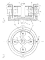
- the magnetic coupling shown by way of example in FIG. 1 belongs to the design of the central rotary couplings and consists of a driving shaft (1), at the end of which a basket (2) is attached, on which a plurality of rollable magnets (3) are arranged. These magnets are stored within the basket (2) with play, so that they reliably rest against the split plate (4), which is designed here as a canned pot, and thus can follow any deviations from an ideal circular shape. With each magnet (3) there is an opposing magnet (5) on the other side of the split plate (4), here on the inside of the canned pot. The poles of the magnets are marked with N and S and are arranged so that they attract each other.
- the magnet ends are used to reinforce the magnetic forces equipped with pole pieces (6), which lie directly on the split plate (4).
- the magnetic lines (7) run from the north side of a magnet (3) through the pole piece (6) into the split plate (4), onto the opposite pole piece (6) of the south side of the other magnet (5), from there over the pole piece of the north side again in the split plate (4) and in the south-facing pole piece of the outer magnet (3).
- the magnets (5) rolling within the split plate (4) designed as a split tube pot are also radially resiliently mounted in the driven part (8) of the coupling, in order to ensure secure contact with the split plate (4) at all times.
- the inner part (8) of the coupling, the shaft (9) of which can be part of a pump, is usually filled with the medium to be pumped.
- this solution has the advantage that any foreign bodies in the medium are either swept aside by the flow movement within the space (10) and thus do not damage the split plate (4) or that the flexibly arranged magnets (3, 5 ) or their pole pieces (6) simply roll over a foreign body and either push aside or crush. With the help of an appropriate choice of material or a corresponding material treatment, it is ensured that the magnets (3) and / or pole shoes (6) rolling on the split plate (4) do not cause any change in shape of the split plate.
- Fig. 2 shows a plan view from which it can be seen that a total of four magnet pairs are used in the example shown here, which cause the rotary movement of the driving shaft (1) on the shaft (9) to be driven. Any non-roundness of the containment can can be easily followed due to the increased bearing play of the rotatable magnets (3, 5).
- the shaft (9) to be driven can be stably supported in a simple manner and with conventional means in a partition wall, not shown here.
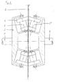
- Fig. 3 shows an embodiment in which an end rotary coupling is used.
- the magnets (3, 5) rolling here on the split plate (4) are provided with pole shoes (6) in a conical shape, which are dimensioned such that a smooth rolling movement is possible without a relative movement between the magnets and the split plate.
- the endeavor of the magnets to move outwards as a result of the centrifugal forces can be prevented with the aid of a corresponding bearing in the driving and / or driven part or with the aid of a thrust collar.
Landscapes
- Engineering & Computer Science (AREA)
- Power Engineering (AREA)
- Magnetic Bearings And Hydrostatic Bearings (AREA)
- Rolling Contact Bearings (AREA)
Applications Claiming Priority (2)
| Application Number | Priority Date | Filing Date | Title |
|---|---|---|---|
| DE19904029182 DE4029182C1 (enExample) | 1990-09-14 | 1990-09-14 | |
| DE4029182 | 1990-09-14 |
Publications (1)
| Publication Number | Publication Date |
|---|---|
| EP0476357A1 true EP0476357A1 (de) | 1992-03-25 |
Family
ID=6414242
Family Applications (1)
| Application Number | Title | Priority Date | Filing Date |
|---|---|---|---|
| EP91114218A Withdrawn EP0476357A1 (de) | 1990-09-14 | 1991-08-24 | Magnetkupplung |
Country Status (2)
| Country | Link |
|---|---|
| EP (1) | EP0476357A1 (enExample) |
| DE (1) | DE4029182C1 (enExample) |
Cited By (7)
| Publication number | Priority date | Publication date | Assignee | Title |
|---|---|---|---|---|
| US5569111A (en) * | 1994-10-11 | 1996-10-29 | The United States Of America As Represented By The Secretary Of The Navy | Permanent magnet torque/force transfer apparatus |
| WO1999063648A1 (en) * | 1998-05-29 | 1999-12-09 | Joseph Peter William Baker | Motion transmission devices |
| WO2000035068A1 (en) * | 1998-12-10 | 2000-06-15 | Joseph Peter William Baker | Barrier apparatus |
| CN1299019C (zh) * | 2005-04-14 | 2007-02-07 | 西安理工大学 | 真空系统非接触挠性磁联轴器 |
| EP1648079A3 (en) * | 2004-10-14 | 2009-08-05 | MARCHESINI GROUP S.p.A. | System for transmitting motion between means separated by a wall |
| ITPD20130219A1 (it) * | 2013-08-02 | 2015-02-03 | Paolo Fior | Dispositivo trasformatore di energia cinetica |
| CN104653747A (zh) * | 2013-11-20 | 2015-05-27 | 鸿富锦精密工业(深圳)有限公司 | 增减速装置 |
Families Citing this family (3)
| Publication number | Priority date | Publication date | Assignee | Title |
|---|---|---|---|---|
| DE102013006322B4 (de) * | 2013-04-12 | 2015-10-08 | Createc Fischer & Co. Gmbh | Magnetischer Antrieb für Vakuumanlagen |
| DE102015002372A1 (de) | 2015-02-25 | 2016-08-25 | Berliner Glas Kgaa Herbert Kubatz Gmbh & Co | Optische Einrichtung mit magnetischem Antrieb, insbesondere für ein Endoskop |
| DE102018009178A1 (de) | 2018-11-22 | 2019-06-27 | Eckhard P. Kaufmann | Eigengelagerte Magnetkupplung mit intern kompensierten Axial-und Radialkräften |
Citations (2)
| Publication number | Priority date | Publication date | Assignee | Title |
|---|---|---|---|---|
| EP0039777A2 (de) * | 1980-05-13 | 1981-11-18 | Thyssen Edelstahlwerke AG | Synchronkupplung |
| DE3922426A1 (de) * | 1988-09-19 | 1990-03-22 | Sulzer Ag | Magnetkupplung fuer rotierende prozesspumpen |
-
1990
- 1990-09-14 DE DE19904029182 patent/DE4029182C1/de not_active Expired - Lifetime
-
1991
- 1991-08-24 EP EP91114218A patent/EP0476357A1/de not_active Withdrawn
Patent Citations (2)
| Publication number | Priority date | Publication date | Assignee | Title |
|---|---|---|---|---|
| EP0039777A2 (de) * | 1980-05-13 | 1981-11-18 | Thyssen Edelstahlwerke AG | Synchronkupplung |
| DE3922426A1 (de) * | 1988-09-19 | 1990-03-22 | Sulzer Ag | Magnetkupplung fuer rotierende prozesspumpen |
Non-Patent Citations (1)
| Title |
|---|
| SOVIET INVENTIONS ILLUSTRATED Section EI, Week 8946, 3. Januar 1990 Derwent Publications Ltd., London, GB; Class X, AN 89-338397 & SU-A-1 480 027 (N-W CORRESPONDENCE POLY) 15. Mai 1989 * |
Cited By (8)
| Publication number | Priority date | Publication date | Assignee | Title |
|---|---|---|---|---|
| US5569111A (en) * | 1994-10-11 | 1996-10-29 | The United States Of America As Represented By The Secretary Of The Navy | Permanent magnet torque/force transfer apparatus |
| WO1999063648A1 (en) * | 1998-05-29 | 1999-12-09 | Joseph Peter William Baker | Motion transmission devices |
| US6462447B1 (en) * | 1998-05-29 | 2002-10-08 | Joseph Peter William Baker | Motion transmission devices |
| WO2000035068A1 (en) * | 1998-12-10 | 2000-06-15 | Joseph Peter William Baker | Barrier apparatus |
| EP1648079A3 (en) * | 2004-10-14 | 2009-08-05 | MARCHESINI GROUP S.p.A. | System for transmitting motion between means separated by a wall |
| CN1299019C (zh) * | 2005-04-14 | 2007-02-07 | 西安理工大学 | 真空系统非接触挠性磁联轴器 |
| ITPD20130219A1 (it) * | 2013-08-02 | 2015-02-03 | Paolo Fior | Dispositivo trasformatore di energia cinetica |
| CN104653747A (zh) * | 2013-11-20 | 2015-05-27 | 鸿富锦精密工业(深圳)有限公司 | 增减速装置 |
Also Published As
| Publication number | Publication date |
|---|---|
| DE4029182C1 (enExample) | 1992-04-09 |
Similar Documents
| Publication | Publication Date | Title |
|---|---|---|
| AT515555B1 (de) | Magnetkupplung | |
| DE3839731C2 (enExample) | ||
| DE4430853A1 (de) | Zentrifugal-Blutpumpe | |
| EP0563437B1 (de) | Anordnung zur konzentrischen Positionierung eines ersten Teiles relativ zu einem zweiten Teil, insbesondere einer Büchse gegenüber einer Welle | |
| DE69612834T2 (de) | Magnetische kupplung | |
| DE4029182C1 (enExample) | ||
| DE3136470A1 (de) | "differential mit zwei achsgleichen abtriebswellen" | |
| DE3842477A1 (de) | Magnetfluid-dichtungs-aufbau | |
| EP0040733A2 (de) | Generatorläufer, insbesondere Turbogeneratorläufer, mit supraleitender Erregerwicklung | |
| DE2205959A1 (de) | Pump- und Filtereinheit | |
| DE69708238T2 (de) | Dauermagnet Wirbelstrom Bremsgerät | |
| DE2136371A1 (de) | Magnetische lagerung von wellen oder dergl | |
| DE3135385A1 (de) | Plattenspeicher | |
| DE3117377A1 (de) | Verfahren und vorrichtung zum umwandeln einer antriebsbewegung | |
| DE3941444C2 (de) | Permanentmagnetantrieb für eine Pumpe, ein Rührwerk oder eine Armatur | |
| DE1766929B1 (de) | Anzeigevorrichtung zur ferneinstellung eines zeichens | |
| EP0088909A2 (de) | Vorrichtung zur Übertragung von Kräften | |
| DE4020726A1 (de) | Magnetlager | |
| DE3628961C1 (en) | Model rail-mounted vehicle | |
| DE112010001579T5 (de) | Kupplungseinrichtung | |
| DE3612167A1 (de) | Luefteranordnung, insbesondere zur kuehlung von wassergekuehlten verbrennungskraftmaschinen | |
| DE2136187A1 (de) | Elektromotor | |
| DE3509023C2 (enExample) | ||
| DE2264912A1 (de) | Kombiniertes axial-radial-lager | |
| DE3728868B4 (de) | Elektromotor mit relativ zueinander drehbar und axial verschiebbar gelagertem Rotor und Stator |
Legal Events
| Date | Code | Title | Description |
|---|---|---|---|
| PUAI | Public reference made under article 153(3) epc to a published international application that has entered the european phase |
Free format text: ORIGINAL CODE: 0009012 |
|
| AK | Designated contracting states |
Kind code of ref document: A1 Designated state(s): AT BE CH DE DK FR GB IT LI NL |
|
| 17P | Request for examination filed |
Effective date: 19920304 |
|
| 17Q | First examination report despatched |
Effective date: 19920803 |
|
| STAA | Information on the status of an ep patent application or granted ep patent |
Free format text: STATUS: THE APPLICATION IS DEEMED TO BE WITHDRAWN |
|
| 18D | Application deemed to be withdrawn |
Effective date: 19930816 |