EP0475918A2 - Elektronisches Steuerungssystem für hydrokinetisches Lastschaltgetriebe eines Kraftfahrzeuges - Google Patents
Elektronisches Steuerungssystem für hydrokinetisches Lastschaltgetriebe eines Kraftfahrzeuges Download PDFInfo
- Publication number
- EP0475918A2 EP0475918A2 EP91830371A EP91830371A EP0475918A2 EP 0475918 A2 EP0475918 A2 EP 0475918A2 EP 91830371 A EP91830371 A EP 91830371A EP 91830371 A EP91830371 A EP 91830371A EP 0475918 A2 EP0475918 A2 EP 0475918A2
- Authority
- EP
- European Patent Office
- Prior art keywords
- unit
- mcu
- pressure
- speed
- vehicle
- Prior art date
- Legal status (The legal status is an assumption and is not a legal conclusion. Google has not performed a legal analysis and makes no representation as to the accuracy of the status listed.)
- Withdrawn
Links
- 230000005540 biological transmission Effects 0.000 title claims abstract description 21
- 230000001970 hydrokinetic effect Effects 0.000 title claims description 8
- 230000006870 function Effects 0.000 claims description 52
- 239000012530 fluid Substances 0.000 claims description 48
- 230000000694 effects Effects 0.000 claims description 28
- 238000000034 method Methods 0.000 claims description 28
- 230000000979 retarding effect Effects 0.000 claims description 10
- 230000000994 depressogenic effect Effects 0.000 claims description 8
- 230000008859 change Effects 0.000 claims description 7
- 238000002485 combustion reaction Methods 0.000 claims description 5
- 230000001105 regulatory effect Effects 0.000 claims description 3
- 238000012545 processing Methods 0.000 claims description 2
- 230000001276 controlling effect Effects 0.000 claims 1
- 230000000737 periodic effect Effects 0.000 claims 1
- 230000007935 neutral effect Effects 0.000 description 9
- 230000015654 memory Effects 0.000 description 5
- 230000001133 acceleration Effects 0.000 description 3
- 238000012360 testing method Methods 0.000 description 3
- 230000004913 activation Effects 0.000 description 2
- 230000008901 benefit Effects 0.000 description 2
- 230000007423 decrease Effects 0.000 description 2
- 230000005355 Hall effect Effects 0.000 description 1
- 238000010276 construction Methods 0.000 description 1
- 238000012937 correction Methods 0.000 description 1
- 238000001514 detection method Methods 0.000 description 1
- 238000010586 diagram Methods 0.000 description 1
- 230000007717 exclusion Effects 0.000 description 1
- XDDAORKBJWWYJS-UHFFFAOYSA-N glyphosate Chemical compound OC(=O)CNCP(O)(O)=O XDDAORKBJWWYJS-UHFFFAOYSA-N 0.000 description 1
- 238000012423 maintenance Methods 0.000 description 1
- 230000007257 malfunction Effects 0.000 description 1
- 239000000463 material Substances 0.000 description 1
- 230000003287 optical effect Effects 0.000 description 1
- 238000012887 quadratic function Methods 0.000 description 1
- 230000009467 reduction Effects 0.000 description 1
- 230000004044 response Effects 0.000 description 1
- 239000007858 starting material Substances 0.000 description 1
- 230000002459 sustained effect Effects 0.000 description 1
Images


Classifications
-
- F—MECHANICAL ENGINEERING; LIGHTING; HEATING; WEAPONS; BLASTING
- F16—ENGINEERING ELEMENTS AND UNITS; GENERAL MEASURES FOR PRODUCING AND MAINTAINING EFFECTIVE FUNCTIONING OF MACHINES OR INSTALLATIONS; THERMAL INSULATION IN GENERAL
- F16H—GEARING
- F16H61/00—Control functions within control units of change-speed- or reversing-gearings for conveying rotary motion ; Control of exclusively fluid gearing, friction gearing, gearings with endless flexible members or other particular types of gearing
- F16H61/04—Smoothing ratio shift
- F16H61/06—Smoothing ratio shift by controlling rate of change of fluid pressure
- F16H61/061—Smoothing ratio shift by controlling rate of change of fluid pressure using electric control means
-
- F—MECHANICAL ENGINEERING; LIGHTING; HEATING; WEAPONS; BLASTING
- F16—ENGINEERING ELEMENTS AND UNITS; GENERAL MEASURES FOR PRODUCING AND MAINTAINING EFFECTIVE FUNCTIONING OF MACHINES OR INSTALLATIONS; THERMAL INSULATION IN GENERAL
- F16H—GEARING
- F16H61/00—Control functions within control units of change-speed- or reversing-gearings for conveying rotary motion ; Control of exclusively fluid gearing, friction gearing, gearings with endless flexible members or other particular types of gearing
- F16H61/0021—Generation or control of line pressure
-
- F—MECHANICAL ENGINEERING; LIGHTING; HEATING; WEAPONS; BLASTING
- F16—ENGINEERING ELEMENTS AND UNITS; GENERAL MEASURES FOR PRODUCING AND MAINTAINING EFFECTIVE FUNCTIONING OF MACHINES OR INSTALLATIONS; THERMAL INSULATION IN GENERAL
- F16H—GEARING
- F16H61/00—Control functions within control units of change-speed- or reversing-gearings for conveying rotary motion ; Control of exclusively fluid gearing, friction gearing, gearings with endless flexible members or other particular types of gearing
- F16H61/02—Control functions within control units of change-speed- or reversing-gearings for conveying rotary motion ; Control of exclusively fluid gearing, friction gearing, gearings with endless flexible members or other particular types of gearing characterised by the signals used
- F16H61/0202—Control functions within control units of change-speed- or reversing-gearings for conveying rotary motion ; Control of exclusively fluid gearing, friction gearing, gearings with endless flexible members or other particular types of gearing characterised by the signals used the signals being electric
- F16H61/0204—Control functions within control units of change-speed- or reversing-gearings for conveying rotary motion ; Control of exclusively fluid gearing, friction gearing, gearings with endless flexible members or other particular types of gearing characterised by the signals used the signals being electric for gearshift control, e.g. control functions for performing shifting or generation of shift signal
- F16H61/0246—Control functions within control units of change-speed- or reversing-gearings for conveying rotary motion ; Control of exclusively fluid gearing, friction gearing, gearings with endless flexible members or other particular types of gearing characterised by the signals used the signals being electric for gearshift control, e.g. control functions for performing shifting or generation of shift signal characterised by initiating reverse gearshift
-
- F—MECHANICAL ENGINEERING; LIGHTING; HEATING; WEAPONS; BLASTING
- F16—ENGINEERING ELEMENTS AND UNITS; GENERAL MEASURES FOR PRODUCING AND MAINTAINING EFFECTIVE FUNCTIONING OF MACHINES OR INSTALLATIONS; THERMAL INSULATION IN GENERAL
- F16H—GEARING
- F16H59/00—Control inputs to control units of change-speed-, or reversing-gearings for conveying rotary motion
- F16H59/02—Selector apparatus
- F16H59/08—Range selector apparatus
- F16H2059/088—Fast forward-reverse-sequence mode
Definitions
- the present invention relates to an electronic control system for a hydrokinetic transmission for a motor vehicle, particularly a lift truck, with an internal combustion engine the speed of rotation of which can be controlled by an accelerator.
- the invention relates to an electronic control system for a transmission including: a hydraulic converter, and a power-shift gearbox coupled to the output shaft of the converter and including a plurality of hydraulic clutches which are associated with the gears, which can be activated selectively by the manual operation of a selector, and which are controlled by a plurality of on-off enabling solenoid valves and an electrically-operated pressure-modulator connected to a source of pressurised fluid.
- the invention is intended, in particular, for a control system including: sensor means for supplying electrical signals indicative of the speeds of rotation of the input and output shafts of the hydraulic converter, of the speed and sense of rotation of the output shaft of the gearbox, and of the positions of the engine accelerator and the selector, and an electronic processing and control unit which is arranged to pilot the pressure modulator and the enabling solenoid valves in a predetermined manner in dependence on the signals supplied thereto by the sensor means.
- An object of the present invention is to provide an electronic control system for a hydrokinetic transmission for a motor vehicle with an internal combustion engine, particularly a lift truck, which enables the operation described above to be carried out automatically without the need for the user to have any particular skill or familiarity with the vehicle.
- an electronic control system for a hydrokinetic transmission of the type specified above the main characteristic of which lies in the fact that the system also includes a manual or pedal-operated control connected to the electronic unit, and in that the unit is arranged to effect an automatic control procedure for advancing the vehicle slowly at a predetermined speed when the sensor means indicate that the selector is set at a gear ratio and the manual or pedal-operated control is operated, the unit automatically regulating, by means of the modulator, the pressure of the fluid supplied selectively to the clutch or clutches associated with the gear engaged during the slow advance procedure so that the deviations of the speed of the vehicle from a predetermined reference value, which depends on the detected extent of operation of the manual or pedal-operated control and on the gear engaged, are kept within a predetermined range.
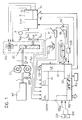
- an internal combustion engine for example a diesel engine for a motor vehicle, for example, a lift truck, is indicated MT.
- a hydraulic torque converter of known type includes a pump connected to the shaft 1 of the motor MT and a turbine with a shaft 2 which represents the output shaft of the converter.
- the shaft also represents the input of a power-shift gearbox, generally indicated PS.
- the gearbox is of known type and includes a plurality of hydraulic clutches DI and gear trains GT associated with the various gear ratios which can be achieved.
- the clutches can be activated selectively by the manual operation of a selector, indicated S.
- the hydraulic clutches DI of the gearbox (which may be constituted by friction devices with packs of hydraulically-operated discs of frictional material) are controlled by means of a corresponding number of enabling on/off solenoid valves V1, V2, ....V n and an associated electrically-operated pressure modulator EVP constituted, for example, by a proportional solenoid valve.
- the pressure modulator is connected to a source P of pressurised fluid constituted, for example, by a pump driven by the engine MT.
- the selective operation of one or more of the enabling solenoid valves V1 ??V n causes pressurised fluid to be supplied selectively to one or more clutches DI of the gearbox PS at a pressure defined by the modulator EVP which, in fact, selectively puts one of the gears or ratios of the gearbox into operation.
- the output shaft 3 of the gearbox PS is connected to the wheels of the motor vehicle in known manner, for example, by a crown wheel and pinion.
- Rotation-speed sensors associated with the output shaft 1 of the engine MT, the output shaft 2 of the hydraulic converter CI, and the output shaft 3 of the gearbox PS are indicated GM, GT, GU1 and GU2, respectively.
- These speed sensors may be constituted, for example, by Hall-effect sensors.
- the sensors GU1 and GU2 actually detect the angular velocity of the same output shaft of the gearbox PS, but an examination of the signals supplied thereby in combination, and in particular of their phase difference, enables the sense of rotation of the shaft to be determined.
- a electrical temperature sensor for detecting the temperature of the operating fluid in the hydraulic system for operating the gearbox is indicated TO.
- a first position sensor, indicated PA, is associated with the accelerator (pedal) A of the engine MT. This is an on-off sensor and is therefore not intended to indicate the extent of the operation of the accelerator but serves solely for discriminating between the activated and deactivated conditions thereof.
- a second position sensor is associated with the accelerator (pedal) A of the engine MT. This on-off sensor serves to detect the condition of maximum acceleration.
- a electrical position sensor for example a potentiometric sensor, indicated PI, is associated with a manual or pedal-operated control I which, as will become clearer from the following, substantially emulates the function of the friction clutch pedal of lift trucks with conventional hydrokinetic transmissions (the inching pedal).
- a further electrical position sensor is associated with the switch for starting the engine MT and is intended to supply a signal when the key which operates the switch is moved to the unstable engine-starting position.
- An electronic control unit indicated MCU, formed with the use of a microprocessor, has a series of counting inputs CNTR connected to the speed sensors GM, GT, GU1 and GU2, a plurality of analog inputs AI connected to the temperature sensor TO and the sensor PI, a plurality of digital inputs ID connected to the accelerator sensors PA and PA′, and a series MS of switches which are associated with the selector S and each of which is operated when the user selects a corresponding gear of the gearbox PS.
- the unit MCU has a series of digital outputs DO which control the enabling solenoid valves V1...Vn.
- a further digital output of the unit MCU controls the pressure modulator EVP by means of a digital/analog converter D/A.
- a further digital output of the control unit is connected to a relay RL which controls the electrical supply to the starter circuit of the engine MT.
- the unit MCU can enable or prevent the starting of the engine by means of this relay under the circumstances which will be described further below.
- Optical indicators such as a plurality of light-emitting diodes, generally indicated L in Figure 1, are also associated with the unit MCU.
- the unit ECU may conveniently also have a serial interface RS, for example an RS232 interface, for enabling it to converse with an external unit.
- a serial interface RS for example an RS232 interface
- the unit MCU is arranged by known techniques to acquire the signals supplied by the sensors connected thereto and to recognise a certain predefined number of operative conditions or phases of the engine MT and of the associated hydrodynamic transmission.
- Each of these phases is recognised upon the basis of the detection of the simultaneous occurrence of conditions which are indicated by the sensors and unambiguously define the phase, and according to logic criteria involving exclusion by priority and consequentiality in relation to the preceding phase.
- the unit MCU recognises a phase it brings a particular predefined control procedure into operation.
- one or more switches SW are also connected to the unit MCU for enabling the manual preselection of two basic operating modes of the control system, that is, the modes which will be referred to below as automatic mode and manual mode, respectively.
- the unit MCU controls the transmission on the basis of the states of the signals it receives from the various control devices and from the sensors , in order to recognise the operative phases and perform the functions described briefly above.
- the unit MCU controls the transmission solely on the basis of the signals supplied by the control devices, so that the vehicle and, in particular, the lift truck operates just like a conventional vehicle, that is, even in the event of a malfunction or damage to the control sensors and/or when some of the parameters monitored exceed predetermined limits.
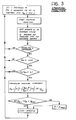
- This function results in the reaching and maintenance of a speed of movement of the vehicle (V T ) which - for each gear - is variable according to a predetermined function of the degree of operation of the manual or pedal-operated control I, that is, regardless of the prevailing running conditions of the vehicle.
- This function is put into effect when the sensors PI and MS indicate that the selector is set at a gear ratio and the control I is operated.
- Predetermined speeds of movement (V T ) of the vehicle corresponding to the gears and to the degrees of activation of the control I, indicated by the sensor PI, are stored in the memories of the control unit MCU in table form.
- the unit MCU checks (on the basis of the signals supplied by the sensor GU1 or GU2) whether the speed of rotation of the output shaft 3 of the gearbox PS corresponds to the speed of movement V T of the vehicle, which corresponds to the gear engaged and to the extent of operation of the control I. If so, the unit MCU does not alter the conditions for piloting the pressure modulator EVP and the enabling of the solenoid valves V1...Vn.
- the unit MCU pilots the proportional solenoid valve EVP so as to vary the pressure of the fluid supplied to the clutch or clutches engaged at that time, that is, until the speed of rotation of the shaft 3 corresponds to the vehicle speed value in its memory.
- the unit MCU pilots the pressure modulator EVP so as successively to increase the pressure of the fluid. Conveniently, in order to prevent instability, there should be a suitable delay between successive pressure increases.
- the pressure correction is incremental.
- the pressure is not actually detected directly by the unit MCU by means of a suitable pressure sensor but is derived on the basis of the average intensity of the current supplied to the proportional solenoid valve EVP and on the basis of the current/pressure characteristics of the solenoid valve.
- the unit ECU is conveniently arranged to calculate the individual pressure increments according to the following formula: in which p k is the pressure value to be achieved, p k ⁇ 1 is the pressure previously achieved, ⁇ is a positive constant, A is a predetermined function of V GU /V T ; in practice, A may assume, for example, a first value when V GU ⁇ 0.8V T and a second, lower value when V GU 0.8V T , V T is the speed of movement of the vehicle, read from the memory, V GU is the detected speed of rotation of the output shaft 3 of the gearbox, V GT is the speed of rotation of the input shaft 2 of the gearbox PS, and V GM is the speed of rotation of the shaft 1 of the engine MT.
- the unit MCU pilots the pressure modulator EVP so as to cause successive decreases in the pressure of the fluid.
- the viscosity, and hence the hydraulic response of the system varies with changes in the temperature of the fluid (detected by the sensor TO) and the unit MCU conveniently takes account of this by modifying the ⁇ *p calculated by equations (1) or (2) by multiplying it by a factor TF which is calculated as a function of the ratio between the viscosity of the fluid at its temperature T at the time in question and its viscosity at the reference temperature T rif .
- the viscosity/temperature characteristics of a hydraulic fluid are generally known or, at any rate, can be found.
- the law according to which the limit pressure (at the output of EVP) at which torque is not yet transmitted in the clutches DI (when the discs of the friction clutch start to slip) varies in dependence on the speed of rotation was found beforehand for the system under test.
- the law varies from one device to another but is generally substantially quadratic (parabolic) and can easily be stored in the unit MCU, for example, in table form.
- the unit MCU For each moment at which the unit MCU has to calculate an incremental pressure change for the operating fluid, therefore, it first calculates the theoretical pressure change according to equation (1) or equation (2) and then applies equation (3) to take account of the temperature of the fluid. It then subtracts from the calculated value of ⁇ ⁇ p a term p cf which takes account of the contribution to the pressure which is due to the variation in the centrifugal force and is derived from the aforementioned table.
- the unit MCU determines the current to be sent to the solenoid valve EVP on the basis of its pressure/current characteristic, which is also stored, and then pilots the solenoid valve correspondingly.
- EVP can be piloted, for example, by a pulse-width modulated signal (PWM).
- PWM pulse-width modulated signal
- the foregoing explanation relating to the inching function applies when the vehicle is stationary or moving in the logical direction of advance, that is, the direction which is desires by the user and is consistent with the gear engaged when the function is first put into effect.
- the control unit MCU is therefore conveniently arranged to check this condition by observing the phase difference between the signals of the speed sensors GU1 and GU2.
- the unit MCU of the system calculates and puts into effect an incremental pressure variation according to the following functional relationship: in which C is a constant and the other symbols have the meanings defined above.
- the unit continues to control the pressure of the fluid according to the equation (5) given above until the sensors GU1 and GU2 indicate that the vehicle has stopped or has started to move in the direction consistent with the gear engaged.
- the unit MCU adopts the equation (4) given above for calculating the incremental pressure variation (which may still be necessary).
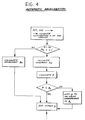
- the unit MCU controls the transmission so as to stop the vehicle automatically, even on a slope, without the need for the continuous operation of the brakes.
- This function is brought into operation each time the unit MCU detects an absence of signals for causing the vehicle to move.
- the unit MCU recognises the need to activate this function when:
- the unit MCU operates the pressure modulator EVP so as immediately to reduce the pressure of the hydraulic fluid to a predetermined minimum value and then simultaneously oPerates the solenoid valves V i corresponding to the clutches DI associated with the first forward gear and the first reverse gear.
- the unit MCU then checks the condition of the accelerator pedal (or pedals) again:
- the unit MCU can stop the vehicle even on a slope (upward or downward) and even without the continuous operation of the brakes (provided, of course, that the engine of the vehicle which drives the pump P is running).
- the unit MCU When the unit MCU detects that these conditions have occurred during an inching phase, it activates the stopping function in the manner described above.
- the unit MCU derives data concerning the deceleration of the vehicle from the sensor GU1 or GU2.
- the unit MCU puts into effect a procedure in which the fluid pressure is increased progressively by increments ⁇ p which are calculated in different ways for the retarding and reversal functions, respectively.
- the equations for the pressure increments ⁇ p for these functions will be given below.
- the unit MCU causes successive decreases ⁇ p in the pressure of the fluid and these are also calculated by different equations according to whether the deceleration control takes place during the operation of the reversal function or of the retarding function.
- the quantity beta defined by the equation (7) given above corresponds substantially to the energy dissipated in the clutches DI activated.
- the unit MCU compares ⁇ with a reference value ⁇ o which corresponds to the maximum energy which can be dissipated without damaging the clutches.
- Each individual pressure increment is thus effected upon the condition that ⁇ does not exceed ⁇ o .
- the unit MCU pilots the pressure modulator EVP so as to limit the fluid pressure p to the value which corresponds to ⁇ o .
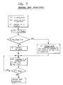
- the retarding function is activated, however, upon the condition that it has been detected beforehand that the speed of rotation of the output shaft 3 of the gearbox PS multiplied by its transmission ratio ⁇ and divided by the speed of rotation V GM of the engine shaft 1 is greater than a predetermined value Z which is greater than or equal to 1.
- the unit MCU reduces the pressure p of the operating fluid to a predetermined minimum value P min by means of the pressure modulator EVP, and then engages, by means of one or more valves V i , the first gear contrary to that which the sensor MSS indicates is selected at the time in question.
- the unit MCU checks (on the basis of the signal supplied by the sensor MS) whether the gear selected by the driver has changed in the meantime. If so, the unit MCU stops carrying out the retarding function, if not, the retarding procedure is continued, as indicated in the simplified flow chart of Figure 5. As can be seen from this chart, if at the first check V GU ⁇ ⁇ /V GM is not greater than Z, the unit MCU re-establishes the initial fluid-pressure value by means of EVP and the valves V i and disengages the opposing first gear previously engaged.
- the initial reduction in the fluid pressure and the engagement of the contrary first gear are carried out only after the condition ⁇ ⁇ V GU /V GM ⁇ Z has been detected for the first time whilst the retarding function is being carried out.
- the unit MCU recognises the situation in which this function should be activated when, apart from other considerations pertaining to the order of priority for the activation of the various functions, the signals supplied by the sensors PA and MS indicate that the accelerator A is depressed, the selector is not in the neutral position and the gear engaged by the selector relates to a direction of movement opposite that being achieved at that time by the on-off valves V i .
- the unit MCU pilots the pressure modulator EVP and the solenoid valves V i so as first to reduce the fluid pressure p to a minimum value p min and then to engage the first gear with the same sign (relating to the same direction) as the gear selected and indicated by the sensor MS.
- the unit MCU puts into effect the automatic deceleration procedure described above with reference to Figure 4.
- the unit MCU checks, on the basis of the signals supplied by the sensors GU1 or GU2 and MS whether the direction of advance of the vehicle corresponds to the gear engaged (for example, if the gear engaged is a forward gear, the vehicle should move forwards). If this check gives a positive result, the unit MCU then puts into effect the moving-off function which will be described below. If the result is negative, the unit MCU continues to carry out the preceding operations cyclically.
- This function is put into effect after a stopping phase when the unit MCU detects that, whilst the solenoid valves V i are keeping the gearbox PS in neutral, the sensors PA and MS indicate that the accelerator pedal A is depressed and the selector is not in the neutral position.
- the unit MCU pilots the pressure modulator EVP so as to bring the pressure p of the fluid to a minimum value p min .
- the solenoid valves V i the unit MCU engages the first gear or the gear which corresponds to the speed of the movement at the time in question (in the direction corresponding to the setting of the selector) according to whether the ratio ⁇ ⁇ V GU /V GM is less than or greater than a predetermined value W.
- the unit MCU pilots the pressure modulator EVP so as to cause a gradual pressure increase in a different manner according to the gear engaged, in dependence on V GU and ⁇ ⁇ V GU -V GT (this second quantity is indicative of the relative sliding between the packs of discs of the clutches DI).
- a test which has been used up to now to evaluate the performance of a lift truck consists of so-called moving off uphill or hill starting and measures the distance by which a lift truck with a predetermined load moves backwards when it changes rapidly and sequentially from the condition in which the brakes are operated to the condition in which the accelerator is depressed.
- the transmission system In order to limit the backward movement of the truck in such conditions, the transmission system must allow a high torque to be delivered very quickly. However, if the system is regulated so as to give a high torque quickly on an uphill slope, the same system will cause the truck to move off too abruptly when it is operating on the flat or on a downhill slope.
- a further sensor is associated with the accelerator pedal for supplying a signal (of the logic type) to the unit MCU when the pedal is fully depressed (kick-down).
- the unit MCU checks whether the speed of the output shaft 3 of the gearbox PS is below a certain predetermined value and, by comparing the signals of the sensors GU1 and GU2, checks whether the truck is moving backwards.
- the unit MCU pilots the modulator EVP so as to send a very high pressure to the clutches DI of the gearbox PS even up to the maximum pressure which the pump P can supply.
- the system thus rapidly delivers a very considerable torque, effectively limiting the rearward movement of the truck.
- the unit MCU is arranged to enable moving-off uphill with limited rearward movement even when the system is operating in the mode defined above as "manual".
- the unit MCU detects the time elapsing between each operation of the sensor PA and the operation of the sensor PA′ by the accelerator pedal A. If this time is less than a predetermined threshold value, the unit MCU operates the pressure modulator EVP so as to supply a high pressure quickly (even up to the maximum pressure which can be delivered by the pump).
- the unit MCU activates the normal starting procedure.
- the unit MCU reduces the fluid pressure by means of the pressure modulator EVP and then pilots the solenoid valves V i so as to change the gear.
Landscapes
- Engineering & Computer Science (AREA)
- General Engineering & Computer Science (AREA)
- Mechanical Engineering (AREA)
- Physics & Mathematics (AREA)
- Fluid Mechanics (AREA)
- Control Of Transmission Device (AREA)
Applications Claiming Priority (2)
| Application Number | Priority Date | Filing Date | Title |
|---|---|---|---|
| IT67695A IT1240557B (it) | 1990-09-14 | 1990-09-14 | Sistema elettronico di controllo per una trasmissione idrocinetica di tipo power-shift per un autoveicolo. |
| IT6769590 | 1990-09-14 |
Publications (2)
| Publication Number | Publication Date |
|---|---|
| EP0475918A2 true EP0475918A2 (de) | 1992-03-18 |
| EP0475918A3 EP0475918A3 (en) | 1993-10-20 |
Family
ID=11304571
Family Applications (1)
| Application Number | Title | Priority Date | Filing Date |
|---|---|---|---|
| EP19910830371 Withdrawn EP0475918A3 (en) | 1990-09-14 | 1991-09-10 | An electronic control system for a hydrokinetic power-shift transmission for a motor vehicle |
Country Status (2)
| Country | Link |
|---|---|
| EP (1) | EP0475918A3 (de) |
| IT (1) | IT1240557B (de) |
Cited By (4)
| Publication number | Priority date | Publication date | Assignee | Title |
|---|---|---|---|---|
| EP0617215A1 (de) * | 1993-03-25 | 1994-09-28 | Caterpillar Inc. | Elektrohydraulische Steuereinrichtung für einen Antriebsstrang eines Kraftfahrzeuges |
| US5509520A (en) * | 1994-06-15 | 1996-04-23 | Caterpillar Inc. | Electrohydraulic control device for a drive train of a machine |
| DE10201838A1 (de) * | 2002-01-18 | 2003-07-31 | Zahnradfabrik Friedrichshafen | Steuerung |
| EP1655517A1 (de) * | 2004-11-09 | 2006-05-10 | SAME DEUTZ-FAHR GROUP S.p.A. | System und Verfahren für Rückwärtsfahren eines Fahrzeugs, besonders für landwirtschaftliche Arbeitsfahrzeuge |
Citations (4)
| Publication number | Priority date | Publication date | Assignee | Title |
|---|---|---|---|---|
| JPS5757946A (en) * | 1981-08-14 | 1982-04-07 | Kamizaki Kokyu Koki Seisakusho Kk | Traveling speed control unit to farm tractor |
| GB2099936A (en) * | 1981-06-08 | 1982-12-15 | Ford Motor Co | Clutch pressure modifier valve in control of automatic transmission |
| EP0141005A1 (de) * | 1983-10-24 | 1985-05-15 | CARLO GRAZIANO S.p.A. TORINO | Getriebe mit hydraulisch gesteuerten Mehrfach-Scheiben-Kupplungen |
| JPS63242742A (ja) * | 1987-03-31 | 1988-10-07 | Hino Motors Ltd | 自動クラツチ装置 |
-
1990
- 1990-09-14 IT IT67695A patent/IT1240557B/it active IP Right Grant
-
1991
- 1991-09-10 EP EP19910830371 patent/EP0475918A3/en not_active Withdrawn
Patent Citations (4)
| Publication number | Priority date | Publication date | Assignee | Title |
|---|---|---|---|---|
| GB2099936A (en) * | 1981-06-08 | 1982-12-15 | Ford Motor Co | Clutch pressure modifier valve in control of automatic transmission |
| JPS5757946A (en) * | 1981-08-14 | 1982-04-07 | Kamizaki Kokyu Koki Seisakusho Kk | Traveling speed control unit to farm tractor |
| EP0141005A1 (de) * | 1983-10-24 | 1985-05-15 | CARLO GRAZIANO S.p.A. TORINO | Getriebe mit hydraulisch gesteuerten Mehrfach-Scheiben-Kupplungen |
| JPS63242742A (ja) * | 1987-03-31 | 1988-10-07 | Hino Motors Ltd | 自動クラツチ装置 |
Non-Patent Citations (2)
| Title |
|---|
| PATENT ABSTRACTS OF JAPAN vol. 013, no. 033 (M-789)25 January 1989 & JP-A-63 242 742 ( HINO MOTORS LTD ) 7 October 1988 * |
| PATENT ABSTRACTS OF JAPAN vol. 06, no. 134 (M-144)21 July 1982 & JP-A-57 057 946 ( KAMIZAKI KOKYU KOKI SEISAKUSHO KK ) * |
Cited By (7)
| Publication number | Priority date | Publication date | Assignee | Title |
|---|---|---|---|---|
| EP0617215A1 (de) * | 1993-03-25 | 1994-09-28 | Caterpillar Inc. | Elektrohydraulische Steuereinrichtung für einen Antriebsstrang eines Kraftfahrzeuges |
| US5456333A (en) * | 1993-03-25 | 1995-10-10 | Caterpillar Inc. | Electrohydraulic control device for a drive train of a vehicle |
| US5509520A (en) * | 1994-06-15 | 1996-04-23 | Caterpillar Inc. | Electrohydraulic control device for a drive train of a machine |
| DE10201838A1 (de) * | 2002-01-18 | 2003-07-31 | Zahnradfabrik Friedrichshafen | Steuerung |
| US7073645B2 (en) | 2002-01-18 | 2006-07-11 | Zf Friedrichshafen Ag | Control of a drivetrain |
| EP1655517A1 (de) * | 2004-11-09 | 2006-05-10 | SAME DEUTZ-FAHR GROUP S.p.A. | System und Verfahren für Rückwärtsfahren eines Fahrzeugs, besonders für landwirtschaftliche Arbeitsfahrzeuge |
| US7445101B2 (en) | 2004-11-09 | 2008-11-04 | Same Deutz-Fahr Group Spa | System and method for reversing the movement of a vehicle, in particular for an agricultural tractor |
Also Published As
| Publication number | Publication date |
|---|---|
| IT9067695A1 (it) | 1992-03-14 |
| IT9067695A0 (it) | 1990-09-14 |
| EP0475918A3 (en) | 1993-10-20 |
| IT1240557B (it) | 1993-12-17 |
Similar Documents
| Publication | Publication Date | Title |
|---|---|---|
| US5378211A (en) | Clutch mode control logic | |
| CA2109890C (en) | Engine control method for use with automatic clutch control | |
| US4714144A (en) | Method for controlling AMT system start from stop operation | |
| JP2563032B2 (ja) | 電気・機械式自動変速装置 | |
| CA2215002C (en) | Control apparatus for clutch of vehicle | |
| EP1395457B1 (de) | Verfahren zur umsteuerung der antriebsrichtung | |
| JP2004076934A (ja) | 高速自動車の電子制御式伝動装置 | |
| KR100304242B1 (ko) | 차량출발시의엔진연료제어장치및방법 | |
| JP2873348B2 (ja) | 自動クラッチ式変速機の制御装置 | |
| KR100264562B1 (ko) | 3→1속 스킵 변속시 변속감 향상 제어 장치 | |
| US6227999B1 (en) | Method and apparatus for operating a clutch in an automated mechanical transmission | |
| US6223874B1 (en) | Apparatus for operating a clutch in an automated mechanical transmission | |
| EP0475918A2 (de) | Elektronisches Steuerungssystem für hydrokinetisches Lastschaltgetriebe eines Kraftfahrzeuges | |
| JPH0587236A (ja) | 車両のクリープ制御装置 | |
| US6213916B1 (en) | Apparatus for operating a clutch in an automated mechanical transmission | |
| JPH08312741A (ja) | 無段自動変速機の制御装置 | |
| KR100290356B1 (ko) | 자동변속기차량의브레이킹시변속제어방법 | |
| JPH0739257B2 (ja) | 自走車両の駆動力制御装置 | |
| JPH07208601A (ja) | 自動変速制御装置 | |
| KR19980017060A (ko) | 자동 변속기의 드로틀 개도율 제어방법 |
Legal Events
| Date | Code | Title | Description |
|---|---|---|---|
| PUAI | Public reference made under article 153(3) epc to a published international application that has entered the european phase |
Free format text: ORIGINAL CODE: 0009012 |
|
| AK | Designated contracting states |
Kind code of ref document: A2 Designated state(s): BE DE FR GB |
|
| PUAL | Search report despatched |
Free format text: ORIGINAL CODE: 0009013 |
|
| AK | Designated contracting states |
Kind code of ref document: A3 Designated state(s): BE DE FR GB |
|
| STAA | Information on the status of an ep patent application or granted ep patent |
Free format text: STATUS: THE APPLICATION IS DEEMED TO BE WITHDRAWN |
|
| 18D | Application deemed to be withdrawn |
Effective date: 19940421 |