EP0475803B1 - Appareil destiné à permettre d'évaluer la brillance d'une surface, en particulier de la peau - Google Patents
Appareil destiné à permettre d'évaluer la brillance d'une surface, en particulier de la peau Download PDFInfo
- Publication number
- EP0475803B1 EP0475803B1 EP91402228A EP91402228A EP0475803B1 EP 0475803 B1 EP0475803 B1 EP 0475803B1 EP 91402228 A EP91402228 A EP 91402228A EP 91402228 A EP91402228 A EP 91402228A EP 0475803 B1 EP0475803 B1 EP 0475803B1
- Authority
- EP
- European Patent Office
- Prior art keywords
- reflection
- incidence
- directions
- skin
- normal
- Prior art date
- Legal status (The legal status is an assumption and is not a legal conclusion. Google has not performed a legal analysis and makes no representation as to the accuracy of the status listed.)
- Expired - Lifetime
Links
Images
Classifications
-
- A—HUMAN NECESSITIES
- A61—MEDICAL OR VETERINARY SCIENCE; HYGIENE
- A61B—DIAGNOSIS; SURGERY; IDENTIFICATION
- A61B5/00—Measuring for diagnostic purposes; Identification of persons
- A61B5/44—Detecting, measuring or recording for evaluating the integumentary system, e.g. skin, hair or nails
- A61B5/441—Skin evaluation, e.g. for skin disorder diagnosis
-
- A—HUMAN NECESSITIES
- A61—MEDICAL OR VETERINARY SCIENCE; HYGIENE
- A61B—DIAGNOSIS; SURGERY; IDENTIFICATION
- A61B5/00—Measuring for diagnostic purposes; Identification of persons
- A61B5/0059—Measuring for diagnostic purposes; Identification of persons using light, e.g. diagnosis by transillumination, diascopy, fluorescence
-
- G—PHYSICS
- G01—MEASURING; TESTING
- G01N—INVESTIGATING OR ANALYSING MATERIALS BY DETERMINING THEIR CHEMICAL OR PHYSICAL PROPERTIES
- G01N21/00—Investigating or analysing materials by the use of optical means, i.e. using sub-millimetre waves, infrared, visible or ultraviolet light
- G01N21/17—Systems in which incident light is modified in accordance with the properties of the material investigated
- G01N21/55—Specular reflectivity
- G01N21/57—Measuring gloss
-
- G—PHYSICS
- G01—MEASURING; TESTING
- G01N—INVESTIGATING OR ANALYSING MATERIALS BY DETERMINING THEIR CHEMICAL OR PHYSICAL PROPERTIES
- G01N21/00—Investigating or analysing materials by the use of optical means, i.e. using sub-millimetre waves, infrared, visible or ultraviolet light
- G01N21/17—Systems in which incident light is modified in accordance with the properties of the material investigated
- G01N21/21—Polarisation-affecting properties
Definitions
- the invention relates to an apparatus for examining a surface, comprising a light source capable of sending an incident beam on the surface to be examined, means comprising a polarizer and at least one analyzer making it possible to assess the reflection either with a parallel orientation of the directions of the polarizer and of the analyzer, or with a right-angle orientation of the above directions, the polarizer being arranged between the light source and the surface, while the analyzer is arranged on the path of the reflected beam, photodetector means sensitive to the light reflected by the surface being further provided, the light source being directive and the incident polarized beam falling on the surface to be studied at an angle of incidence between 0 ° and 90 ° limits excluded, the direction of polarization of the incident beam being perpendicular to the plane of incidence, the apparatus being arranged to measure the reflexio n following at least two different reflection directions, one of these reflection directions being substantially symmetrical with the incident direction relative to the normal to the surface.
- the invention relates more particularly, but not exclusively, to such an apparatus for evaluating the shine of the skin.
- FIG. 4 An apparatus of this type is shown by EP-A-0 335 163 and, more particularly, by FIG. 4 of this document, summarizing the prior art.
- the device in question is intended to detect the presence of foreign matter on the surfaces of a substrate.
- two reflected beams R1 and R2 in two different directions of reflection, are taken into account.
- Each beam reflected is analyzed according to a polarization angle, using an associated analyzer, without there being separation of this beam into two parts.
- This solution of FIG. 4 only allows a non-uniform directional distribution of the reflected light R and an unpredictable variation in the intensity of the beams R1 and R2.
- This device comprises a light source capable of sending an incident beam on the surface to be examined, this beam being reflected in two different directions; photodetector means sensitive to the reflected light make it possible to assess the specular reflection along one of the directions, and of the diffuse reflection along the other of the directions of reflection.
- the evaluation of the brightness is carried out by difference between the intensities of the specular and diffuse reflections (see in particular page 10 lines 33 to 35). Only one "global" shine is appreciated by this device. There is no question of gloss of different types, namely specular gloss and diffuse gloss.
- the main object of the invention is to provide an apparatus for evaluating the shine of a surface, in particular of the skin, which is more sensitive and more discriminating and which makes it possible to differentiate certain types of shine by its directivity properties. It is moreover desirable that the apparatus makes it possible to carry out the measurement over a reduced, almost point-like area, and free from color.
- an apparatus of the type defined above is characterized in that it comprises, to make it possible to evaluate the shine of the surface, in particular of the skin, means making it possible to perform, for each direction of reflection, the difference between reflection with parallel directions of polarization and analysis and reflection with perpendicular directions of polarization and analysis, the differences thus obtained constituting an appreciation of the so-called specular gloss and of the so-called diffuse gloss.
- the angle of incidence of the polarized beam on the surface is approximately 45 ° relative to the normal.
- the second direction of reflection considered is advantageously located in a range of plus or minus 10 ° on either side of the direction normal to the surface to be studied.
- This second direction is preferably substantially normal to said surface; it is generally located in the incidence plane.
- the analyzer means comprise, for each direction of reflection studied, a system making it possible to angularly separate the polarized light signals parallel and perpendicular to the plane of incidence; advantageously, two photodetectors are associated with each separator system to allow simultaneous measurement of these light signals.
- Each separator system is advantageously constituted by a polarization separator cube.
- Such an apparatus can be used to study biological phenomena which influence the shine of the skin, for example the kinetics of the sebaceous secretion, or to study the consequences on the shine of the skin of the application of cosmetic products, in particular the ability of a mattifying base to reduce the skin shine caused by sebum.
- the invention consists, apart from the arrangements set out above, of a certain number of other arrangements which will be more explicitly discussed below in connection with an exemplary embodiment described in detail with reference to the attached drawings. , but which is in no way limiting.
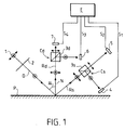
- FIG. 1 of these drawings is a diagram of an apparatus according to the invention.
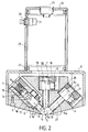
- Figure 2 finally, is a vertical section of the device according to the diagram of Figure 1.
- FIG. 1 one can see the diagram of an apparatus intended to make it possible to evaluate the gloss of a surface P, in particular of the skin.
- This device comprises a source 1 of non-polarized light.
- non-polarized light is symbolically represented by a circle with a point in the center, crossed by a double arrow along a diameter; light polarized perpendicular to the plane of incidence is represented by a circle with a point in the center, while light polarized parallel to the plane of incidence is represented only by a double arrow.
- the light source 1 is a white light source, directive and is equipped, for example, with an optical system (not shown) giving a parallel beam of direction D.
- a straight polarizer 2 is arranged with its mean plane orthogonal to the direction D, between the source 1 and the surface P so that the light falling in direction D on the skin P is polarized.
- the angle of incidence Ai, formed between the direction D of the incident beam and the normal direction N at the surface P is between 0 ° (normal incidence) and 90 ° (grazing incidence), these limits being excluded.
- the angle Ai is equal to 45 °, as shown in FIG. 1, or close to this value.
- the direction of polarization of the incident beam, after crossing the polarizer 2, is perpendicular to the plane of incidence.
- the device is designed to measure the reflection in two different directions of reflection Rs, Rd.
- the direction Rs which corresponds to the specular reflection, is symmetrical with the direction D with respect to the normal N.
- the light reflected in the direction Rd is obtained by diffuse reflection of the light which has penetrated inside the skin P , or by a surface reflection, if it has a certain irregularity.
- the second reflection direction Rd chosen to carry out the measurements is coincident with the direction N, or close to this direction, to within 10 °.
- This direction Rd is preferably located in the plane of incidence.
- the light reflected in the two directions Rs and Rd is no longer linearly polarized, unlike the incident light.
- Analyzer means Cs, Cd are provided for each direction of reflection studied and include a separator system, advantageously constituted by a polarization separator cube 3s, 3d, of the Wollaston prism type, which makes it possible to angularly separate, at right angles in the example considered, the light signals polarized in parallel and perpendicular to the plane of incidence, for each reflected beam Rs, Rd.
- a separator system advantageously constituted by a polarization separator cube 3s, 3d, of the Wollaston prism type, which makes it possible to angularly separate, at right angles in the example considered, the light signals polarized in parallel and perpendicular to the plane of incidence, for each reflected beam Rs, Rd.
- Two photodetectors respectively 4, 5 and 6, 7 are associated with each separating system to allow simultaneous measurement of the light signals. These photodetectors are connected to electronic means E making it possible to process the signals to provide the desired results.
- the photodetector 4 receives the fraction of the reflected beam Rs polarized perpendicular to the plane of incidence and provides a signal S1.
- the photodetector 5 receives the fraction of the beam Rs polarized parallel to the plane of incidence and provides a signal S2.
- the photodetector 6 receives the fraction of the beam Rd polarized perpendicular to the plane of incidence and supplies a signal S3.
- the photodetector 7 receives the fraction of the beam Rd polarized parallel to the plane of incidence and supplies a signal S4.
- the beam For each direction of reflection Rs, Rd, the beam comprises a component of intensity Ib, due essentially to the brightness of the surface, and a component of intensity Ic at the origin of the color of the surface considered, and coming from d '' a part of the light which penetrated in the medium where it underwent diffraction phenomena before being returned towards the photodetectors.
- S1 (Ib + 1/2 Ic) s
- S2 (1/2 Ic) s, for the beam Rs corresponding to the specular reflection.
- the results S1, S2, S3 and S4 can be displayed on a screen by the electronic means E and the differences can be made manually.
- the electronic means E are arranged to directly effect the difference between the signals S1 and S2, on the one hand, and the signals S3 and S4, on the other hand, and to display these differences, that is to say ie to display the specular brilliance Bs and the diffuse brilliance Bd.
- the ability of the device according to the invention to distinguish the two types of brightness Bs and Bd is quite interesting. Indeed, if the skin has a marked relief, the directivity of the gloss will be low and the value of the specular gloss Bs will only be significantly greater than the diffuse gloss Bd.
- the gloss will be much more directive and the value of the specular gloss Bs will be significantly higher than the value of the diffuse gloss Bd.
- FIG. 2 one can see an embodiment of an apparatus conforming to the diagram in FIG. 1.
- the apparatus comprises a base 8 in which is fixed, in a detachable manner, a core 9 where three housings 10, 11, 12 are provided, respectively admitting as axes the directions D, Rd and Rs.
- the axes of the housings compete at a point O which constitutes the center of an elliptical opening 13 provided at the lower part of the core and which is applied to the surface P to be examined.
- the housing 10 is extended, on the side opposite to the point O, by a chamber 14 of larger diameter in which is disposed a sleeve 15 coaxial with the direction D.
- the light source 1 comprising a bulb electric 16 provided, for example, with a lens to form a directional beam.
- the rectilinear polarizing filter 2 is disposed at the lower part of the sleeve 15, orthogonally to the axis of the sleeve.
- a photodetector element 17 is mounted in the wall of the sleeve 15, at the level of the emission zone of the bulb 16 to measure the average light intensity of this source. This element 17 is connected to electronic means, not shown, capable of modulating the result, of measurements of the photodetectors 4-7 as a function of the intensity of the light source.
- the housing 11 is extended, on the side opposite to the point O, by a chamber 18 in which is placed a block 19 where the polarization polarizing cube 3d and the associated photodetectors 6, 7 are housed.
- the housing 12 is extended, on the side opposite point O, by a cylindrical chamber 20 in which is placed a block 21 where the separator cube 3s and the photodetectors 4, 5 are respectively mounted.
- the base 8 has, in its upper central part, an opening surrounded by a flange 22 on which is fixed, in particular by screwing, a tubular element 23 closed, at its upper part, by a flat cover 24.
- a tubular element 23 closed, at its upper part, by a flat cover 24.
- an electrical connector 25 is provided for ensuring electrical connections with the outside, in particular for transmitting the results provided by the photodetector elements 4, 5, 6, 7 and 17 connected to this connector.
- a push button 26 is mounted in the wall of the element 23; this button 26 allows the light source 16 to be switched on for a determined time during which a measurement is made. The extinction is controlled manually by means of the push button 26, or automatically.
- the various electrical connections have not been shown inside the base 8 and the tubular element 23 which also constitutes a means for manual engagement and application of the measuring head formed by the assembly.
- the lower end of the core 9 is frustoconical, its small base being formed by the opening 13.
- the apparatus of the invention which makes it possible to quantify the phenomena of shine in space in two different directions, is particularly advantageous for the shine measurements carried out on the skin, which has surface irregularities.
- the light reflected by the surface of the skin can be diffused in various directions and not only in the specular direction, where it remains maximum.
- the apparatus of the invention takes account of this phenomenon.
- the shine of the skin is the result of the intrinsic shine of the skin and its surface condition.
Landscapes
- Health & Medical Sciences (AREA)
- Life Sciences & Earth Sciences (AREA)
- General Health & Medical Sciences (AREA)
- Physics & Mathematics (AREA)
- Pathology (AREA)
- Engineering & Computer Science (AREA)
- Animal Behavior & Ethology (AREA)
- Veterinary Medicine (AREA)
- Public Health (AREA)
- Surgery (AREA)
- Molecular Biology (AREA)
- Biophysics (AREA)
- Medical Informatics (AREA)
- Biomedical Technology (AREA)
- Heart & Thoracic Surgery (AREA)
- Chemical & Material Sciences (AREA)
- Dermatology (AREA)
- Analytical Chemistry (AREA)
- Biochemistry (AREA)
- Immunology (AREA)
- General Physics & Mathematics (AREA)
- Investigating Or Analysing Materials By Optical Means (AREA)
- Measurement Of The Respiration, Hearing Ability, Form, And Blood Characteristics Of Living Organisms (AREA)
- Measuring And Recording Apparatus For Diagnosis (AREA)
Description
- L'invention est relative à un appareil destiné à l'examen d'une surface, comprenant une source de lumière propre à envoyer un faisceau incident sur la surface à examiner, des moyens comprenant un polariseur et au moins un analyseur permettant d'apprécier la réflexion soit avec une orientation parallèle des directions du polariseur et de l'analyseur, soit avec une orientation à angle droit des susdites directions, le polariseur étant disposé entre la source de lumière et la surface, tandis que l'analyseur est disposé sur le trajet du faisceau réfléchi, des moyens photodétecteurs sensibles à la lumière renvoyée par la surface étant en outre prévus, la source de lumière étant directive et le faisceau incident polarisé tombant sur la surface à étudier selon un angle d'incidence compris entre 0° et 90° limites exclues, la direction de polarisation du faisceau incident étant perpendiculaire au plan d'incidence, l'appareil étant agencé pour mesurer la réflexion suivant au moins deux directions de réflexion différentes, l'une de ces directions de réflexion étant sensiblement symétrique de la direction incidente relativement à la normale à la surface.
- L'invention concerne plus particulièrement, mais non exclusivement, un tel appareil pour évaluer la brillance de la peau.
- Un appareil de ce type est montré par EP-A-0 335 163 et, plus particulièrement, par la figure 4 de ce document, résumant l'art antérieur. L'appareil en question est destiné à détecter la présence de matières étrangères sur les surfaces d'un substrat. Selon la réalisation de ladite figure 4, deux faisceaux réfléchis R1 et R2, suivant deux directions de réflexion différentes, sont pris en compte. Chaque faisceau réfléchi est analysé suivant un angle de polarisation, à l'aide d'un analyseur associé, sans qu'il y ait séparation de ce faisceau en deux parties. Cette solution de la figure 4 permet uniquement une distribution directionnelle non uniforme de la lumière réfléchie R et une variation de manière imprévisible de l'intensité des faisceaux R1 et R2. Pour remédier à ces inconvénients, il est proposé de travailler sur un seul faisceau Ro de lumière réfléchie diffuse, selon la réalisation des figures 1 et 2, et, sur cette seule direction de réflexion, on effectue la différence entre la réflexion avec des directions de polarisation et d'analyse parallèles (faisceau r1 de la figure 1) et la réflexion avec des directions de polarisation et d'analyse perpendiculaires (faisceau r2 de la figure 2). En conclusion, ce document EP-A-0 335 163 ne concerne pas une mesure de brillance mais et invite à travailler sur une seule direction de réflexion.
- On connaît par ailleurs, d'après EP-A-0 198 759 un appareil destiné à permettre l'évaluation de la brillance d'une surface, en particulier de la peau. Cet appareil comprend une source de lumière propre à envoyer un faisceau incident sur la surface à examiner, ce faisceau étant réfléchi dans deux directions différentes ; des moyens photodétecteurs sensibles à la lumière réfléchie permettent d'effectuer une appréciation de la réflexion spéculaire suivant l'une des directions, et de la réflexion diffuse suivant l'autre des directions de réflexion. L'évaluation de la brillance est effectuée par différence entre les intensités des réflexions spéculaire et diffuse (voir notamment page 10 lignes 33 à 35). Une seule brillance "globale" est appréciée par cet appareil. Il n'est pas question de brillance de types différents, à savoir brillance spéculaire et brillance diffuse.
- D'après FR-A-2 499 717, on connaît un procédé pour déterminer les défauts et les qualités d'une pièce de bois ; il n'est pas question de brillance spéculaire et de brillance diffuse.
- La société déposante a en outre proposé dans une demande de brevet antérieure FR-A-2 650 890 (89 10 709), déposée le 9 août 1989, un appareil pour évaluer la brillance de la peau. Les essais effectués ont montré qu'un tel appareil, tout en donnant des résultats satisfaisants, avait une sensibilité et un pouvoir discriminateur relativement réduits.
- L'invention a pour but, surtout, de fournir un appareil pour évaluer la brillance d'une surface, en particulier de la peau, qui soit plus sensible et plus discriminant et qui permette de différencier certains types de brillance par ses propriétés de directivité. Il est souhaitable, en outre, que l'appareil permette d'effectuer la mesure sur une zone réduite, presque ponctuelle, et en s'affranchissant de la couleur.
- Selon l'invention, un appareil du type défini précédemment, est caractérisé par le fait qu'il comporte, pour permettre d'évaluer la brillance de la surface, en particulier de la peau, des moyens permettant d'effectuer, pour chaque direction de réflexion, la différence entre la réflexion avec des directions de polarisation et d'analyse parallèles et la réflexion avec des directions de polarisation et d'analyse perpendiculaires, les différences ainsi obtenues constituant une appréciation de la brillance dite spéculaire et de la brillance dite diffuse.
- Avantageusement, l'angle d'incidence du faisceau polarisé sur la surface est d'environ 45° par rapport à la normale.
- La deuxième direction de réflexion considérée est avantageusement située dans une plage de plus ou moins 10° de part et d'autre de la direction normale à la surface à étudier. Cette deuxième direction est, de préférence, sensiblement normale à ladite surface ; elle est généralement située dans le plan d'incidence.
- Les moyens analyseurs comprennent, pour chaque direction de réflexion étudiée, un système permettant de séparer angulairement les signaux lumineux polarisés parallèlement et perpendiculairement au plan d'incidence ; avantageusement, deux photodétecteurs sont associés à chaque système séparateur pour permettre une mesure simultanée de ces signaux lumineux.
- Chaque système séparateur est avantageusement constitué par un cube séparateur de polarisation.
- Un tel appareil peut être utilisé pour étudier des phénomènes biologiques qui influent sur la brillance de la peau, par exemple la cinétique de la secrétion sébacée, ou pour étudier les conséquences sur la brillance de la peau de l'application de produits cosmétiques, notamment l'aptitude d'une base matifiante à diminuer la brillance cutanée provoquée par le sébum.
- L'invention consiste, mises à part les dispositions exposées ci-dessus, en un certain nombre d'autres dispositions dont il sera plus explicitement question ci-après à propos d'un exemple de réalisation décrit en détail avec référence aux dessins ci-annexés, mais qui n'est nullement limitatif.
- La figure 1, de ces dessins, est un schéma d'un appareil conforme à l'invention.
- La figure 2, enfin, est une coupe verticale de l'appareil conforme au schéma de la figure 1.
- En se reportant à la figure 1, on peut voir le schéma d'un appareil destiné à permettre d'évaluer la brillance d'une surface P, en particulier de la peau.
- Cet appareil comprend une source 1 de lumière non polarisée. Sur le schéma, la lumière non polarisée est représentée symboliquement par un cercle avec un point au centre, traversé par une double flèche suivant un diamètre ; une lumière polarisée perpendiculairement au plan d'incidence est représentée par un cercle avec un point au centre, tandis qu'une lumière polarisée parallèlement au plan d'incidence est représenté uniquement par une double flèche.
- La source de lumière 1 est une source de lumière blanche, directive et est équipée, par exemple, d'un système optique (non représenté) donnant un faisceau parallèle de direction D. Un polariseur 2 rectiligne est disposé avec son plan moyen orthogonal à la direction D, entre la source 1 et la surface P de sorte que la lumière tombant suivant la direction D sur la peau P est polarisée.
- L'angle d'incidence Ai, formé entre la direction D du faisceau incident et la direction normale N à la surface P est compris entre 0° (incidence normale) et 90° (incidence rasante), ces limites étant exclues. De préférence, l'angle Ai est égal à 45°, comme représenté sur la figure 1, ou voisin de cette valeur.
- La direction de polarisation du faisceau incident, après traversée du polariseur 2, est perpendiculaire au plan d'incidence.
- L'appareil est prévu pour mesurer la réflexion suivant deux directions de réflexion Rs, Rd différentes. La direction Rs, qui correspond à la réflexion spéculaire, est symétrique de la direction D par rapport à la normale N. La lumière réfléchie suivant la direction Rd est obtenue par réflexion diffuse de la lumière qui a pénétré à l'intérieur de la peau P, ou bien par une réflexion de surface, si celle-ci présente une certaine irrégularité.
- De préférence, la deuxième direction de réflexion Rd choisie pour effectuer les mesures est confondue avec la direction N, ou voisine de cette direction, à plus ou moins 10° près. Cette direction Rd est de préférence située dans le plan d'incidence.
- La lumière réfléchie suivant les deux directions Rs et Rd n'est plus polarisée linéairement, contrairement à la lumière incidente.
- Des moyens analyseurs Cs, Cd, sont prévus pour chaque direction de réflexion étudiée et comprennent un système séparateur, avantageusement constitué par un cube séparateur de polarisation 3s, 3d, du type prisme de Wollaston, qui permet de séparer angulairement, à angle droit dans l'exemple considéré, les signaux lumineux polarisés parallèlement et perpendiculairement au plan d'incidence, pour chaque faisceau réfléchi Rs, Rd.
- Deux photodétecteurs respectivement 4, 5 et 6, 7 sont associés à chaque système séparateur pour permettre une mesure simultanée des signaux lumineux. Ces photodétecteurs sont reliés à des moyens électroniques E permettant de traiter les signaux pour fournir les résultats cherchés.
- Le photodétecteur 4 reçoit la fraction du faisceau réfléchi Rs polarisée perpendiculairement au plan d'incidence et fournit un signal S1.
- Le photodétecteur 5 reçoit la fraction du faisceau Rs polarisée parallèlement au plan d'incidence et fournit un signal S2.
- Le photodétecteur 6 reçoit la fraction du faisceau Rd polarisée perpendiculairement au plan d'incidence et fournit un signal S3.
- Enfin, le photodétecteur 7 reçoit la fraction du faisceau Rd polarisée parallèlement au plan d'incidence et fournit un signal S4.
- Pour chaque direction de réflexion Rs, Rd, le faisceau comprend une composante d'intensité Ib, due essentiellement à la brillance de la surface, et une composante d'intensité Ic à l'origine de la couleur de la surface considérée, et provenant d'une partie de la lumière qui a pénétré dans le milieu où elle a subi des phénomènes de diffraction avant d'être renvoyée vers les photodétecteurs. En pratique on peut écrire que :
S1 = (Ib + 1/2 Ic)s,
S2 = (1/2 Ic)s, pour le faisceau Rs correspondant à la réflexion spéculaire. - Pour le faisceau Rd, correspondant à la réflexion diffuse, on peut écrire :
S3 = (Ib + 1/2 Ic)d
S4 = (1/2 Ic)d. - En faisant la différence entre les deux résultats S1 et S2, on obtient la valeur S1 - S2 = (Ib)s qui représente la mesure de la brillance dans la direction Rs, brillance que l'on peut appeler brillance spéculaire Bs.
- En faisant la différence entre les résultats S3 et S4, on obtient l'expression S3 - S4 = (Ib)d qui représente la brillance dans la direction Rd, et que l'on peut appeler brillance diffuse Bd.
- Les résultats S1, S2, S3 et S4 peuvent être affichés sur un écran par les moyens électroniques E et les différences peuvent être effectuées manuellement.
- Selon une autre possibilité, les moyens électroniques E sont agencés pour effectuer directement la différence entre les signaux S1 et S2, d'une part, et les signaux S3 et S4, d'autre part, et pour afficher ces différences, c'est-à-dire pour afficher la brillance spéculaire Bs et la brillance diffuse Bd.
- La capacité de l'appareil selon l'invention, à distinguer les deux types de brillance Bs et Bd est tout-à-fait intéressante. En effet, si la peau présente un relief marqué, la directivité de la brillance sera faible et la valeur de la brillance spéculaire Bs ne sera que sensiblement supérieure à la brillance diffuse Bd.
- Par contre, si la surface de la peau est très lisse, notamment après traitement par un produit cosmétique, la brillance sera beaucoup plus directive et la valeur de la brillance spéculaire Bs sera nettement supérieure à la valeur de la brillance diffuse Bd.
- En se reportant à la figure 2 on peut voir un exemple de réalisation d'un appareil conforme au schéma de la figure 1.
- L'appareil comprend une embase 8 dans laquelle est fixé, de manière démontable, un noyau 9 où sont prévus trois logements 10, 11, 12 admettant respectivement comme axes les directions D, Rd et Rs. Les axes des logements concourent en un point O qui constitue le centre d'une ouverture elliptique 13 prévue à la partie inférieure du noyau et qui est appliquée sur la surface P à examiner.
- Le logement 10 se prolonge, du côté opposé au point O, par une chambre 14 de plus fort diamètre dans laquelle est disposé un manchon 15 coaxial à la direction D. A l'intérieur du manchon est placée la source de lumière 1 comportant une ampoule électrique 16 munie, par exemple, d'une lentille pour former un faisceau directif. Le filtre polarisant rectiligne 2 est disposé à la partie inférieure du manchon 15, orthogonalement à l'axe du manchon. Un élément photodétecteur 17 est monté dans la paroi du manchon 15, au niveau de la zone d'émission de l'ampoule 16 pour mesurer l'intensité lumineuse moyenne de cette source. Cet élément 17 est relié à des moyens électroniques non représentés propres à moduler le résultat,des mesures des photodétecteurs 4-7 en fonction de l'intensité de la source lumineuse.
- Le logement 11 est prolongé, du côté opposé au point O, par une chambre 18 dans laquelle est placé un bloc 19 où sont logés le cube séparateur de polarisation 3d et les photodétecteurs associés 6, 7.
- De la même manière le logement 12 est prolongé, du côté opposé au point O, par une chambre cylindrique 20 dans laquelle est placé un bloc 21 où sont montés respectivement le cube séparateur 3s et les photodétecteurs 4, 5.
- Il est à noter qu'en adoptant pour l'angle Ai la valeur de 45° ; pour Rs la direction symétrique relativement à la normale ; et pour Rd, la direction de la normale, on peut loger l'ensemble de la source de lumière, des cubes séparateurs et des photodétecteurs dans un volume minimal.
- L'embase 8 comporte, dans sa partie centrale supérieure, une ouverture entourée par une collerette 22 sur laquelle est fixé, notamment par vissage, un élément tubulaire 23 fermé, à sa partie supérieure, par un couvercle plan 24. Au centre de ce couvercle est prévu un connecteur électrique 25 permettant d'assurer les liaisons électriques avec l'extérieur notamment pour transmettre les résultats fournis par les éléments photodétecteurs 4, 5, 6, 7 et 17 reliés à ce connecteur. Un bouton-poussoir 26 est monté dans la paroi de l'élément 23 ; ce bouton 26 permet de commander l'allumage de la source lumineuse 16 pendant un temps déterminé au cours duquel est effectué une mesure. L'extinction est commandée manuellement par l'intermédiaire du bouton-poussoir 26, ou automatiquement. Les diverses liaisons électriques n'ont pas été représentées à l'intérieur de l'embase 8 et de l'élément tubulaire 23 qui constitue également un moyen de prise manuelle et d'application de la tête de mesure formée par l'ensemble.
- On peut remarquer que l'extrémité inférieure du noyau 9 est tronconique, sa petite base étant constituée par l'ouverture 13. Pour assurer un bon appui de la tête de mesure sur la surface P on peut prévoir une couronne 27 dont le bord inférieur est situé sensiblement dans le plan de l'ouverture 13.
- L'utilisation de l'appareil de la figure 2 résulte immédiatement des explications qui précèdent.
- L'opérateur saisit l' appareil par la partie cylindrique de l'élément tubulaire 23 et applique le point O sur le centre de la zone où la mesure doit être effectuée. Puis, en appuyant sur le bouton-poussoir 26, l'opérateur déclenche la mesure en ce point.
- L'appareil de l'invention, qui permet de quantifier dans l'espace les phénomènes de brillance dans deux directions différentes est particulièrement intéressant pour les mesures de brillance effectuées sur la peau, qui présente des irrégularités de surface. La lumière réfléchie par la surface de la peau peut être diffusée dans diverses directions et non pas uniquement dans la direction spéculaire, où elle reste maximale. L'appareil de l'invention tient compte de ce phénomène.
- On peut dire que la brillance de la peau est la résultante de la brillance intrinsèque de la peau et de son état de surface.
- Il est à noter que grâce aux cubes séparateurs de polarisation 3s, 3d, aucun mouvement mécanique n'est à effectuer entre le polariseur et l'analyseur, ce qui améliore la précision de l'appareil et permet d'effectuer une mesure simultanée des signaux polarisés parallèlement et perpendiculairement au plan d'incidence.
Claims (9)
- Appareil destiné à l'examen d'une surface, comprenant une source de lumière (1) propre à envoyer un faisceau incident sur la surface (P) à examiner, des moyens comprenant un polariseur (2) et au moins un analyseur (Cs, Cd) permettant d'apprécier la réflexion soit avec une orientation parallèle des directions du polariseur et de l'analyseur, soit avec une orientation à angle droit des susdites directions, le polariseur (2) étant disposé entre la source de lumière (1) et la surface (P), tandis que l'analyseur (Cs, Cd) est disposé sur le trajet du faisceau réfléchi, des moyens photodétecteurs (4, 5, 6, 7) sensibles à la lumière renvoyée par la surface (P) étant en outre prévus, la source de lumière (1) étant directive et le faisceau incident polarisé tombant sur la surface à étudier selon un angle d'incidence (Ai) compris entre 0° et 90° limites exclues, la direction de polarisation du faisceau incident étant perpendiculaire au plan d'incidence, l'appareil étant agencé pour mesurer la réflexion suivant au moins deux directions de réflexion différentes (Rs, Rd), l'une (Rs) de ces directions de réflexion étant sensiblement symétrique de la direction incidente (D) relativement à la normale (N) à la surface, caractérisé par le fait qu'il comporte, pour permettre l'évaluation de la brillance de la surface, en particulier de la peau, des moyens (Cd, Cs ; 4, 5, 6, 7 ; E) permettant d'effectuer, pour chaque direction de réflexion, la différence [(S1-S2) ; (S3-S4)] entre la réflexion avec des directions de polarisation et d'analyse parallèles et la réflexion avec des directions de polarisation et d'analyse perpendiculaires, les différences [(S1-S2) ; (S3-S4)] ainsi obtenues constituant une appréciation de la brillance dite spéculaire et de la brillance dite diffuse.
- Appareil selon la revendication 1, caractérisé par le fait que l'angle d'incidence (Ai) du faisceau incident est d'environ 45° par rapport à la normale, l'angle de la première direction (Rs) de réflexion étant également voisin de 45°.
- Appareil selon la revendication 1 ou 2, caractérisé par le fait que la deuxième direction de réflexion (Rd) est située dans une plage de plus ou moins 10° de part et d'autre de la direction (N) normale à la surface à étudier.
- Appareil selon la revendication 3, caractérisé par le fait que la deuxième direction de réflexion (Rd) est sensiblement normale à ladite surface.
- Appareil selon l'une des revendications précédentes, caractérisé par le fait que les moyens analyseurs comprennent, pour chaque direction de réflexion étudiée (Rs, Rd), un système (Cs, Cd) permettant de séparer angulairement les signaux lumineux polarisés parallèlement et perpendiculairement au plan d'incidence.
- Appareil selon la revendication 5, caractérisé par le fait que deux photodétecteurs (4, 5 ; 6, 7) sont associés à chaque système séparateur (Cs, Cd), pour permettre une mesure simultanée des signaux lumineux.
- Appareil selon la revendication 5 ou 6, caractérisé par le fait que chaque système séparateur (Cs, Cd) est constitué par un cube séparateur de polarisation (3s, 3d).
- Application d'un appareil selon l'une quelconque des revendications précédentes à l'étude de la cinétique de la sécrétion sébacée.
- Application d'un appareil selon l'une quelconque des revendications 1 à 7 à l'étude de l'aptitude pour une base matifiante à diminuer la brillance de la peau due au sébum.
Applications Claiming Priority (2)
| Application Number | Priority Date | Filing Date | Title |
|---|---|---|---|
| FR9010379 | 1990-08-16 | ||
| FR9010379A FR2665959B1 (fr) | 1990-08-16 | 1990-08-16 | Appareil destine a permettre d'evaluer la brillance d'une surface, en particulier de la peau. |
Publications (2)
| Publication Number | Publication Date |
|---|---|
| EP0475803A1 EP0475803A1 (fr) | 1992-03-18 |
| EP0475803B1 true EP0475803B1 (fr) | 1995-05-03 |
Family
ID=9399690
Family Applications (1)
| Application Number | Title | Priority Date | Filing Date |
|---|---|---|---|
| EP91402228A Expired - Lifetime EP0475803B1 (fr) | 1990-08-16 | 1991-08-12 | Appareil destiné à permettre d'évaluer la brillance d'une surface, en particulier de la peau |
Country Status (6)
| Country | Link |
|---|---|
| US (1) | US5198875A (fr) |
| EP (1) | EP0475803B1 (fr) |
| JP (1) | JP3194152B2 (fr) |
| CA (1) | CA2049264C (fr) |
| DE (1) | DE69109413T2 (fr) |
| FR (1) | FR2665959B1 (fr) |
Families Citing this family (58)
| Publication number | Priority date | Publication date | Assignee | Title |
|---|---|---|---|---|
| JP3358099B2 (ja) * | 1994-03-25 | 2002-12-16 | オムロン株式会社 | 光学式センサ装置 |
| FR2719989B1 (fr) * | 1994-05-20 | 1996-07-05 | Oreal | Procédé pour la détermination de grandeurs caractéristiques du comportement d'une surface, notamment de la peau humaine, soumise à un rayonnnement lumineux, et appareil pour sa mise en Óoeuvre. |
| US5477321A (en) * | 1994-08-31 | 1995-12-19 | Bayer Corporation | Dual beam tunable spectrometer |
| AT403654B (de) * | 1994-12-01 | 1998-04-27 | Binder Michael Dr | Einrichtung zur optischen untersuchung von human-haut sowie derselben zugeordnete auswertungs-einrichtung |
| NL9500628A (nl) * | 1995-03-31 | 1996-11-01 | Grafisch Management Adviesbure | Drukwerkoppervlak-meetinrichting. |
| US5742392A (en) * | 1996-04-16 | 1998-04-21 | Seymour Light, Inc. | Polarized material inspection apparatus |
| AU715053B2 (en) * | 1996-06-13 | 2000-01-13 | Pola Chemical Industries Inc. | Method for evaluating make-up cosmetic product and powder composition |
| FR2784018B1 (fr) | 1998-10-06 | 2000-12-08 | Serobiologiques Lab Sa | Procede de mesure des proprietes de reflexion d'une surface et dispositif pour sa mise en oeuvre |
| US20050046830A1 (en) * | 1999-04-16 | 2005-03-03 | John Karp | Polarized material inspection apparatus and system |
| US6697156B1 (en) * | 2000-04-05 | 2004-02-24 | John Karp | Polarized material inspection apparatus |
| US20040111031A1 (en) * | 1999-07-22 | 2004-06-10 | Alfano Robert R. | Spectral polarizing tomographic dermatoscope |
| JP2003508772A (ja) | 1999-07-27 | 2003-03-04 | コロラド・スクール・オブ・マインズ | 平行検出分光楕円偏光計/偏光計 |
| US6993167B1 (en) * | 1999-11-12 | 2006-01-31 | Polartechnics Limited | System and method for examining, recording and analyzing dermatological conditions |
| FR2810737B1 (fr) * | 2000-06-23 | 2003-04-18 | Oreal | Appareil et procede d'examen d'une surface |
| US6721052B2 (en) * | 2000-12-20 | 2004-04-13 | Kla-Technologies Corporation | Systems for measuring periodic structures |
| FR2826857B1 (fr) * | 2001-07-09 | 2004-03-12 | Oreal | Instrument pour observer la peau ou les cheveux |
| FR2829344B1 (fr) * | 2001-08-29 | 2004-10-01 | Oreal | Dispositif d'acquisition d'au moins une image d'au moins une partie du visage ou de la chevelure d'une personne |
| US6922523B2 (en) * | 2001-11-08 | 2005-07-26 | Johnson & Johnson Consumer Companies, Inc. | Method of promoting skin care products |
| US7738032B2 (en) * | 2001-11-08 | 2010-06-15 | Johnson & Johnson Consumer Companies, Inc. | Apparatus for and method of taking and viewing images of the skin |
| US20040146290A1 (en) * | 2001-11-08 | 2004-07-29 | Nikiforos Kollias | Method of taking images of the skin using blue light and the use thereof |
| US6907193B2 (en) * | 2001-11-08 | 2005-06-14 | Johnson & Johnson Consumer Companies, Inc. | Method of taking polarized images of the skin and the use thereof |
| US6961517B2 (en) * | 2001-11-08 | 2005-11-01 | Johnson & Johnson Consumer Companies, Inc. | Method of promoting skin care products |
| US7024037B2 (en) * | 2002-03-22 | 2006-04-04 | Unilever Home & Personal Care Usa, A Division Of Conopco, Inc. | Cross-polarized imaging method for measuring skin ashing |
| KR101035667B1 (ko) | 2002-05-09 | 2011-05-19 | 소니 주식회사 | 생체 인식 패턴 검출 장치, 개인 인증 장치 및 방법 |
| KR100484812B1 (ko) * | 2002-09-03 | 2005-04-22 | 엘지전자 주식회사 | 이미지 센서를 이용한 표면 검사방법 및 검사장치 |
| US7006223B2 (en) * | 2003-03-07 | 2006-02-28 | 3Gen, Llc. | Dermoscopy epiluminescence device employing cross and parallel polarization |
| ATE375585T1 (de) * | 2003-03-14 | 2007-10-15 | Liwas Aps | Einrichtung zur detektion eines strassenoberflächenzustands |
| US7336810B2 (en) | 2003-06-11 | 2008-02-26 | KOSé CORPORATION | Skin evaluation method and image simulation method |
| DE10353001A1 (de) * | 2003-11-13 | 2005-06-16 | Conti Temic Microelectronic Gmbh | Vorrichtung und Verfahren zur Objekterkennung für eine Kraftfahrzeug-Sicherheitseinrichtung |
| SE0303048L (sv) * | 2003-11-17 | 2004-12-28 | Optonova Ab | Förfarande och anordning för beröringsfri avsyning och inmätning av ytegenskaper och ytdefekter på en materialyta |
| US7004599B2 (en) * | 2004-01-02 | 2006-02-28 | 3Gen, Llc. | Illuminated mirror employing cross and parallel polarization |
| US8026942B2 (en) | 2004-10-29 | 2011-09-27 | Johnson & Johnson Consumer Companies, Inc. | Skin imaging system with probe |
| DE102005050807B4 (de) * | 2005-10-24 | 2010-04-08 | Dan Hossu | Vorrichtung zur Messung von Erhöhungen und/oder Vertiefungen einer Oberfläche |
| JP2008046061A (ja) * | 2006-08-21 | 2008-02-28 | Pola Chem Ind Inc | 干渉光による肌の鑑別法 |
| DE102006042412B4 (de) * | 2006-09-06 | 2009-01-02 | Yara International Asa | Verfahren zum berührungslosen Bestimmen biophysikalischer Parameter von mit Tau benetzten Pflanzenbeständen |
| US20080083886A1 (en) * | 2006-09-14 | 2008-04-10 | 3M Innovative Properties Company | Optical system suitable for processing multiphoton curable photoreactive compositions |
| US7551359B2 (en) * | 2006-09-14 | 2009-06-23 | 3M Innovative Properties Company | Beam splitter apparatus and system |
| US7764303B2 (en) * | 2006-10-02 | 2010-07-27 | Johnson & Johnson Consumer Companies, Inc. | Imaging apparatus and methods for capturing and analyzing digital images of the skin |
| EP2223650A1 (fr) | 2009-02-25 | 2010-09-01 | The Provost, Fellows and Scholars of the College of the Holy and Undivided Trinity of Queen Elizabeth near Dublin | Procédé et appareil d'imagerie de tomographie de tissus |
| WO2011067162A1 (fr) * | 2009-12-02 | 2011-06-09 | Unilever Plc | Appareil et procede de mesure de l'âge de la peau |
| JP5691687B2 (ja) * | 2011-03-14 | 2015-04-01 | 株式会社リコー | 検査装置 |
| WO2012133431A1 (fr) * | 2011-03-31 | 2012-10-04 | オリンパスメディカルシステムズ株式会社 | Dispositif d'endoscope, capuchon d'endoscope et procédé d'analyse |
| US8588605B2 (en) | 2011-09-21 | 2013-11-19 | Globalmedia Group, Llc | Dual polarizing hood |
| JP6083119B2 (ja) * | 2012-03-08 | 2017-02-22 | 株式会社リコー | 光学センサ及び画像形成装置 |
| US9480529B2 (en) * | 2012-06-22 | 2016-11-01 | S & Y Enterprises Llc | Aesthetic treatment device and method |
| US9364684B2 (en) | 2012-06-22 | 2016-06-14 | S & Y Enterprises Llc | Aesthetic treatment device and method |
| JP2014174132A (ja) * | 2013-03-13 | 2014-09-22 | Ricoh Co Ltd | 光学センサ及び画像形成装置 |
| US9458990B2 (en) | 2013-08-01 | 2016-10-04 | 3Gen, Inc. | Dermoscopy illumination device with selective polarization and orange light for enhanced viewing of pigmented tissue |
| TW201944981A (zh) * | 2014-11-10 | 2019-12-01 | 日商資生堂股份有限公司 | 皮膚光澤之評價方法、皮膚光澤提升劑之探索方法及皮膚光澤提升劑 |
| US9775500B2 (en) | 2014-11-20 | 2017-10-03 | Globalmedia Group, Llc | Polarizing endoscopy system and method |
| JP6574074B2 (ja) | 2016-02-08 | 2019-09-11 | イクアリティ コスメティクス インコーポレイテッドEquality Cosmetics, Inc. | 視覚的にカスタマイズされた化粧品を配合および分配するための装置および方法 |
| EP3384829A1 (fr) * | 2017-04-05 | 2018-10-10 | Koninklijke Philips N.V. | Mesure de brillance de la peau pour une estimation quantitative de brillance de la peau |
| US10441379B2 (en) | 2017-12-28 | 2019-10-15 | 3Gen, Inc. | Multipurpose medical illuminator with magnification |
| CN208477552U (zh) * | 2018-04-01 | 2019-02-05 | 印芯科技股份有限公司 | 光学识别模块 |
| US10575623B2 (en) | 2018-06-29 | 2020-03-03 | Sephora USA, Inc. | Color capture system and device |
| DE102018222122B4 (de) * | 2018-12-18 | 2025-11-27 | Henkel Ag & Co. Kgaa | Verfahren zum bestimmen von glanz eines abschnitts einer haut eines benutzers |
| US11395714B2 (en) | 2019-11-11 | 2022-07-26 | Dermlite Llc | Medical illuminator with variable polarization |
| WO2022144806A1 (fr) * | 2020-12-30 | 2022-07-07 | Shiseido Company, Limited | Système et appareil d'évaluation du taux de sébum |
Family Cites Families (11)
| Publication number | Priority date | Publication date | Assignee | Title |
|---|---|---|---|---|
| BE532262A (fr) * | 1953-10-12 | |||
| US2947212A (en) * | 1956-04-30 | 1960-08-02 | American Brass Co | Method of detecting surface conditions of sheet metal |
| US3060793A (en) * | 1960-07-22 | 1962-10-30 | Arthur N Wells | Apparatus for determining ellipticity of surface reflected plane polarized light |
| FR2175259A5 (fr) * | 1972-03-06 | 1973-10-19 | Sklyarsky Yakov | |
| US3904293A (en) * | 1973-12-06 | 1975-09-09 | Sherman Gee | Optical method for surface texture measurement |
| US4398541A (en) * | 1978-05-25 | 1983-08-16 | Xienta, Inc. | Method and apparatus for measuring moisture content of skin |
| FI63835C (fi) * | 1981-02-10 | 1983-08-10 | Altim Control Ky | Foerfarande foer identifiering av ett virkes ytegenskaper |
| FR2579884B1 (fr) * | 1985-04-09 | 1988-12-02 | Sanofi Sa | |
| JPH0820371B2 (ja) * | 1988-01-21 | 1996-03-04 | 株式会社ニコン | 欠陥検査装置及び欠陥検査方法 |
| JPH0774788B2 (ja) * | 1988-03-28 | 1995-08-09 | 株式会社堀場製作所 | 異物有無検査装置 |
| FR2650890B1 (fr) * | 1989-08-09 | 1993-02-19 | Oreal | Appareil destine a permettre l'evaluation de la brillance d'une surface, en particulier de la peau |
-
1990
- 1990-08-16 FR FR9010379A patent/FR2665959B1/fr not_active Expired - Fee Related
-
1991
- 1991-08-09 US US07/742,754 patent/US5198875A/en not_active Expired - Lifetime
- 1991-08-12 DE DE69109413T patent/DE69109413T2/de not_active Expired - Fee Related
- 1991-08-12 EP EP91402228A patent/EP0475803B1/fr not_active Expired - Lifetime
- 1991-08-15 CA CA002049264A patent/CA2049264C/fr not_active Expired - Fee Related
- 1991-08-16 JP JP28905891A patent/JP3194152B2/ja not_active Expired - Fee Related
Also Published As
| Publication number | Publication date |
|---|---|
| DE69109413T2 (de) | 1996-02-08 |
| JPH05220130A (ja) | 1993-08-31 |
| US5198875A (en) | 1993-03-30 |
| EP0475803A1 (fr) | 1992-03-18 |
| FR2665959B1 (fr) | 1994-01-14 |
| CA2049264A1 (fr) | 1992-02-17 |
| FR2665959A1 (fr) | 1992-02-21 |
| DE69109413D1 (de) | 1995-06-08 |
| JP3194152B2 (ja) | 2001-07-30 |
| CA2049264C (fr) | 2000-07-04 |
Similar Documents
| Publication | Publication Date | Title |
|---|---|---|
| EP0475803A1 (fr) | Appareil destiné à permettre d'évaluer la brillance d'une surface, en particulier de la peau | |
| WO2002006779A2 (fr) | Ellipsometre spectroscopique compact | |
| EP2376882B1 (fr) | Dispositif et procede de determination d'une information de polarisation et imageur polarimetrique. | |
| FR2491615A1 (fr) | Procede de mesure optoelectronique et dispositifs pour la determination de la qualite de surfaces a reflexion diffuse | |
| JP3360822B2 (ja) | 同時多数角度/多数波長の楕円偏光器および方法 | |
| FR2499717A1 (fr) | Procede pour identifier les proprietes de surface des pieces de bois, en vue de leur classification | |
| EP2734884A1 (fr) | Dispositif optique d'éclairage conoscopique a cone creux pour microscope optique et procédé de microscopie optique en conoscopie | |
| US7999936B1 (en) | Combined transmittance and angle selective scattering measurement of fluid suspended particles for simultaneous determination of refractive index, extinction coefficient, particle size and particle density | |
| EP0974042A1 (fr) | Polarimetre et procede de mesure correspondant | |
| US6414311B1 (en) | Spectrometer accessory for carrying out attenuated total reflectance measurements | |
| FR3087539A1 (fr) | Instrument de mesure avec systeme de visualisation du spot de mesure et accessoire de visualisation pour un tel instrument de mesure | |
| EP3054281A1 (fr) | Dispositif de mesure d'un signal optique rétrodiffusé par un échantillon | |
| FR2650890A1 (fr) | Appareil destine a permettre l'evaluation de la brillance d'une surface, en particulier de la peau | |
| CN201788152U (zh) | 空间偏离拉曼光谱探头 | |
| KR102503469B1 (ko) | 휴대용 비파괴 농산물 내부품질 측정장치 | |
| FR2595471A1 (fr) | Dispositif d'ellipsometrie spectroscopique a fibres optiques | |
| AU622939B2 (en) | Measuring surface quality of a lens | |
| EP0516562B1 (fr) | Dispositif de mesure de courant par fibre optique | |
| WO2023222815A1 (fr) | Appareil et procédé de spectrométrie raman ou de fluorescence à analyse instantanée de polarisation | |
| FR3090111A1 (fr) | Support pour sonde à ultrasons. | |
| FR2805343A1 (fr) | Dispositif de controle de l'etat d'une surface | |
| EP4370907B1 (fr) | Procédé de contrôle des défauts de surface d'une pièce de fonderie en métal monocristallin et système de mise en oeuvre | |
| FR2615953A1 (fr) | Dispositif pour etalonner un appareil de mesure de l'indice de formation d'une feuille de papier | |
| JP3568631B2 (ja) | 宝石の色鑑定装置 | |
| FR2501861A1 (fr) | Ellipsometre comportant un prisme a reflexions totales |
Legal Events
| Date | Code | Title | Description |
|---|---|---|---|
| PUAI | Public reference made under article 153(3) epc to a published international application that has entered the european phase |
Free format text: ORIGINAL CODE: 0009012 |
|
| 17P | Request for examination filed |
Effective date: 19910814 |
|
| AK | Designated contracting states |
Kind code of ref document: A1 Designated state(s): BE DE FR GB IT NL |
|
| 17Q | First examination report despatched |
Effective date: 19940405 |
|
| GRAA | (expected) grant |
Free format text: ORIGINAL CODE: 0009210 |
|
| AK | Designated contracting states |
Kind code of ref document: B1 Designated state(s): BE DE FR GB IT NL |
|
| PG25 | Lapsed in a contracting state [announced via postgrant information from national office to epo] |
Ref country code: NL Free format text: LAPSE BECAUSE OF NON-PAYMENT OF DUE FEES Effective date: 19950503 |
|
| ITF | It: translation for a ep patent filed | ||
| GBT | Gb: translation of ep patent filed (gb section 77(6)(a)/1977) |
Effective date: 19950509 |
|
| REF | Corresponds to: |
Ref document number: 69109413 Country of ref document: DE Date of ref document: 19950608 |
|
| NLV1 | Nl: lapsed or annulled due to failure to fulfill the requirements of art. 29p and 29m of the patents act | ||
| PLBE | No opposition filed within time limit |
Free format text: ORIGINAL CODE: 0009261 |
|
| STAA | Information on the status of an ep patent application or granted ep patent |
Free format text: STATUS: NO OPPOSITION FILED WITHIN TIME LIMIT |
|
| 26N | No opposition filed | ||
| REG | Reference to a national code |
Ref country code: GB Ref legal event code: IF02 |
|
| PGFP | Annual fee paid to national office [announced via postgrant information from national office to epo] |
Ref country code: DE Payment date: 20050804 Year of fee payment: 15 |
|
| PGFP | Annual fee paid to national office [announced via postgrant information from national office to epo] |
Ref country code: FR Payment date: 20050809 Year of fee payment: 15 |
|
| PGFP | Annual fee paid to national office [announced via postgrant information from national office to epo] |
Ref country code: GB Payment date: 20050810 Year of fee payment: 15 |
|
| PGFP | Annual fee paid to national office [announced via postgrant information from national office to epo] |
Ref country code: IT Payment date: 20060831 Year of fee payment: 16 |
|
| PGFP | Annual fee paid to national office [announced via postgrant information from national office to epo] |
Ref country code: BE Payment date: 20061013 Year of fee payment: 16 |
|
| PG25 | Lapsed in a contracting state [announced via postgrant information from national office to epo] |
Ref country code: DE Free format text: LAPSE BECAUSE OF NON-PAYMENT OF DUE FEES Effective date: 20070301 |
|
| GBPC | Gb: european patent ceased through non-payment of renewal fee |
Effective date: 20060812 |
|
| REG | Reference to a national code |
Ref country code: FR Ref legal event code: ST Effective date: 20070430 |
|
| PG25 | Lapsed in a contracting state [announced via postgrant information from national office to epo] |
Ref country code: GB Free format text: LAPSE BECAUSE OF NON-PAYMENT OF DUE FEES Effective date: 20060812 |
|
| BERE | Be: lapsed |
Owner name: L'*OREAL Effective date: 20070831 |
|
| PG25 | Lapsed in a contracting state [announced via postgrant information from national office to epo] |
Ref country code: FR Free format text: LAPSE BECAUSE OF NON-PAYMENT OF DUE FEES Effective date: 20060831 |
|
| PG25 | Lapsed in a contracting state [announced via postgrant information from national office to epo] |
Ref country code: BE Free format text: LAPSE BECAUSE OF NON-PAYMENT OF DUE FEES Effective date: 20070831 |
|
| PG25 | Lapsed in a contracting state [announced via postgrant information from national office to epo] |
Ref country code: IT Free format text: LAPSE BECAUSE OF NON-PAYMENT OF DUE FEES Effective date: 20070812 |