EP0474890B1 - Verfahren und Einrichtung zur Behandlung von Klärschlamm - Google Patents
Verfahren und Einrichtung zur Behandlung von Klärschlamm Download PDFInfo
- Publication number
- EP0474890B1 EP0474890B1 EP19900116810 EP90116810A EP0474890B1 EP 0474890 B1 EP0474890 B1 EP 0474890B1 EP 19900116810 EP19900116810 EP 19900116810 EP 90116810 A EP90116810 A EP 90116810A EP 0474890 B1 EP0474890 B1 EP 0474890B1
- Authority
- EP
- European Patent Office
- Prior art keywords
- treatment
- stage
- sewage sludge
- treated
- product
- Prior art date
- Legal status (The legal status is an assumption and is not a legal conclusion. Google has not performed a legal analysis and makes no representation as to the accuracy of the status listed.)
- Expired - Lifetime
Links
Images

Classifications
-
- C—CHEMISTRY; METALLURGY
- C10—PETROLEUM, GAS OR COKE INDUSTRIES; TECHNICAL GASES CONTAINING CARBON MONOXIDE; FUELS; LUBRICANTS; PEAT
- C10B—DESTRUCTIVE DISTILLATION OF CARBONACEOUS MATERIALS FOR PRODUCTION OF GAS, COKE, TAR, OR SIMILAR MATERIALS
- C10B53/00—Destructive distillation, specially adapted for particular solid raw materials or solid raw materials in special form
-
- C—CHEMISTRY; METALLURGY
- C02—TREATMENT OF WATER, WASTE WATER, SEWAGE, OR SLUDGE
- C02F—TREATMENT OF WATER, WASTE WATER, SEWAGE, OR SLUDGE
- C02F11/00—Treatment of sludge; Devices therefor
- C02F11/10—Treatment of sludge; Devices therefor by pyrolysis
-
- F—MECHANICAL ENGINEERING; LIGHTING; HEATING; WEAPONS; BLASTING
- F23—COMBUSTION APPARATUS; COMBUSTION PROCESSES
- F23G—CREMATION FURNACES; CONSUMING WASTE PRODUCTS BY COMBUSTION
- F23G5/00—Incineration of waste; Incinerator constructions; Details, accessories or control therefor
- F23G5/02—Incineration of waste; Incinerator constructions; Details, accessories or control therefor with pretreatment
- F23G5/027—Incineration of waste; Incinerator constructions; Details, accessories or control therefor with pretreatment pyrolising or gasifying stage
-
- F—MECHANICAL ENGINEERING; LIGHTING; HEATING; WEAPONS; BLASTING
- F26—DRYING
- F26B—DRYING SOLID MATERIALS OR OBJECTS BY REMOVING LIQUID THEREFROM
- F26B17/00—Machines or apparatus for drying materials in loose, plastic, or fluidised form, e.g. granules, staple fibres, with progressive movement
- F26B17/18—Machines or apparatus for drying materials in loose, plastic, or fluidised form, e.g. granules, staple fibres, with progressive movement with movement performed by rotating helical blades or other rotary conveyors which may be heated moving materials in stationary chambers, e.g. troughs
- F26B17/20—Machines or apparatus for drying materials in loose, plastic, or fluidised form, e.g. granules, staple fibres, with progressive movement with movement performed by rotating helical blades or other rotary conveyors which may be heated moving materials in stationary chambers, e.g. troughs the axis of rotation being horizontal or slightly inclined
- F26B17/205—Machines or apparatus for drying materials in loose, plastic, or fluidised form, e.g. granules, staple fibres, with progressive movement with movement performed by rotating helical blades or other rotary conveyors which may be heated moving materials in stationary chambers, e.g. troughs the axis of rotation being horizontal or slightly inclined with multiple chambers, e.g. troughs, in superimposed arrangement
-
- F—MECHANICAL ENGINEERING; LIGHTING; HEATING; WEAPONS; BLASTING
- F26—DRYING
- F26B—DRYING SOLID MATERIALS OR OBJECTS BY REMOVING LIQUID THEREFROM
- F26B23/00—Heating arrangements
- F26B23/02—Heating arrangements using combustion heating
- F26B23/028—Heating arrangements using combustion heating using solid fuel; burning the dried product
-
- F—MECHANICAL ENGINEERING; LIGHTING; HEATING; WEAPONS; BLASTING
- F23—COMBUSTION APPARATUS; COMBUSTION PROCESSES
- F23G—CREMATION FURNACES; CONSUMING WASTE PRODUCTS BY COMBUSTION
- F23G2201/00—Pretreatment
- F23G2201/10—Drying by heat
- F23G2201/101—Drying by heat using indirect heat transfer
-
- F—MECHANICAL ENGINEERING; LIGHTING; HEATING; WEAPONS; BLASTING
- F23—COMBUSTION APPARATUS; COMBUSTION PROCESSES
- F23G—CREMATION FURNACES; CONSUMING WASTE PRODUCTS BY COMBUSTION
- F23G2201/00—Pretreatment
- F23G2201/30—Pyrolysing
- F23G2201/303—Burning pyrogases
-
- F—MECHANICAL ENGINEERING; LIGHTING; HEATING; WEAPONS; BLASTING
- F23—COMBUSTION APPARATUS; COMBUSTION PROCESSES
- F23G—CREMATION FURNACES; CONSUMING WASTE PRODUCTS BY COMBUSTION
- F23G2201/00—Pretreatment
- F23G2201/30—Pyrolysing
- F23G2201/304—Burning pyrosolids
-
- F—MECHANICAL ENGINEERING; LIGHTING; HEATING; WEAPONS; BLASTING
- F23—COMBUSTION APPARATUS; COMBUSTION PROCESSES
- F23G—CREMATION FURNACES; CONSUMING WASTE PRODUCTS BY COMBUSTION
- F23G2204/00—Supplementary heating arrangements
- F23G2204/10—Supplementary heating arrangements using auxiliary fuel
- F23G2204/103—Supplementary heating arrangements using auxiliary fuel gaseous or liquid fuel
-
- F—MECHANICAL ENGINEERING; LIGHTING; HEATING; WEAPONS; BLASTING
- F23—COMBUSTION APPARATUS; COMBUSTION PROCESSES
- F23G—CREMATION FURNACES; CONSUMING WASTE PRODUCTS BY COMBUSTION
- F23G2206/00—Waste heat recuperation
- F23G2206/10—Waste heat recuperation reintroducing the heat in the same process, e.g. for predrying
-
- F—MECHANICAL ENGINEERING; LIGHTING; HEATING; WEAPONS; BLASTING
- F23—COMBUSTION APPARATUS; COMBUSTION PROCESSES
- F23G—CREMATION FURNACES; CONSUMING WASTE PRODUCTS BY COMBUSTION
- F23G2209/00—Specific waste
- F23G2209/12—Sludge, slurries or mixtures of liquids
-
- F—MECHANICAL ENGINEERING; LIGHTING; HEATING; WEAPONS; BLASTING
- F23—COMBUSTION APPARATUS; COMBUSTION PROCESSES
- F23G—CREMATION FURNACES; CONSUMING WASTE PRODUCTS BY COMBUSTION
- F23G2900/00—Special features of, or arrangements for incinerators
- F23G2900/52001—Rotary drums with co-current flows of waste and gas
-
- F—MECHANICAL ENGINEERING; LIGHTING; HEATING; WEAPONS; BLASTING
- F23—COMBUSTION APPARATUS; COMBUSTION PROCESSES
- F23L—SUPPLYING AIR OR NON-COMBUSTIBLE LIQUIDS OR GASES TO COMBUSTION APPARATUS IN GENERAL ; VALVES OR DAMPERS SPECIALLY ADAPTED FOR CONTROLLING AIR SUPPLY OR DRAUGHT IN COMBUSTION APPARATUS; INDUCING DRAUGHT IN COMBUSTION APPARATUS; TOPS FOR CHIMNEYS OR VENTILATING SHAFTS; TERMINALS FOR FLUES
- F23L2900/00—Special arrangements for supplying or treating air or oxidant for combustion; Injecting inert gas, water or steam into the combustion chamber
- F23L2900/07005—Injecting pure oxygen or oxygen enriched air
-
- Y—GENERAL TAGGING OF NEW TECHNOLOGICAL DEVELOPMENTS; GENERAL TAGGING OF CROSS-SECTIONAL TECHNOLOGIES SPANNING OVER SEVERAL SECTIONS OF THE IPC; TECHNICAL SUBJECTS COVERED BY FORMER USPC CROSS-REFERENCE ART COLLECTIONS [XRACs] AND DIGESTS
- Y02—TECHNOLOGIES OR APPLICATIONS FOR MITIGATION OR ADAPTATION AGAINST CLIMATE CHANGE
- Y02E—REDUCTION OF GREENHOUSE GAS [GHG] EMISSIONS, RELATED TO ENERGY GENERATION, TRANSMISSION OR DISTRIBUTION
- Y02E20/00—Combustion technologies with mitigation potential
- Y02E20/34—Indirect CO2mitigation, i.e. by acting on non CO2directly related matters of the process, e.g. pre-heating or heat recovery
-
- Y—GENERAL TAGGING OF NEW TECHNOLOGICAL DEVELOPMENTS; GENERAL TAGGING OF CROSS-SECTIONAL TECHNOLOGIES SPANNING OVER SEVERAL SECTIONS OF THE IPC; TECHNICAL SUBJECTS COVERED BY FORMER USPC CROSS-REFERENCE ART COLLECTIONS [XRACs] AND DIGESTS
- Y02—TECHNOLOGIES OR APPLICATIONS FOR MITIGATION OR ADAPTATION AGAINST CLIMATE CHANGE
- Y02W—CLIMATE CHANGE MITIGATION TECHNOLOGIES RELATED TO WASTEWATER TREATMENT OR WASTE MANAGEMENT
- Y02W10/00—Technologies for wastewater treatment
- Y02W10/40—Valorisation of by-products of wastewater, sewage or sludge processing
Definitions
- the invention relates to a process for the treatment of sewage sludge, in which the sewage sludge is first dried in successive treatment stages, then subjected to conversion under anaerobic conditions at approximately 250 to 350 degrees C and finally burned at at least 1,250 degrees C, and a device for carrying it out this procedure.
- Sewage sludge is an unavoidable product of biological wastewater treatment; its elimination involves increasing problems.
- sewage sludge contains between 20 and 60%, on average around 50%, inorganic components, in addition to the organic part consisting mainly of biomass of bacterial origin.
- inorganic components in addition to the organic part consisting mainly of biomass of bacterial origin.
- sewage sludge The quality requirements for recycling sewage sludge are very high, especially with regard to epidemic hygiene and chemical ingredients. Sewage sludge must be disinfected for application to agricultural areas; this can only be achieved with a long exposure time and / or high temperature in a biological, physical or chemical process, but not through the usual sewage sludge digestion. In addition, sewage sludge has not only a relatively high content of toxic heavy metals, but also dioxin, so that it cannot be easily used as agricultural fertilizer.
- the sewage sludge is first dried to the highest possible proportion of dry matter (EP 0 347 808 A1).
- the sewage sludge is then subjected to a low-temperature conversion under anaerobic conditions at about 250 to 350 degrees C, the organic carbon contained in the sewage sludge being excreted in the form of oil.
- the remaining residues are burned with the addition of pure oxygen at at least 1,250 degrees Celsius.
- the remaining inorganic constituents which only make up about 10 to 15% of the original sewage sludge volume, can either be used as light aggregates in the production of concrete or in finely ground condition as a substitute for a hydraulic binder, especially Portland cement.
- the low-temperature conversion with exclusion of air is a way to mimic the natural oil formation that is otherwise not directly comprehensible on earth. While coal and oil were formed in nature over long periods of time and many intermediate stages, this can be achieved with the low-temperature conversion in a short time. Biopolymers, such as lipids and proteins, produce oils with relatively high heat of combustion; it also creates some coal. Another major advantage of this conversion is that there is no fear of volatilization of toxic metals at the relatively moderate temperatures. This type of thermal treatment is therefore different from high-temperature pyrolysis, which only leads to gases and residues that are difficult to use.
- This known method leads not only to a complete utilization of the organic components contained in the sewage sludge, also with regard to the energy contained therein, but also to the fact that the remaining inorganic components do not need to be deposited. It has the further advantage that the heavy metals are not excreted during the treatment, but remain in the inorganic residual mass in which they are present in the form of oxides after sintering, that is to say in a form corresponding to their natural occurrence, so that there is no longer any danger exists that they get back into the life cycle by washing them out.
- a major advantage of this process is that, due to the sensible use of the high energy content of sewage sludge, despite the high energy requirement, it is largely energy self-sufficient, i.e. operating mode largely independent of the supply of external energy. While this known method provides the theoretical background for recycling sewage sludge that is practically completely complete with the greatest possible protection of the environment, the invention is based on the object of specifying a possibility for its practical implementation.
- this object solved by a method with the features specified in the characterizing part of claim 1 and a device with the features of claim 4.
- the invention enables continuous treatment of pre-dewatered sewage sludge with separation of the intermediate products up to the sintering of the inorganic components contained therein in a completely closed system; especially if this system is kept under a slight negative pressure, there is also no risk that any pollutants polluting the environment will be emitted.
- the treatment of the sewage sludge succeeds in terms of energy consumption almost self-sufficient, ie the energy required for treatment is largely derived from the calorific value of the organic components contained in the sewage sludge itself.
- the supply of pure oxygen is only required for the sintering, whereby not only the temperature required for the sintering of the inorganic constituents is reached when the coal still contained in the material to be treated after the conversion step, but also the combustion of additional, non-regenerable energy sources is avoided. This will not only create more carbon dioxide, but above all Avoid nitrogen oxides, which pollute the environment.
- the advantage of the device is seen primarily in the fact that the series connection of the individual treatment stages results in a compact system with short conveying distances. which are equipped with positive conveyors in a particularly advantageous manner, so that disturbances in the passage of the material to be treated are avoided.
- Another advantage is that the treatment of the sewage sludge in the individual treatment stages takes place in a continuous process. so that the actual conveyor lines within the system can be reduced to a minimum.
- the plant initially comprises a feed station A with an inlet hopper 1 for feeding sewage sludge which has been mechanically pre-dewatered to about 20 to 30% dry matter, which can then be dewatered even further to a solids content of about 50% by mechanical dewatering.
- the mechanically pre-dewatered material is fed by means of a solids pump 2 via a delivery line 3, which is only indicated schematically, in the direction of the arrow to a drying stage T, in which the material in turn passes through a plurality of heatable drying units 5 connected downstream in a dry cell 4; the drying units 5 are explained in more detail below.
- the vapors are drawn off from the drying stage T via a line 6 and fed to a vapor washer 7 and a condenser 8.
- the condensate passes from the condenser 8 into a collecting container 9, from which it can be drawn off by a condensate pump 10.
- a fan 11 connected to the condenser 8 draws off the gases and at the same time generates a negative pressure in the entire system.
- the material to be treated which has passed through the drying stage T, then passes to the conversion stage K via an intermediate conveyor 12, which is expediently designed as a forcibly conveying twin screw.
- the material reaches the conversion stage K via an entry 13, which also has a forcibly conveying twin screw, through which the material to be treated is transported in the direction of the arrow into the actual converter 14.
- the material to be treated is heated to a temperature of approximately 250 to 350 ° C. in the converter 14, through which the material to be treated passes through a conveyor device driven by a drive 15, preferably again a forcibly feeding twin screw. Since anaerobic conditions must be maintained in the converter, the conveyor must be sealed at the ends. In this so-called low-temperature conversion under anaerobic conditions, analogous to the formation of petroleum and coal in nature, oils with a relatively high carbon content and high heat of combustion, along with coal, are formed from the lipids and proteins contained in the sewage sludge.
- the conversion gases are separated from the converter 14 via a line 16 and fed to a capacitor 17.
- the oil produced during the condensation can be drawn off via an oil pump 18; the residual gases are returned to the converter 14 via a line 19. Any overpressure that arises can be transferred directly into the downstream sintering stage S via a pressure relief valve 20 and a line 21.
- the material freed from the volatile organic constituents in the conversion stage K then reaches the sintering stage S via a discharge 22 and possibly a further intermediate conveyor 23 be entered.
- the rotary kiln 24 is equipped on the output side 26 with a gas-oxygen burner 27; on the input side, pure oxygen can be supplied via a lance 28. With the addition of pure oxygen, the residual coal still contained in the material burns at a temperature of 1,250 to about 1,400 degrees C, which leads to sintering of the inorganic constituents of the material that are still present.
- the sintered end product passes through a discharge 29 into a container 30 from which it can be drawn off.
- Parallel to the above-described path of the material to be treated is the path of the flue gas generated during the sintering in the rotary tube furnace 24.
- the flue gas is withdrawn from the furnace 24 via a line 31 and is first fed into the converter 14 via a cyclone 32 for dust separation and a line 33.
- the flue gas enters the converter 14 on the same side as the material to be treated with a temperature of approximately 400 degrees C, passes around a treatment unit arranged in its interior and leaves the converter 14 again via a line 34 with a temperature of approximately 250 degrees C.
- the heating gas is conducted in the converter 14 in the same way as in the drying units 5, which will be described below.
- the flue gas then reaches the first of the drying units 5 of the drying stage T, through which it flows in a manner to be explained below.
- the flue gas temperature is reduced by an order of 50 degrees C, so that at the end of the drying stage T it still has a temperature of about 50 degrees C.
- the exhaust gas is then fed to a conventional exhaust gas purification system via an exhaust gas line 36.
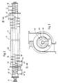
- a drying unit 5 of drying level T is in 2 and 3 in longitudinal or cross section on a larger scale.
- the drying unit 5 initially consists of an inner tube 40 in which a conveyor screw 42 rotates, driven by a drive 41, for example an electric motor.
- the screw conveyor 42 consists of an outer annular spiral 43 (FIG. 3) which is fastened via radial webs 44 to a shaft 45, which is shown here as a hollow shaft.
- the design of the helix 43 as a hollow helix has the advantage that the material can fall freely in the cavity formed in the inner tube 40 and can be transported.
- the material to be treated is fed to the inner pipe 40 on one side via a pipe socket 46 in free fall and drawn off at the other end via a pipe socket 47 in order to pass through the next drying unit.
- the inner tube 40 is surrounded by an outer jacket tube 48 over most of its length.
- an annular spiral 50 in the annular space 49 between the inner tube 40 and the outer jacket tube 48 there is an annular spiral 50, by means of which a helical annular channel 51 is formed in the annular space 49.
- the flue gas from the rotary kiln 24 is introduced as heating gas into this ring channel 51, parallel to the conveying direction of the material to be treated. This is done via a pipe socket 52 as an introduction and a pipe socket 53 as an outlet.
- Gas as a heat transfer medium has the best efficiency if it hits the heat transfer surface at high speed. If the flue gas used here as heating gas is pressed through this helical ring channel 52, its speed increases because of the small cross section, which improves the heat transfer.
- the helical routing of the heating gas channel results in a significantly longer effective treatment route, which e.g. with a pipe length of approx. 6 m, an extension of approx. 80 m is required; as a result, the heat content of the flue gas is used particularly well.
Landscapes
- Engineering & Computer Science (AREA)
- Chemical & Material Sciences (AREA)
- Mechanical Engineering (AREA)
- General Engineering & Computer Science (AREA)
- Oil, Petroleum & Natural Gas (AREA)
- Life Sciences & Earth Sciences (AREA)
- Organic Chemistry (AREA)
- Environmental & Geological Engineering (AREA)
- Hydrology & Water Resources (AREA)
- Water Supply & Treatment (AREA)
- Sustainable Development (AREA)
- Combustion & Propulsion (AREA)
- Materials Engineering (AREA)
- Treatment Of Sludge (AREA)
- Excavating Of Shafts Or Tunnels (AREA)
- Chemical Treatment Of Metals (AREA)
Description
- Die Erfindung betrifft ein Verfahren zur Behandlung von Klärschlamm, bei dem der Klärschlamm in aufeinanderfolgenden Behandlungsstufen zunächst getrocknet, danach einer Konvertierung unter anaeroben Bedingungen bei ca. 250 bis 350 Grad C unterzogen und schließlich bei mindestens 1.250 Grad C gebrannt wird, sowie eine Einrichtung zum Durchführen dieses Verfahrens.
- Klärschlamm ist ein nicht vermeidbares Produkt der biologischen Abwasserreinigung; seine Beseitigung ist mit zunehmender Problematik behaftet. Klärschlamm enthält je nach Behandlung und Zusammensetzung des Abwassers neben dem hauptsächlich aus Biomasse bakteriellen Ursprungs bestehenden organischen Anteil zwischen 20 bis 60 %, im Mittel etwa 50 % anorganische Bestandteile. Im Gegensatz zu pflanzlicher Biomasse kommen in Klärschlamm kaum Lipine und nur geringe Mengen Kohlehydrate, dafür aber als Hauptkomponenten Lipide und Proteine vor.
- Die in der Bundesrepublik Deutschland jährlich anfallende Menge an flüssigem Klärschlamm aus Haushalten und Industrie erhöht sich laufend; sie betrug z.B. im Jahr 1986 etwa 50 Millionen cbm mit etwa 4,6 % Gehalt an Trockenmasse. Von dieser Gesamtmenge kann nur etwa ein Drittel genutzt, d.h. entweder unmittelbar oder nach Kompostierung auf Landwirtschaftlich genutzte Flächen aufgebracht werden; der größte Teil des Klärschlammaufkommens wird als Abfall behandelt, wobei etwa 60 % unmittelbar deponiert und etwa 7 % thermisch behandelt und die Reststoffe deponiert werden.
- Abgesehen davon, daß das jährliche Aufkommen an Klärschlamm weiter zunehmen wird, weil weitere Teile der Bevölkerung an öffentliche Kläranlagensysteme angeschlossen werden und weil der geforderte Qualitätsgrad der Abwasserreinigung steigen wird, ist keine dieser Behandlungsarten unproblematisch. Dazu kommt, daß wegen der begrenzten Kapazität und der relativen Zunahme von Schadstoffen im Klärschlamm der Landwirtschaftlich verwertbare Anteil am Gesamtaufkommen absolut und relativ zurückgehen wird.
- Beim Recycling von Klärschlamm sind die Qualitätsanforderungen sehr hoch, vor allem im Hinblick auf Seuchenhygiene und chemische Inhaltsstoffe. Zur Aufbringung auf landwirtschaftlich genutzte Flächen muß Klärschlamm entseucht werden; das ist nur bei langer Einwirkzeit und/oder hoher Temperatur in einem biologischen, physikalischen oder chemischen Prozeß zu erreichen, nicht aber durch die übliche Klärschlammfaulung. Zudem hat Klärschlamm nicht nur einen relativ hohen Gehalt an giftigen Schwermetallen, sondern auch an Dioxin, so daß er nicht ohne weiteres als Landwirtschaftlicher Dünger verwertet werden kann.
- Neben der mit immer größeren Problemen behafteten Deponierung mechanisch entwässerter Klärschlämme gibt es verschiedene Ansätze zur thermischen Behandlung von Klärschlamm, um die darin enthaltene organische Materie als Energieträger nutzen zu können und nur die Reststoffe deponieren zu müssen.
- So ist es z.B. bekannt, Abfallstoffe, darunter auch Klärschlamm nach vorheriger Trocknung, in einer Hochtemperatur-Pyrolyse zu entgasen und das so gewonnene Pyrolysegas in einer nachgeschalteten Brennkammer zu verbrennen (EP 0 038 420 A1, DE 37 33 078 A1). Die dabei entstehenden Rauchgase können dabei als Heizgase zur Beheizung der Entgasungsanlage bzw. auch einer vorgeschalteten Trocknungsanlage verwendet werden; der Pyrolysekoks und die Asche aus der Gasverbrennung werden deponiert. Um auch die in Pyrolysekoks noch enthaltene chemisch gebundene Wärmeenergie nutzen zu können, ist es bekannt, auch diesen noch zu verbrennen (DE 28 55 510 B1). Auch hierbei werden die Verbrennungsabgase sowohl zur Beheizung der Entgasungsanlage, als auch der Trocknungsanlage eingesetzt; die verbleibende Asche wird deponiert.
- Auch bei einem Verfahren der eingangs angegebenen Art wird der Klärschlamm zunächst auf einen möglichst hohen Anteil an Trockensubstanz getrocknet (EP 0 347 808 A1). Danach wird der Klärschlamm zunächst einer Niedertemperatur-Konvertierung unter anaeroben Bedingungen bei etwa 250 bis 350 Grad C unterzogen, wobei der im Klärschlamm enthaltene organische Kohlenstoff in Form von öl ausgeschieden wird. Die danach verbleibenden Rückstände werden unter Zugabe von reinem Sauerstoff bei mindestens 1.250 Grad C gebrannt. Die danach verbleibenden anorganischen Bestandteile, die nur noch etwa 10 bis 15 % des ursprünglichen Klärschlammvolumens ausmachen, können entweder als Leichtzuschläge bei der Herstellung von Beton oder in fein gemahlenem Zustand als Substitut für ein hydraulisches Bindemittel, insbesondere Portlandzement, verwendet werden.
- Die Niedertemperatur-Konvertierung unter Luftabschluß ist ein Weg, die auf Erden sonst nicht direkt nachvollziehbare natürliche Erdölbildung nachzuahmen. Während in der Natur Kohle und Öl über lange Zeiträume und viele Zwischenstufen gebildet wurden, gelingt dies mit der Niedertemperatur-Konvertierung in kurzer Zeit. Es entstehen dabei aus Biopolymeren, wie Lipiden und Proteinen, Öle mit relativ hoher Verbrennungswärme; außerdem entsteht etwas Kohle. Ein weiterer wesentlicher Vorteil dieser Konvertierung besteht darin, daß bei den relativ mäßigen Temperaturen die Verflüchtigung toxischer Metalle nicht zu befürchten ist. Diese Art thermischer Behandlung grenzt sich somit von den Hochtemperatur-Pyrolysen ab, die nur zu Gasen und schwer verwertbaren Rückständen führen.
- Dieses bekannte Verfahren führt nicht nur zu einer vollständigen Nutzung der im Klärschlamm enthaltenen organischen Bestandteile, auch im Hinblick auf die darin enthaltene Energie, sondern auch dazu, daß die verbleibenden anorganischen Bestandteile nicht deponiert zu werden brauchen. Es hat den weiteren Vorteil, daß die Schwermetalle während der Be handlung nicht ausgeschieden werden, sondern in der anorganischen Restmasse verbleiben, in der sie nach der Sinterung in Form von Oxiden vorliegen, also in einer ihrem natürlichen Vorkommen entsprechenden Form, so daß keine Gefahr mehr besteht, daß sie etwa durch Auswaschen wieder in den Lebenskreislauf gelangen.
- Ein wesentlicher Vorteil dieses Verfahrens liegt aber auch darin, daß es durch sinnvolle Ausnutzung des hohen Energiegehaltes von Klärschlamm trotz des hohen Energiebedarfs eine weitgehend energieautarke, d.h. von der Zufuhr äußerer Energie weitgehend unabhängige Betriebsweise ermöglicht. Während dieses bekannte Verfahren gewissermaßen den theoretischen Hintergrund für ein bei weitestgehender Schonung der Umwelt praktisch vollständiges Recycling von Klärschlamm gibt, Liegt der Erfindung die Aufgabe zugrunde, eine Möglichkeit zu dessen praktischer Durchführung anzugeben.
- Nach der Erfindung wird diese Aufgabe durch ein Verfahren mit den im kennzeichnenden Teil des Patentanspruches 1 angegebenen Merkmalen sowie eine Einrichtung mit den Merkmalen des Patentanspruchs 4 gelöst.
- Vorteilhafte Weiterbildungen ergeben sich aus den Unteransprüchen.
- Verfahrensmäßig ermöglicht die Erfindung eine kontinuierliche Behandlung von vorentwässertem Klärschlamm unter Abscheidung der Zwischenpro- 30 dukte bis hin zur Sinterung der darin enthaltenen anorganischen Bestandteile in einem vollständig geschlossenen System; insbesondere dann, wenn dieses System unter einem leichten Unterdruck gehalten wird, besteht auch keine Gefahr, daß irgendwelche die Umwelt belastenden Schadstoffe emittiert werden.
- Durch die Verwendung der bei der Sinterung anfallenden Rauchgase für die Beheizung der Behandlungsstufen in der Reihenfolge des natürlicher- 40 weise eintretenden Temperaturabfalls wegen Abgabe der im Rauchgas enthaltenen Wärmemenge bis zu einer endseitigen Abgastemperatur von etwa 50 Grad C gelingt die Behandlung des Klärschlammes vom Energiebedarf her gesehen nahezu autark, d.h. die für die Behandlung erforderliche Ernergie wird weitgehend aus dem Brennwert der im Klärschlamm selbst enthaltenen organischen Bestandteile bezogen. Lediglich für die Sinterung ist die Zufuhr von reinem Sauerstoff erforderlich, wodurch unter Verbrennung der in dem Behandlungsgut nach der Konvertierungsstufe noch enthaltenen Kohle nicht nur die für die Sinterung der anorganischen Bestandteile erforderliche Temperatur erreicht, sondern auch die Verbrennung zusätzlicher, nicht regenerierbarer Energieträger vermieden wird. Dadurch wird nicht nur das Entstehen von weiterem Kohlendioxid, sondern vor allem von Stickoxiden vermieden, welche die Umwelt stark belasten.
- Der Vorteil der Einrichtung wird vor allem darin gesehen, daß durch die Hintereinanderschaltung der einzelnen Behandlungsstufen eine kompakte Anlage mit kurzen Förderstrecken entsteht. die in besonders vorteilhafter Weise mit Zwangsförderern bestückt werden, so daß Störungen im Durchlauf des Behandlungsgutes vermieden werden. Von Vorteil ist weiterhin, daß die Behandlung des Klärschlammes in den einzelnen Behandlungsstufen im Durchlaufverfahren erfolgt. so daß die eigentlichen Förderstrecken innerhalb der Anlage auf ein Minimum reduziert werden können.
- Die Erfindung wird nachstehend anhand der Zeichnung näher erläutert. Es zeigt
- Fig. 1
- eine schematische Darstellung einer Anlage zur Behandlung von Klärschlamm,
- Fig. 2
- einen Längschnitt durch eine Behandlungseinheit der Trockenstufe und
- Fig. 3
- einen Querschnitt entlang der Linie III-III in Fig. 1.
- Das erfindungsgemäße Verfahren und eine Einrichtung zu dessen Durchführung kann anhand der in Fig. 1 dargestellten schematischen übersicht erläutert werden.
- Die Anlage umfaßt zunächst eine Aufgabestation A mit einem Einlauftrichter 1 zur Aufgabe von mechanisch auf etwa 20 bis 30 % Trockensubstanz vorentwässertem Klärschlamm, der dann im Wege einer mechanischen Entwässerung noch weiter auf einen Feststoffgehalt von etwa 50 % entwässert werden kann.
- Das mechanisch vorentwässerte Material wird mittels einer Feststoffpumpe 2 über eine nur schematisch angedeutete Förderleitung 3 in Pfeilrichtung einer Trockenstufe T zugeführt, in der das Material wiederum in Pfeilrichtung mehrere, einander in einer Trockenbatterie 4 nachgeschaltete, beheizbare Trockeneinheiten 5 durchläuft; die Trokkeneinheiten 5 werden weiter unten noch näher erläutert. Aus der Trockenstufe T werden über eine Leitung 6 die Brüden abgezogen und einem Brüdenwäscher 7 sowie einem Kondensator 8 zugeführt. Aus dem Kondensator 8 gelangt das Kondensat in einen Auffangbehälter 9, aus dem es durch eine Kondensatpumpe 10 abgezogen werden kann. Ein an den Kondensator 8 angeschlossenes Gebläse 11 saugt die Gase ab und erzeugt gleichzeitig einen Unterdruck im gesamten System.
- Das Behandlungsgut, das die Trockenstufe T durchlaufen hat, gelangt dann über einen Zwischenförderer 12, der zweckmäßigerweise als zwangsweise fördernde Doppelschnecke ausgebildet ist, zur Konvertierungsstufe K. In die Konvertierungsstufe K gelangt das Material über einen Eintrag 13, der ebenfalls eine zwangsweise fördernde Doppelschnecke aufweist, durch die das Behandlungsgut in Pfeilrichtung in den eigentlichen Konverter 14 transportiert wird.
- In dem Konverter 14, den das Behandlungsgut mittels einer durch einen Antrieb 15 angetriebenen Fördereinrichtung, vorzugsweise wieder einer zwangsweise fördernden Doppelschnecke, durchläuft, wird das Behandlungsgut auf eine Temperatur von etwa 250 bis 350 Grad C aufgeheizt. Da im Konverter anaerobe Bedingungen aufrechterhalten werden müssen, muß die Fördereinrichtung an den Enden abgedichtet sein. Bei dieser sogenannten Niedertemperatur-Konvertierung unter anaeroben Bedingungen entstehen analog der Bildung von Erdöl und Kohle in der Natur aus den im Klärschlamm enthaltenen Lipiden und Proteinen Öle mit einem verhältnismäßig hohen Kohlenstoffanteil und hoher Verbrennungswärme, daneben Kohle.
- Die Konversionsgase werden aus dem Konverter 14 über eine Leitung 16 abgeschieden und einem Kondensator 17 zugeführt. Das bei der Kondensation entstehende Öl kann über eine Ölpumpe 18 abgezogen werden; die Restgase werden über eine Leitung 19 wieder in den Konverter 14 zurückgeführt. Ein etwa entstehender überdruck kann über ein überdruckventil 20 und eine Leitung 21 unmittelbar in die nachgeschaltete Sinterstufe S übergeführt werden.
- Das in der Konvertierungsstufe K von den flüchtigen organischen Bestandteilen befreite Material gelangt dann über einen Austrag 22 und gegebenenfalls einen weiteren Zwischenförderer 23 zur Sinterstufe S. Die Sinterstufe S umfaßt einen Drehrohrofen 24 üblicher Bauart, in den auf der Eingangsseite 25 die Rückstände der Niedertemperatur-Konvertierung eingetragen werden. Der Drehrohrofen 24 ist an der Ausgangsseite 26 mit einem Gas-Sauerstoff-Brenner 27 ausgestattet; eingangsseitig ist über eine Lanze 28 reiner Sauerstoff zuführbar. Unter Zuführung von reinem Sauerstoff verbrennt die in dem Material noch enthaltene Restkohle bei einer Temperatur von 1.250 bis etwa 1.400 Grad C, wodurch eine Sinterung der dann allein noch vorhandenen anorganischen Bestandteile des Materials eintritt. Das gesinterte Endprodukt gelangt über einen Austrag 29 in einen Behälter 30, aus dem es abgezogen werden kann.
- Parallel zu dem vorbeschriebenen Weg des Behandlungsgutes ist der Weg des bei der Sinterung im Drehrohrofen 24 entstehenden Rauchgases. Das Rauchgas wird aus dem Ofen 24 über eine Leitung 31 abgezogen und über einen Zyklon 32 zur Staubabscheidung und eine Leitung 33 zunächst in den Konverter 14 geführt. Das Rauchgas tritt an derselben Seite wie das Behandlungsgut mit einer Temperatur von etwa 400 Grad C in den Konverter 14 ein, umstreicht eine in seinem Inneren angeordnete Behandlungseinheit und verläßt den Konverter 14 wieder über eine Leitung 34 mit einer Temperatur von etwa 250 Grad C. Die Heizgasführung im Konverter 14 erfolgt in gleicher Weise wie bei den Trockeneinheiten 5, die weiter unten noch beschrieben werden.
- Über die Leitung 34, die mit der Leitung 33 gegebenenfalls durch eine Bypassklappe 35 verbunden werden kann, gelangt das Rauchgas dann in die erste der Trockeneinheiten 5 der Trockenstufe T, die es in einer weiter unten noch zu erläuternden Weise durchströmt. In jeder der Trockeneinheiten 5 verringert sich die Rauchgastemperatur größenordnungsmäßig um 50 Grad C, so daß es am Ende beim Verlassen der Trockenstufe T noch eine Temperatur von etwa 50 Grad C hat. Über eine Abgasleitung 36 wird das Abgas dann einer üblichen Abgasreinigung zugeführt.
- Eine Trockeneinheit 5 der Trockenstufe T ist in den Fig. 2 und 3 im Längs- bzw. Querschnitt in größerem Maßstab dargestellt. Die Trockeneinheit 5 besteht zunächst aus einem Innenrohr 40, in dem durch einen Antrieb 41, z.B. einen Elektromotor, angetrieben eine Förderschnecke 42 umläuft. Die Förderschnecke 42 besteht aus einer äußeren ringförmigen Wendel 43 (Fig. 3), die über radiale Stege 44 an einer Welle 45 befestigt ist, die hier als Hohlwelle dargestellt.ist. Die Ausbildung der Wendel 43 als Hohlwendel hat den Vorteil, daß das Material in dem in dem Innenrohr 40 gebildeten Hohlraum frei fallen und transportiert werden kann. Das Behandlungsgut wird dem Innenrohr 40 an der einen Seite über einen Rohrstutzen 46 in freiem Fall zugeführt und am anderen Ende über einen Rohrstutzen 47 abgezogen, um die nächste Trokkeneinheit zu durchlaufen.
- Über den größten Teil seiner Länge ist das Innenrohr 40 von einem äußeren Mantelrohr 48 umgeben. In dem Ringraum 49 zwischen dem Innenrohr 40 und dem äußeren Mantelrohr 48 befindet sich eine ringförmige Wendel 50, durch die in dem Ringraum 49 ein wendelförmiger Ringkanal 51 gebildet wird. In diesen Ringkanal 51 wird - parallel zu der Förderrichtung des Behandlungsgutes - das Rauchgas aus dem Drehrohrofen 24 als Heizgas eingeleitet. Dies geschieht über einen Rohrstutzen 52 als Einleitung und einen Rohrstutzen 53 als Ausleitung.
- Gas als Wärmeträger hat den besten Wirkungsgrad, wenn es mit hoher Geschwindigkeit auf die Wärmeübergangsfläche auftrifft. Wenn das hier als Heizgas verwendete Rauchgas durch diesen wendelförmigen Ringkanal 52 gepreßt wird, erhöht sich wegen des geringen Querschnitts seine Geschwindigkeit, wodurch der Wärmeübergang verbessert wird.
- Außerdem ergibt sich durch die wendelförmige Führung des Heizgaskanals eine wesentlich längere wirksame Behandlungsstrecke, die z.B. bei einer Rohrlänge von ca. 6 m eine Verlängerung von ca. 80 m ausmacht; dadurch wird der Wärmeinhalt des Rauchgases besonders gut genutzt.
- Es ist selbstverständlich, daß nicht nur die Einheiten in den einzelnen Behandlungsstufen, sondern auch die Förderleitungen für das Rauchgas wärmegedämmt werden, um einerseits eine Wärmeabgabe an die Umwelt zu vermeiden und andererseits den Wärmeinhalt des Rauchgases möglichst vollständig als Prozeßwärme nutzen zu können.
Claims (12)
- Verfahren zur Behandlung von Klärschlamm, bei dem der Klärschlamm in aufeinanderfolgenden Behandlungsstufen zunächst getrocknet, danach einer Konvertierung unter anaeroben Bedingungen bei ca. 250 bis 350 Grad C unterzogen und schließlich bei mindestens 1.250 Grad C gebrannt wird, dadurch gekennzeichnet,
daß alle Verfahrensschritte einschließlich der Forderung des Behandlungsgutes zwischen den einzelnen Behandlungsstufen in kontinuierlichem Durchlauf nacheinander in einem geschlossenen System durchgeführt werden, aus dem lediglich in der Trockenstufe (T) die Brüden und in der Konvertierungsstufe (K) das Konversionsgas abgeführt und kondensiert werden,
daß das beim Brennen anfallende Rauchgas in kontinuierlichem Strom zum Beheizen zunächst der Einrichtungen zum Konvertieren und danach der Einrichtungen zum Trocknen verwendet wird,
wobei der Rauchgasstrom innerhalb der jeweiligen Einrichtungen parallel zur Förderrichtung des Behandlungsgutes geführt wird, so daß jeweils am Beginn der jeweiligen Behandlungsstufe die höchste Rauchgastemperatur zur Beheizung zur Verfügung steht. - Verfahren nach Anspruch 1 dadurch gekennzeichnet, daß in dem gesamten Behandlungs- und Fördersystem ein leichter Unterdruck aufrechterhalten wird.
- Verfahren nach Anspruch 1 oder 2, dadurch gekennzeichnet, daß das Behandlungsgut auf den Förderstrecken zwischen den einzelnen Behandlungsstufen zwangsweise gefördert wird, z.B. mittels Schneckenförderer.
- Einrichtung zum Durchführen des Verfahrens gemäß Anspruch 1, gekennzeichnet durch folgende Vorrichtungsmerkmale:- eine Aufgabestation (A) zur Aufgabe von mechanisch vorentwässertem Klärschlamm,- eine Trockenstufe (T) mit mindestens einer durch Heizgas beheizbaren rohrförmigen Behandlungseinheit und mit Vorrichtungen zur kontinuierlichen Forderung des Behandlungsgutes,- eine Konvertierungsstufe (K) mit mindestens einer durch Heizgas beheizbaren rohrförmigen Behandlungseinheit und mit Vorrichtungen zur kontinuierlichen Förderung des Behandlungsgutes,- eine Sinterstufe (S) mit einem Drehrohrofen mit einem Austrag für die Schlacke,- geschlossene Leitungen zur kontinuierlichen Forderung des Behandlungsgutes zwischen der Aufgabestation (A), den Behandlungseinheiten der Trockenstufe (T) und der Konvertierungsstufe (K) sowie dem Drehrohrofen der Sinterstufe (S),- Leitungen zur Forderung des in der Sinterstufe (S) anfallenden Rauchgases als Heizgas zunächst zu den Behandlungseinheiten der Konvertierungsstufe (K) und danach zu denjenigen der Trockenstufe (T) sowie- eine Leitung (6) zur Abführung der Brüden aus der Trockenstufe (T) zu einem Kondensator (8) und eine Leitung (16) zur Abführung des Konversionsgases aus der Konvertierungsstufe (K) zu einem Kondensator (17).
- Einrichtung nach Anspruch 4, dadurch gekennzeichnet, daß der Trockenstufe (T) eine Vorrichtung zur mechanischen Entwässerung des Klärschlammes vorgeschaltet ist.
- Einrichtung nach Anspruch 4 oder 5, dadurch gekennzeichnet, daß zur Förderung des Behandlungsgutes zwischen den Behandlungsstufen Zwangsförderer, z.B. Doppelschneckenförderer, vorgesehen sind.
- Einrichtung nach einem der Ansprüche 4 bis 6, dadurch gekennzeichnet, daß in der Trockenstufe (T) mehrere Behandlungseinheiten (5) hintereinander angeordnet und zur Förderung des Behandlungsgutes jeweils an den Enden miteinander verbunden sind.
- Einrichtung nach einem der Ansprüche 4 bis 7, dadurch gekennzeichnet, daß die Behandlungseinheiten (5) mit jeweils umgekehrter Förderrichtung übereinander zu einer Trockenbatterie (4) zusammengefaßt sind.
- Einrichtung nach einem der Ansprüche 4 bis 8, dadurch gekennzeichnet, daß jede Behandlungseinheit (5) der Trockenstufe (T) aus einem inneren Förderrohr (40) für das Behandlungsgut besteht, in dem eine Förderschnecke (42) drehbar angeordnet ist und daß das Förderrohr (40) von einem äußeren Mantelrohr (48) umgeben ist, wobei der zwischen dem Förderrohr (40) und dem Mantelrohr (48) gebildete ringförmige Hohlraum (49) durch Heizgas beaufschlagbar ist.
- Einrichtung nach Anspruch 9, dadurch gekennzeichnet, daß in dem ringförmigen Hohlraum (49) durch eine diesen in Querrichtung abschließende ringförmige Wendel (50) ein wendelförmiger Heizkanal (51) gebildet ist.
- Einrichtung nach einem der Ansprüche 4 bis 10, dadurch gekennzeichnet, daß die Förderschnecke (42) aus einer ringförmigen Wendel (43) besteht, die durch radiale Stege (44) an einer zentral angetriebenen Achse (45) befestigt ist.
- Einrichtung nach einem der Ansprüche 4 bis 11, dadurch gekennzeichnet, daß am Außenumfang des Mantelrohres (48) eine wärmedämmende Ummantelung angeordnet ist.
Priority Applications (9)
| Application Number | Priority Date | Filing Date | Title |
|---|---|---|---|
| ES90116810T ES2050900T3 (es) | 1990-09-01 | 1990-09-01 | Procedimiento y dispositivo para el tratamiento de lodo de clarificacion. |
| AT90116810T ATE101587T1 (de) | 1990-09-01 | 1990-09-01 | Verfahren und einrichtung zur behandlung von klaerschlamm. |
| DE90116810T DE59004634D1 (de) | 1990-09-01 | 1990-09-01 | Verfahren und Einrichtung zur Behandlung von Klärschlamm. |
| EP19900116810 EP0474890B1 (de) | 1990-09-01 | 1990-09-01 | Verfahren und Einrichtung zur Behandlung von Klärschlamm |
| DK90116810T DK0474890T3 (da) | 1990-09-01 | 1990-09-01 | Fremgangsmåde og indretning til behandling af rensningsslam |
| US07/734,197 US5246599A (en) | 1990-09-01 | 1991-07-22 | Method and arrangement for treatment of sewage sludge |
| SU5001263 RU2040490C1 (ru) | 1990-09-01 | 1991-08-20 | Способ обработки активного ила и установка для его осуществления |
| PL91291545A PL166190B1 (pl) | 1990-09-01 | 1991-08-28 | Sposób obróbki osadu sciekowego i urzadzenie do obróbki osadu sciekowego PL |
| HU912831A HU212287B (en) | 1990-09-01 | 1991-08-30 | Method and apparatus for treating sewage water sludge |
Applications Claiming Priority (1)
| Application Number | Priority Date | Filing Date | Title |
|---|---|---|---|
| EP19900116810 EP0474890B1 (de) | 1990-09-01 | 1990-09-01 | Verfahren und Einrichtung zur Behandlung von Klärschlamm |
Publications (2)
| Publication Number | Publication Date |
|---|---|
| EP0474890A1 EP0474890A1 (de) | 1992-03-18 |
| EP0474890B1 true EP0474890B1 (de) | 1994-02-16 |
Family
ID=8204408
Family Applications (1)
| Application Number | Title | Priority Date | Filing Date |
|---|---|---|---|
| EP19900116810 Expired - Lifetime EP0474890B1 (de) | 1990-09-01 | 1990-09-01 | Verfahren und Einrichtung zur Behandlung von Klärschlamm |
Country Status (9)
| Country | Link |
|---|---|
| US (1) | US5246599A (de) |
| EP (1) | EP0474890B1 (de) |
| AT (1) | ATE101587T1 (de) |
| DE (1) | DE59004634D1 (de) |
| DK (1) | DK0474890T3 (de) |
| ES (1) | ES2050900T3 (de) |
| HU (1) | HU212287B (de) |
| PL (1) | PL166190B1 (de) |
| RU (1) | RU2040490C1 (de) |
Cited By (1)
| Publication number | Priority date | Publication date | Assignee | Title |
|---|---|---|---|---|
| EP1384948A1 (de) | 2002-07-23 | 2004-01-28 | Norsk Inova AS | Verfahren und Einrichtung zur Abfallverarbeitung, insbesondere von feuchtem Abfall in einem Verbrennungsofen |
Families Citing this family (21)
| Publication number | Priority date | Publication date | Assignee | Title |
|---|---|---|---|---|
| DE4230679A1 (de) * | 1992-09-14 | 1994-03-17 | Bayer Ag | Verfahren zur kontinuierlichen Klärschlammtrocknung |
| KR960009388B1 (ko) * | 1992-11-30 | 1996-07-18 | 최훈 | 슬러지 건조 고형분 처리방법 |
| US5647980A (en) * | 1994-06-06 | 1997-07-15 | Smith; Carole M. | Apparatus and method for treating waste water from a residential home |
| BE1013570A4 (nl) * | 2000-06-22 | 2002-04-02 | Biocalor Bvba | Inrichting en werkwijze voor het drogen van een waterhoudende massa, zoals mest en dergelijke. |
| WO2005003663A2 (en) * | 2003-07-01 | 2005-01-13 | Inetec Limited | Organic waste disposal |
| GR1006855B (el) * | 2005-01-14 | 2010-07-06 | Σοφια Μπεθανη | Δομικα υλικα με χρηση αδρανων απο στερεα αποβλητα |
| US7655088B2 (en) | 2005-01-14 | 2010-02-02 | Alkemy, Ltd. | Synthetic aggregates comprising sewage sludge and other waste materials and methods for producing such aggregates |
| US7780781B2 (en) * | 2005-01-14 | 2010-08-24 | Alkemy, Ltd. | Pyroprocessed aggregates comprising IBA and low calcium silicoaluminous materials and methods for producing such aggregates |
| RU2446371C2 (ru) * | 2010-06-09 | 2012-03-27 | Научно-производственная фирма с ограниченной ответственностью "Экополимер" | Устройство для сушки осадка, активного ила или отстоя промышленных и бытовых сточных вод |
| DE102012103798A1 (de) * | 2012-04-30 | 2013-10-31 | Max Aicher Bau GmbH & Co. KG | Schlackenbeet |
| RU2532198C1 (ru) * | 2013-03-27 | 2014-10-27 | Общество С Ограниченной Ответственностью "Активил" | Способ получения фосфорсодержащего удобрения из илового осадка городских водоочистных сооружений и удобрение, полученное таким способом |
| GB2536050B (en) * | 2015-03-05 | 2017-04-26 | Standard Gas Ltd | Temperature profile in an advanced thermal treatment apparatus and method |
| SG10201502704VA (en) * | 2015-04-07 | 2016-11-29 | Singnergy Corp Pte Ltd | Apparatus and method for improved evaporation drying |
| EP3361198A1 (de) * | 2017-02-13 | 2018-08-15 | Danmarks Tekniske Universitet | Schlämmetrocknungsanlage, verfahren zur trocknung von schlämme und verwendung einer schlämmetrocknungsanlage |
| CN107036106B (zh) * | 2017-04-21 | 2019-01-18 | 俞俊宇 | 一种污泥焚烧用泥土加油器 |
| RU2674125C1 (ru) * | 2017-12-19 | 2018-12-04 | Федеральное государственное бюджетное образовательное учреждение высшего образования "Юго-Западный государственный университет" (ЮЗГУ) | Устройство для термической обработки осадка сточных вод предприятий аграрно-промышленного комплекса |
| JP6886757B2 (ja) * | 2018-01-29 | 2021-06-16 | 大河 澄男 | 高含水バイオマス資源の乾燥装置および乾燥方法 |
| CN108249720B (zh) * | 2018-03-13 | 2020-06-16 | 山东金孚环境工程有限公司 | 一种机械脱水耦合干化热解制备污泥炭的方法 |
| CN108579384B (zh) * | 2018-05-10 | 2021-08-17 | 哈尔滨工业大学 | 一种复合干化与焚烧耦合发电的污泥处理装置 |
| RU2704398C1 (ru) * | 2019-03-25 | 2019-10-28 | Общество С Ограниченной Ответственностью "Научно-Технический Центр "Экопромтех" | Способ остеклования илового осадка или других органических шламов и отходов и устройство для его реализации |
| CN112028448B (zh) * | 2020-09-21 | 2024-06-18 | 清华大学 | 一种污泥处理与建材资源化利用系统及工艺 |
Family Cites Families (15)
| Publication number | Priority date | Publication date | Assignee | Title |
|---|---|---|---|---|
| US3275547A (en) * | 1964-07-20 | 1966-09-27 | Bucksteeg Wilhelm | Method of treating sewage |
| US3875357A (en) * | 1971-08-17 | 1975-04-01 | Babcock & Wilcox Co | Sewage disposal system |
| US3803806A (en) * | 1972-09-28 | 1974-04-16 | Komline Sanderson Eng Corp | Process for the treatment of activated sludge |
| AR205469A1 (es) * | 1974-07-04 | 1976-05-07 | Kiener Karl | Procedimiento y dispositivo de obtencion de gas combustible |
| US4013516A (en) * | 1975-03-13 | 1977-03-22 | Hanover Research Corporation | Apparatus and process for the pyrolysis of waste solids concentrates |
| DE2651302C3 (de) * | 1976-05-12 | 1981-07-09 | PLS Gesellschaft für Pyrolyse-Müllverwertungsverfahren mbH, 8000 München | Vorrichtung zur Destillationsgaserzeugung aus Abfall |
| DE2855510B1 (de) * | 1978-12-22 | 1980-04-17 | Peter Voelskow | Verfahren und Anlage zur thermischen Verwertung von Abfaellen |
| DE3015290A1 (de) * | 1980-04-21 | 1981-10-29 | Werner & Pfleiderer, 7000 Stuttgart | Verfahren und anlage zum veraschen von klaerschlamm |
| CA1225062A (en) * | 1983-09-13 | 1987-08-04 | Trevor R. Bridle | Processes and apparatus for the conversion of sludges |
| DE3423620A1 (de) * | 1984-06-27 | 1986-01-02 | Uhde Gmbh, 4600 Dortmund | Verfahren zur thermischen behandlung von kohlenstoffhaltigen stoffen, insbesondere von schlaemmen |
| DE3733078C2 (de) * | 1987-09-30 | 1996-10-02 | Siemens Ag | Anlage zur thermischen Abfallbeseitigung |
| DE3735906A1 (de) * | 1987-10-23 | 1989-05-18 | Kloeckner Humboldt Deutz Ag | Verfahren zur thermischen entsorgung organischer oder organisch-kontaminierter abfallstoffe |
| EP0343431B1 (de) * | 1988-05-24 | 1993-08-25 | Siemens Aktiengesellschaft | Verfahren und Einrichtung zum Trocknen von Klärschlamm |
| DE58902128D1 (de) * | 1988-06-21 | 1992-10-01 | Aicher Max | Verfahren zur behandlung von klaerschlamm. |
| JPH02253900A (ja) * | 1989-03-29 | 1990-10-12 | Masaaki Tachiki | 汚泥の処理方法 |
-
1990
- 1990-09-01 ES ES90116810T patent/ES2050900T3/es not_active Expired - Lifetime
- 1990-09-01 EP EP19900116810 patent/EP0474890B1/de not_active Expired - Lifetime
- 1990-09-01 DK DK90116810T patent/DK0474890T3/da active
- 1990-09-01 AT AT90116810T patent/ATE101587T1/de not_active IP Right Cessation
- 1990-09-01 DE DE90116810T patent/DE59004634D1/de not_active Expired - Fee Related
-
1991
- 1991-07-22 US US07/734,197 patent/US5246599A/en not_active Expired - Fee Related
- 1991-08-20 RU SU5001263 patent/RU2040490C1/ru active
- 1991-08-28 PL PL91291545A patent/PL166190B1/pl unknown
- 1991-08-30 HU HU912831A patent/HU212287B/hu not_active IP Right Cessation
Cited By (1)
| Publication number | Priority date | Publication date | Assignee | Title |
|---|---|---|---|---|
| EP1384948A1 (de) | 2002-07-23 | 2004-01-28 | Norsk Inova AS | Verfahren und Einrichtung zur Abfallverarbeitung, insbesondere von feuchtem Abfall in einem Verbrennungsofen |
Also Published As
| Publication number | Publication date |
|---|---|
| HUT69488A (en) | 1995-09-28 |
| PL166190B1 (pl) | 1995-04-28 |
| EP0474890A1 (de) | 1992-03-18 |
| ATE101587T1 (de) | 1994-03-15 |
| PL291545A1 (en) | 1992-06-26 |
| DE59004634D1 (de) | 1994-03-24 |
| HU212287B (en) | 1996-05-28 |
| US5246599A (en) | 1993-09-21 |
| ES2050900T3 (es) | 1994-06-01 |
| RU2040490C1 (ru) | 1995-07-25 |
| HU912831D0 (en) | 1992-01-28 |
| DK0474890T3 (da) | 1994-07-11 |
Similar Documents
| Publication | Publication Date | Title |
|---|---|---|
| EP0474890B1 (de) | Verfahren und Einrichtung zur Behandlung von Klärschlamm | |
| EP0038420B1 (de) | Verfahren und Anlage zum Veraschen von Klärschlamm | |
| DE69112831T2 (de) | Verfahren und vorrichtung für die schlammtrocknung. | |
| EP0343431B1 (de) | Verfahren und Einrichtung zum Trocknen von Klärschlamm | |
| DE19614689C2 (de) | Multivalent einsetzbare Anlage zur thermischen Behandlung von Ausgangssubstanzen | |
| DE3347554C2 (de) | Verfahren zur Gewinnung von verwertbarem Gas aus Müll durch Pyrolyse und Vorrichtung zum Durchführen des Verfahrens | |
| EP0461305B1 (de) | Verfahren zur Reinigung der Abgase von Anlagen zur Herstellung von Zementklinker | |
| EP0263338A2 (de) | Pyrolyseanlage | |
| EP0436822B2 (de) | Verfahren zur Reinigung der Abgase von Anlagen zur Herstellung von Zementklinker | |
| EP0254024B1 (de) | Verfahren zum Konvertieren von Klärschlamm-Filterkuchen durch Pyrolyse zu Öl, Gas und Koks und Anlage zur Durchführung des Verfahrens | |
| DE2800030C3 (de) | Verfahren zur Umsetzung von Naßabfall durch Pyrolyse | |
| EP0241657B1 (de) | Abfallbeseitigungseinrichtung für Problemstoffe | |
| DE102009007768A1 (de) | Vorrichtung in Form eines Thermolysereaktors und Verfahren zum Betreiben eines solchen in einer Anordnung zur thermischen Zersetzung von Abprodukten und Abfällen | |
| DE4309283A1 (de) | Vorrichtung zur Abfallaufbereitung | |
| EP0347808B1 (de) | Verfahren zur Behandlung von Klärschlamm | |
| DE3513541C2 (de) | ||
| DE3238328A1 (de) | Verfahren zur aufarbeitung von einen heizwert aufweisenden schlammfoermigen abwasserrueckstaenden sowie anlage zur durchfuehrung des verfahrens | |
| EP0094547B1 (de) | Anlage zur Beseitigung von Sickerwasser und Faulgas in Abfalldeponien | |
| DE2951620A1 (de) | Verfahren und vorrichtung zur verwertung von muell und/oder abwasserschlamm | |
| EP1378494B1 (de) | Verfahren und Vorrichtung zur Verarbeitung biogener Reststoffe, insbesondere von Schlämmen | |
| DE19729585C1 (de) | Vorrichtung zur thermischen Entsorgung von Klärschlamm | |
| EP1274656A1 (de) | Konditionierungsverfahren biogener feststoffe | |
| DE2535683A1 (de) | Verfahren und vorrichtung zur verbrennung von schlaemmen mit hilfe rekuperativer schlammtrocknung | |
| EP1081101A1 (de) | Verfahren und Vorrichtung zum Trocknen von Klärschlamm | |
| AT411254B (de) | Verfahren und vorrichtung zur verarbeitung biogener reststoffe, insbesondere von schlämmen |
Legal Events
| Date | Code | Title | Description |
|---|---|---|---|
| PUAI | Public reference made under article 153(3) epc to a published international application that has entered the european phase |
Free format text: ORIGINAL CODE: 0009012 |
|
| 17P | Request for examination filed |
Effective date: 19910711 |
|
| AK | Designated contracting states |
Kind code of ref document: A1 Designated state(s): AT BE CH DE DK ES FR GB GR IT LI LU NL SE |
|
| 17Q | First examination report despatched |
Effective date: 19920325 |
|
| GRAA | (expected) grant |
Free format text: ORIGINAL CODE: 0009210 |
|
| AK | Designated contracting states |
Kind code of ref document: B1 Designated state(s): AT BE CH DE DK ES FR GB GR IT LI LU NL SE |
|
| REF | Corresponds to: |
Ref document number: 101587 Country of ref document: AT Date of ref document: 19940315 Kind code of ref document: T |
|
| REF | Corresponds to: |
Ref document number: 59004634 Country of ref document: DE Date of ref document: 19940324 |
|
| ITF | It: translation for a ep patent filed | ||
| REG | Reference to a national code |
Ref country code: ES Ref legal event code: FG2A Ref document number: 2050900 Country of ref document: ES Kind code of ref document: T3 |
|
| ET | Fr: translation filed | ||
| GBT | Gb: translation of ep patent filed (gb section 77(6)(a)/1977) |
Effective date: 19940517 |
|
| REG | Reference to a national code |
Ref country code: DK Ref legal event code: T3 |
|
| REG | Reference to a national code |
Ref country code: GR Ref legal event code: FG4A Free format text: 3011767 |
|
| PLBE | No opposition filed within time limit |
Free format text: ORIGINAL CODE: 0009261 |
|
| STAA | Information on the status of an ep patent application or granted ep patent |
Free format text: STATUS: NO OPPOSITION FILED WITHIN TIME LIMIT |
|
| EAL | Se: european patent in force in sweden |
Ref document number: 90116810.4 |
|
| 26N | No opposition filed | ||
| PGFP | Annual fee paid to national office [announced via postgrant information from national office to epo] |
Ref country code: DE Payment date: 20000811 Year of fee payment: 11 |
|
| PGFP | Annual fee paid to national office [announced via postgrant information from national office to epo] |
Ref country code: GB Payment date: 20000814 Year of fee payment: 11 |
|
| PGFP | Annual fee paid to national office [announced via postgrant information from national office to epo] |
Ref country code: FR Payment date: 20000918 Year of fee payment: 11 |
|
| PGFP | Annual fee paid to national office [announced via postgrant information from national office to epo] |
Ref country code: SE Payment date: 20000921 Year of fee payment: 11 |
|
| PGFP | Annual fee paid to national office [announced via postgrant information from national office to epo] |
Ref country code: LU Payment date: 20000922 Year of fee payment: 11 Ref country code: ES Payment date: 20000922 Year of fee payment: 11 Ref country code: DK Payment date: 20000922 Year of fee payment: 11 Ref country code: CH Payment date: 20000922 Year of fee payment: 11 Ref country code: BE Payment date: 20000922 Year of fee payment: 11 Ref country code: AT Payment date: 20000922 Year of fee payment: 11 |
|
| PGFP | Annual fee paid to national office [announced via postgrant information from national office to epo] |
Ref country code: NL Payment date: 20000926 Year of fee payment: 11 |
|
| PGFP | Annual fee paid to national office [announced via postgrant information from national office to epo] |
Ref country code: GR Payment date: 20000928 Year of fee payment: 11 |
|
| PG25 | Lapsed in a contracting state [announced via postgrant information from national office to epo] |
Ref country code: LU Free format text: LAPSE BECAUSE OF NON-PAYMENT OF DUE FEES Effective date: 20010901 Ref country code: GB Free format text: LAPSE BECAUSE OF NON-PAYMENT OF DUE FEES Effective date: 20010901 Ref country code: DK Free format text: LAPSE BECAUSE OF NON-PAYMENT OF DUE FEES Effective date: 20010901 Ref country code: AT Free format text: LAPSE BECAUSE OF NON-PAYMENT OF DUE FEES Effective date: 20010901 |
|
| PG25 | Lapsed in a contracting state [announced via postgrant information from national office to epo] |
Ref country code: SE Free format text: LAPSE BECAUSE OF NON-PAYMENT OF DUE FEES Effective date: 20010902 Ref country code: ES Free format text: LAPSE BECAUSE OF NON-PAYMENT OF DUE FEES Effective date: 20010902 |
|
| PG25 | Lapsed in a contracting state [announced via postgrant information from national office to epo] |
Ref country code: LI Free format text: LAPSE BECAUSE OF NON-PAYMENT OF DUE FEES Effective date: 20010930 Ref country code: GR Free format text: LAPSE BECAUSE OF NON-PAYMENT OF DUE FEES Effective date: 20010930 Ref country code: CH Free format text: LAPSE BECAUSE OF NON-PAYMENT OF DUE FEES Effective date: 20010930 Ref country code: BE Free format text: LAPSE BECAUSE OF NON-PAYMENT OF DUE FEES Effective date: 20010930 |
|
| BERE | Be: lapsed |
Owner name: AICHER MAX Effective date: 20010930 |
|
| PG25 | Lapsed in a contracting state [announced via postgrant information from national office to epo] |
Ref country code: NL Free format text: LAPSE BECAUSE OF NON-PAYMENT OF DUE FEES Effective date: 20020401 |
|
| PG25 | Lapsed in a contracting state [announced via postgrant information from national office to epo] |
Ref country code: DE Free format text: LAPSE BECAUSE OF NON-PAYMENT OF DUE FEES Effective date: 20020501 |
|
| EUG | Se: european patent has lapsed |
Ref document number: 90116810.4 |
|
| REG | Reference to a national code |
Ref country code: CH Ref legal event code: PL |
|
| PG25 | Lapsed in a contracting state [announced via postgrant information from national office to epo] |
Ref country code: FR Free format text: LAPSE BECAUSE OF NON-PAYMENT OF DUE FEES Effective date: 20020531 |
|
| NLV4 | Nl: lapsed or anulled due to non-payment of the annual fee |
Effective date: 20020401 |
|
| REG | Reference to a national code |
Ref country code: DK Ref legal event code: EBP |
|
| REG | Reference to a national code |
Ref country code: FR Ref legal event code: ST |
|
| NLV4 | Nl: lapsed or anulled due to non-payment of the annual fee |
Effective date: 20020401 |
|
| REG | Reference to a national code |
Ref country code: ES Ref legal event code: FD2A Effective date: 20021011 |
|
| PG25 | Lapsed in a contracting state [announced via postgrant information from national office to epo] |
Ref country code: IT Free format text: LAPSE BECAUSE OF NON-PAYMENT OF DUE FEES Effective date: 20050901 |