EP0473859A1 - Wand zur Absorption der Ausstrahlung und Verfahren zur Absorption der Ausstrahlung und Übertragung der Wärmeenergie in Solarwänden - Google Patents
Wand zur Absorption der Ausstrahlung und Verfahren zur Absorption der Ausstrahlung und Übertragung der Wärmeenergie in Solarwänden Download PDFInfo
- Publication number
- EP0473859A1 EP0473859A1 EP90630146A EP90630146A EP0473859A1 EP 0473859 A1 EP0473859 A1 EP 0473859A1 EP 90630146 A EP90630146 A EP 90630146A EP 90630146 A EP90630146 A EP 90630146A EP 0473859 A1 EP0473859 A1 EP 0473859A1
- Authority
- EP
- European Patent Office
- Prior art keywords
- wall section
- massive
- wall
- fluid
- insulation layer
- Prior art date
- Legal status (The legal status is an assumption and is not a legal conclusion. Google has not performed a legal analysis and makes no representation as to the accuracy of the status listed.)
- Withdrawn
Links
Images


Classifications
-
- F—MECHANICAL ENGINEERING; LIGHTING; HEATING; WEAPONS; BLASTING
- F24—HEATING; RANGES; VENTILATING
- F24S—SOLAR HEAT COLLECTORS; SOLAR HEAT SYSTEMS
- F24S20/00—Solar heat collectors specially adapted for particular uses or environments
- F24S20/60—Solar heat collectors integrated in fixed constructions, e.g. in buildings
- F24S20/66—Solar heat collectors integrated in fixed constructions, e.g. in buildings in the form of facade constructions, e.g. wall constructions
-
- F—MECHANICAL ENGINEERING; LIGHTING; HEATING; WEAPONS; BLASTING
- F24—HEATING; RANGES; VENTILATING
- F24S—SOLAR HEAT COLLECTORS; SOLAR HEAT SYSTEMS
- F24S50/00—Arrangements for controlling solar heat collectors
- F24S50/40—Arrangements for controlling solar heat collectors responsive to temperature
-
- F—MECHANICAL ENGINEERING; LIGHTING; HEATING; WEAPONS; BLASTING
- F24—HEATING; RANGES; VENTILATING
- F24S—SOLAR HEAT COLLECTORS; SOLAR HEAT SYSTEMS
- F24S60/00—Arrangements for storing heat collected by solar heat collectors
-
- F—MECHANICAL ENGINEERING; LIGHTING; HEATING; WEAPONS; BLASTING
- F24—HEATING; RANGES; VENTILATING
- F24S—SOLAR HEAT COLLECTORS; SOLAR HEAT SYSTEMS
- F24S80/00—Details, accessories or component parts of solar heat collectors not provided for in groups F24S10/00-F24S70/00
- F24S80/20—Working fluids specially adapted for solar heat collectors
-
- F—MECHANICAL ENGINEERING; LIGHTING; HEATING; WEAPONS; BLASTING
- F24—HEATING; RANGES; VENTILATING
- F24S—SOLAR HEAT COLLECTORS; SOLAR HEAT SYSTEMS
- F24S80/00—Details, accessories or component parts of solar heat collectors not provided for in groups F24S10/00-F24S70/00
- F24S80/50—Elements for transmitting incoming solar rays and preventing outgoing heat radiation; Transparent coverings
- F24S80/56—Elements for transmitting incoming solar rays and preventing outgoing heat radiation; Transparent coverings characterised by means for preventing heat loss
-
- Y—GENERAL TAGGING OF NEW TECHNOLOGICAL DEVELOPMENTS; GENERAL TAGGING OF CROSS-SECTIONAL TECHNOLOGIES SPANNING OVER SEVERAL SECTIONS OF THE IPC; TECHNICAL SUBJECTS COVERED BY FORMER USPC CROSS-REFERENCE ART COLLECTIONS [XRACs] AND DIGESTS
- Y02—TECHNOLOGIES OR APPLICATIONS FOR MITIGATION OR ADAPTATION AGAINST CLIMATE CHANGE
- Y02B—CLIMATE CHANGE MITIGATION TECHNOLOGIES RELATED TO BUILDINGS, e.g. HOUSING, HOUSE APPLIANCES OR RELATED END-USER APPLICATIONS
- Y02B10/00—Integration of renewable energy sources in buildings
- Y02B10/20—Solar thermal
-
- Y—GENERAL TAGGING OF NEW TECHNOLOGICAL DEVELOPMENTS; GENERAL TAGGING OF CROSS-SECTIONAL TECHNOLOGIES SPANNING OVER SEVERAL SECTIONS OF THE IPC; TECHNICAL SUBJECTS COVERED BY FORMER USPC CROSS-REFERENCE ART COLLECTIONS [XRACs] AND DIGESTS
- Y02—TECHNOLOGIES OR APPLICATIONS FOR MITIGATION OR ADAPTATION AGAINST CLIMATE CHANGE
- Y02E—REDUCTION OF GREENHOUSE GAS [GHG] EMISSIONS, RELATED TO ENERGY GENERATION, TRANSMISSION OR DISTRIBUTION
- Y02E10/00—Energy generation through renewable energy sources
- Y02E10/40—Solar thermal energy, e.g. solar towers
Definitions
- the present invention relates to a novel construction of a wall for absorption of the solar radiations.
- the invention also relates to the media used for the construction of solar wall as well as for the way of installing the wall. Further, this invention is directed to a method for absorbing solar radiation and transferring thermal energy in solar walls.
- One of possible ways to use the energy of solar radiation is by providing walls for solar radiation absorption and accumulation in order to release the absorbed energy in a long time period after it was absorbed, e.g. in day-night cycle.
- the main disadvantage of the known solar walls is due to the low heat storing capacity of materials used for the construction of massive walls.
- materials used for building constructions there are usually used ordinary materials as those for building constructions: concrete of different kinds, bricks, etc. These materials have a maximum heat storing capacity of about 2000 kJ/m3.K, while for the case of leight-weight materials for wall construction, the heat-capacity can be even less than 500 kJ/m3K.
- Those values of heat storing capacity are not satisfactory for heat storing by massive walls.
- the solar walls of known construction manifest relatively high heat transfer properties of an external translucent or transparent insulation layer. Thickness and type of structure of this insulation also influence the solar radiation transmission to the massive wall. Hence, the thickness of this layer and the type of structure of the solar wall has an optimal value according to the transmission of solar radiation as well as of heat transportation.
- a translucent granular silica (aerogel) layer of a thickness of about 20 mm, as well as for a 100 mm thick layer of polycarbonate honeycombs or capillaries the solar radiation transmission is between 55 and 65% while the heat transfer coefficient, so called U-value, is mainly at the level of 1,0 W/m2K.
- the high U-values mentioned above are fixed for any types of known construction of solar walls and are very disadvantageous mainly because of the high temperature of an absorber element of the wall. High temperature differences between ambient air and absorber element cause high heat losses during the period of energy accumulation by the wall. Because of the low heat conductivity of the massive walls, the heat transfer to the inside of the wall is slow and the absorber is at high temperature. A high U-value also causes considerable heat losses during the night. This is particularly disadvantageous during the winter, in December and January, when the accumulation period is only of a few hours.
- an object of this invention is to provide a solar wall having a heat storing capacity higher than 2000 kJ/kg K, providing a U-value of external insulation of the massive wall much less than 1,0 W/m2K, providing a temperature of the external surface of massive wall nearly equal to the average temperature of the whole massive wall, and preventing the overheating of the massive wall during the summer time.
- a solar wall further comprising a second insulation layer disposed between the massive wall section and the absorber such that an intermediate cavity is provided between the second insulation layer and the absorber, a heat transporting fluid for transferring heat to the massive wall section, said heat transporting fluid passing through the intermediate cavity and through the massive wall section, and passage means permitting fluid communication between the intermediate cavity and the massive wall section.
- the solar wall according to the present invention does not have the disadvantages mentioned above. It furnishes a better quality in a sense of efficiency of energy recovery and heat storing as well as heat transportation form the absorber to the indoor air.
- the wall for the solar radiation absorption according to the present invention can consist of an external transparent plate, having from one side a contact with atmospheric air and from another side being spaced by a translucent thermal insulation from the absorber of solar energy.
- a cavity full of liquid is connected with the massive wall by upper and bottom passages passing through the layer of the secondary thermal insulation spacing the cavity from the massive wall section.
- Both the upper and bottom passages for fluid circulation can be provided with fluid flow control means, preferably fluid temperature controlled valves.
- the heat transporting fluid of the invention is preferably a liquid having the required heat transfer characteristics, and antifreezing and anticorrosive properties for use in solar walls. Thermal energy can be transferred from the intermediate cavity to the massive wall section by using the natural convective flow of fluid therethrough, thereby providing fluid circulation without employing a pump device for the fluid flow.
- the massive wall section of the solar wall according to the present invention is connected with the passage means joining it with the fluid cavity at one side of the solar absorber plate.
- the massive wall section can comprise channels for the liquid or it can be a vessel covered by a tight cover containing liquid only.
- the channels for liquid can be incorporated into the traditional building materials.
- the solar wall according to the present invention there are two layers of thermal insulation preventing the heat flow from the massive wall section out to the ambient air.
- the primary outside insulation is translucent or transparent and separates the solar radiation absorber from the outdoor air.
- the secondary insulation layer can be made of an opaque or translucent material to prevent heat losses from the massive wall section to the atmospheric air.
- Solar radiation absorber or a part of it only is positioned at the surface of the intermediate cavity in which a liquid circulates through the cavity, passage means as well as through the massive wall section.
- the circulating liquid is a heat carrier which flows up in the cavity and which flows down in the massive wall section.
- the liquid flow can be partly restricted or stopped by a flow control device in an upper passage in case the liquid temperature exceeds the required value.
- a flow control device in a bottom passage can restrict or stop the liquid circulation when the temperature of the liquid is lower than the required value.
- Construction of massive wall section being the part of the solar wall according to the present invention is prepared to operate with a liquid agent for transporting heat as well as for heat storing.
- the liquid can enter the massive wall section through the upper passage.
- Liquid enters the inside of a vessel full of the same liquid or it flows through the construction of the massive wall section via a specially arranged piping down to the bottom passage through which the liquid enters the lower part of the intermediate cavity at which surface the solar energy is absorbed.
- the part of the massive wall section consists of specially arranged pipes for liquid transportation, of building materials like concrete or bricks and or an external cover of the massive wall section.
- the construction of solar wall being the subject of present invention furnishes the U-value of the primary and secondary insulation much lower than 1,0 W/m2 K.
- the construction of solar wall according to the present invention has a heat storing capacity much higher than 2000 KJ per 1 kg of massive wall section per 1 kelvin. This feature results from the fluid communication between the intermediate cavity and the massive wall section.
- the construction of solar wall according to the present invention prevents overheating of massive wall section over the required temperature e.g. 25 ° C and prevents the rapid cooling down of the massive wall section by transferring heat to the outside atmosphere. This is caused by the second layer of insulation and by the temperature controlled flow control means installed in the passages for the circulating fluid.
- a first type of known solar walls presented in Fig. 1 consists of three main parts namely a transparent insulation 3, an intermediate gas space 25 as well as a massive wall section 10 on which an absorption surface is arranged.
- thermal insulation 3 can be a structure made of plastic, glass and in form of capillaries, honeycombs, silica aerogel, aerosil or any other materials permitting transmission of solar radiations while being thermal insulating. It is placed between plates 2 and 24 e.g. made of glass, plastic, metal or any material of low solar radiation absorption with high mechanical strength and satisfactory resistance against weather.
- the internal plate 24 is spaced from the massive wall section 10 by an air gap 25 supporting the insulating properties of the external layer of the solar wall.
- Solar radiation is absorbed at the external surface 26 of massive wall 10.
- the surface 26 is advantageously covered with any material such as paints, improving the absorbance of solar radiation. Heat accumulates in the massive wall section 10 made of concrete, bricks or other ceramic material used for wall construction and it is then conducted to the surface 28 which is inside of the building and from which the heat is transferred to the indoor air 13.
- a second type of solar wall illustrated in Fig. 2 consists of two parts only, namely a translucent thermal insulation 3 spaced from outside air 1 with a transparent, weather resistant plate 2 and a massive wall section 10.
- a third type of solar wall illustrated in Fig. 3 is similar to the second type. The only difference is that in the wall according to this type, there is a free space 25 between the element 26 on which solar radiation is absorbed and the external surface 30 of massive wall section 10.
- the radiation passes transparent plate 2, translucent insulation 3 and it is absorbed on surface 26.
- Part of the thermal energy generated at the surface of plate 26 is transferred to the surface 30; however a part of this energy is transferred by fluid, preferably air, to other parts of the device where heat contained in it is used.
- Part of heat which is transferred from plate 26 to the internal surface 30 of massive wall section 10 and then within the massive wall section is then transferred to the indoor air 13.
- the air gaps like 25 in Fig. 3 are used for cooling the massive wall section during the summer time. Except for those air gaps, shading devices and reflecting glasses, the known solar walls have no other protection against overheating. Since air gaps and shadow devices need much service, other solutions to avoid overheating of solar walls are essential.
- FIG. 4 An embodiment of the wall for solar radiation absorption being the subject of present invention is shown in Fig. 4.
- the outdoor atmosphere 1 is in contact with external transparent plate 2 made of glass, polymethyl metacrylate or other weather resistant, mechanically strenght, transparent materials of a thickness of few millimeters.
- the layer of translucent thermal insulation 3 is made of a material which furnishes advantageously the transmittance of solar energy in a range 0,55 - 0.65 and thermal insulation properties for the U-value about 1,0 W/m2K.
- This thermal insulation layer 3 can be made of granular silica aerogel. For granular silica aerogel the thickness of this layer is about 20 mm while for plastic honeycombs or capillaries it is about 100 mm.
- the translucent insulation 3 is in contact with an absorber 4 having a surface adjacent liquid cavity 5.
- Absorber 4 is covered with highly absorptive and slightly emissive media (paints).
- Absorber 4 wherein the solar radiation is transformed into heat is made of metal or any other materials of satisfactory heat conductivity.
- the liquid cavity 5 can have any shape and dimension to keep free convective flow of liquid therethrough. The flow is caused by the heating of liquid by the solar energy taken by the liquid from absorber 4.
- Liquid contained in the cavity 5 can consist essentially of water but it can also contains antifreezing and anticorrosive media like inorganic salts, glycerin, glycol or other chemical compounds.
- the water content in the liquid is more than 80% by weight so that the heat capacity of liquid used for solar wall according to the present invention is from 3500 to 4000 KJ/kg K.
- Liquid cavity 5 has two connections with massive wall section 10.
- the connections can permit to prevent flow of liquid from the cavity 5 and its circulation through the massive wall section.
- the massive wall section is a vessel 10 closed by a cover 12.
- the top passage 6 is provided for outflow of hot liquid from channel 5 to the massive wall section.
- the bottom passage 14 furnishes the channel 5 with cold liquid from the bottom part of the massive wall section.
- the magnitude of cross section of each of the passages has to prevent free circulation of the liquid. It is recommended to provide 1 cm3 of both of passage's cross section for each 6 dm2 of the surface of absorber 4. In order to avoid dead volumes of the liquid, the passages 6 and 14 are provided at the top and close to the bottom of the cavity 5.
- Valves 7 and 15 are provided in the top and bottom passages 6 and 14 respectively. Valves 7 and 15 are controlled by the temperature of liquid entering the valve. Valve 7 is opened when the temperature of liquid is below the required level, e.g. 24 °C for home wall. The said temperature level can be individually obtained and depends on indoor requirements and properties of the solar wall.
- Valve 15 is closed when the temperature of liquid is less than the lowest temperature acceptable in the massive wall, e.g. 17°C. Valve 15 closes the connection of massive wall section 10 with the cavity 5 and avoids the back flow of the liquid down the cavity 5 during the night.
- the construction of the valve does not bottleneck the cross-section of the passages.
- Passages 6 and 14 traverse the secondary opaque insulation 8 placed between the cavity 5 and massive wall 10.
- the thickness and insulating properties of insulation 8 are not restricted; for example, it could be made of plastic, or mineral wool, ceramics etc. but the system comprising elements 2,3,4,5 and 8 has a U-value much less than 1,0 W/m2 K, and advantageously 0.4 W/m2 K.
- Massive wall section 10 is in form of a vessel with tight external cover 12 full of the liquid which circulates through the cavity 5 and through passages 6 and 14.
- Massive wall section 10 has a volume appropriate to store the required amount of heat.
- the recommended volume of liquid calculated per 1 dm2 of the surface of absorber 4 is from 2,0 to 3,0 dm3 of liquid.
- Warm liquid supplied to massive wall section via passage 6 is cooled down by transferring heat to the indoor air 13; however the excess of heat is kept by the warm liquid stored inside the massive wall section 10.
- Heat stored inside massive wall 10 has only a slight opportunity to escape to the outside atmosphere by passing the insulations 8 and 3 respectively.
- a sponge structure for example made of plastic 16 filled with the circulating liquid.
- the sponge structure 16 inside of massive wall cover 12 is shown in Fig. 4a.
- Two rows of vertical free passages 17 are provided for free flow of liquid from the top part of massive wall section 10 to the bottom part of massive wall section 10 both filled with liquid.
- Sponge structure 16 prevents the rapid outflow of accumulated heat to the indoor air 13. Heat from the sponge structure 16 is conducted to the surface of the inside wall 18 while the convection of liquid within the sponge filling part of massive wall 10 is limited due to the properties of the sponge structure.
- the convective heat flow to the outdoor air is relatively small comparing to the massive wall section with liquid inside, but without any plastics sponge structure.
- Sponge structure 16 of the inside of massive wall can be made of any material with the geometry providing the opened cells or opened capillaries which are full of liquid during the operation of the wall.
- FIG. 5 Another example of the solar wall according to the present invention is shown in Fig. 5. External transparent plate 2, is in contact with primary translucent thermal insulation 3, solar radiation absorber 4 being one wall or cavity 5 for circulating liquid and secondary insulation 8. Passages 6 and 14 pass through the layer of insulation 8 and enter the massive wall 10. Liquid temperature controlled valves 7 and 15 are provided in passages 6 and 14 respectively.
- Pipes 11 for liquid are arranged inside of massive wall 10.
- the pipes 11 are connected with passage 6 at the top of the massive wall and with passage 14 at the bottom of it.
- Pipes 11 are arranged in a manner to keep the required mechanical strenght of the massive wall 10 due to the building material 19 which fills the volume of the wall around pipes 11.
- Pipes 11 are arranged in a way which helps to distribute the warm liquid taken from passage 6 over the whole cross section of the massive wall 10.
- the pipes 11 furnish warm liquid to the indoor part of massive wall 10, hence the heat of radiation is transferred from absorber 4 directly to the neighbourhood of indoor air 13.
- Pipes 11 in massive wall 10 are in form of horizontal collectors as well as passages for down flow of liquid. To intensify the heat exchange between the liquid in pipes 11 and construction material of the massive wall 10 the pipes are advantageously tortuous with external baffles to extend the heat transfer surface.
- the piping 11 has to be made of high thermal conductivity material or in case of plastic of thin wall pipes. Pipes for liquid flow can be arranged to fit any requirements concerning the part of massive wall 10 to which the accumulated heat is primarily furnished with the stream of circulating liquid.
- the volume of concrete or/and ceramic construction 19 of massive wall section 10 is limited to the necessary level.
- This part of massive wall section 10 is preferably made of steel reinforced concrete based mixtures.
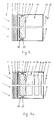
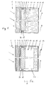
- Fig. 5a and 5b there are presented two types of massive walls 10 with liquid passages.
- the liquid passes through the piping 20 positioned close to the surface 18 of the massive wall 10.
- heat passes to the indoor air 13 and to the other part of massive wall sections 10 which is made of concrete reinforced by steel.
- System shown in Fig. 5a is particularly advantageous for immediate heating of indoor air 13 while another system shown in Fig. 5b is preferred for heating the whole mass of the massive wall 10 with heat release long time after the accumulation period.
- Passages 20 for liquid are there placed in the middle part of the massive wall section 10 while the outside parts are of other construction materials like bricks 21 and/or concrete 22.
- Liquid used in the solar wall according to the present invention is a very important part of the solar wall.
- This liquid is of high heat capacity, low freezing temperature and low viscosity.
- MgC1 2 magnesium chloride
- Solutions of magnesium chloride in water have a heat capacity higher than 3500 KJ/dm3 and provide excellent heat storing properties. Solutions of magnesium chloride are used for massive wall sections with passages for liquid as in Fig. 5, Fig. 5a, Fig. 5b and Fig. 6 as well as for massive walls full of liquid as shown in Fig. 4, Fig. 4a.
- Fig. 6 is a construction of a solar wall similar that those of Figs 4, 4a, 5, 5a and 5b except that passage means 6 and 14 connect the intermediate cavity 5 and massive wall section 10 exteriorly and without passing through the second insulation layer.
- passage means 6 and 14 connect the intermediate cavity 5 and massive wall section 10 exteriorly and without passing through the second insulation layer.
- a pump means can be connected to one of the passage 6 and 14 in case the temperature requirements would necessitate an acceleration of the fluid flow and heat transfer to the massive wall section 10.
- the solar walls being the subject of the present invention are provided in a form of one piece element or in form of few separated pieces of construction joined together to form a wall of any building.
- separate pieces solar walls are sticked together using any available fouling or/and insulation materials as well as steel or plastic construction into which the pieces of solar wall are built in and fastened to it.
Priority Applications (1)
| Application Number | Priority Date | Filing Date | Title |
|---|---|---|---|
| EP90630146A EP0473859A1 (de) | 1990-08-27 | 1990-08-27 | Wand zur Absorption der Ausstrahlung und Verfahren zur Absorption der Ausstrahlung und Übertragung der Wärmeenergie in Solarwänden |
Applications Claiming Priority (1)
| Application Number | Priority Date | Filing Date | Title |
|---|---|---|---|
| EP90630146A EP0473859A1 (de) | 1990-08-27 | 1990-08-27 | Wand zur Absorption der Ausstrahlung und Verfahren zur Absorption der Ausstrahlung und Übertragung der Wärmeenergie in Solarwänden |
Publications (1)
| Publication Number | Publication Date |
|---|---|
| EP0473859A1 true EP0473859A1 (de) | 1992-03-11 |
Family
ID=8205881
Family Applications (1)
| Application Number | Title | Priority Date | Filing Date |
|---|---|---|---|
| EP90630146A Withdrawn EP0473859A1 (de) | 1990-08-27 | 1990-08-27 | Wand zur Absorption der Ausstrahlung und Verfahren zur Absorption der Ausstrahlung und Übertragung der Wärmeenergie in Solarwänden |
Country Status (1)
| Country | Link |
|---|---|
| EP (1) | EP0473859A1 (de) |
Cited By (12)
| Publication number | Priority date | Publication date | Assignee | Title |
|---|---|---|---|---|
| EP0609173A2 (de) * | 1993-01-25 | 1994-08-03 | Ernst Schweizer AG, Metallbau, Zürich | Sonnenkollektor-Modul |
| EP0626545A1 (de) * | 1993-05-28 | 1994-11-30 | Fraunhofer-Gesellschaft Zur Förderung Der Angewandten Forschung E.V. | Vorrichtung zur passiven solaren Beheizung von Gebäuden |
| WO1995010740A1 (de) * | 1993-10-13 | 1995-04-20 | Norsk Hydro A.S. | Aussenwandelement für gebäude, insbesondere paneel im brüstungsbereich einer gebäudewand |
| EP0834710A1 (de) * | 1996-10-06 | 1998-04-08 | Norsk Hydro ASA | Aussenwandaufbau für Gebäude, insbesondere Paneel |
| WO1998057101A1 (en) * | 1997-06-13 | 1998-12-17 | Roestvik Harald N | Solar thermal collector element |
| EP2418436A1 (de) * | 2010-08-12 | 2012-02-15 | WCC Ltd. | Solarheizung |
| EP2522927A3 (de) * | 2011-05-13 | 2013-01-23 | Termo Fluids, S.L. | Thermischer Sonnenkollektor mit transparenter Isolierung |
| ES2431470R1 (es) * | 2011-05-13 | 2013-12-04 | Termo Fluids S L | Captadores solares termicos con aislamiento transparente |
| EP2260247B1 (de) | 2008-02-26 | 2016-06-08 | M=Eco² Cvba | Mehrlagige konstruktion mit rohrsystem |
| FR3037981A1 (fr) * | 2015-06-23 | 2016-12-30 | Commissariat Energie Atomique | Procede de pose d'un parement exterieur sur une facade d'un batiment et batiment correspondant |
| US10288318B2 (en) * | 2018-07-05 | 2019-05-14 | John Howard Luck | Heat transfer device for solar heat |
| US10605488B1 (en) * | 2019-04-01 | 2020-03-31 | John Howard Luck | Heat transfer device for solar heating |
Citations (5)
| Publication number | Priority date | Publication date | Assignee | Title |
|---|---|---|---|---|
| US4137964A (en) * | 1974-04-29 | 1979-02-06 | Massachusetts Institute Of Technology | Controllable heat transmission apparatus |
| US4192290A (en) * | 1978-04-28 | 1980-03-11 | The United States Of America As Represented By The Administrator Of The National Aeronautics And Space Administration | Combined solar collector and energy storage system |
| US4294229A (en) * | 1978-09-12 | 1981-10-13 | One Design, Inc. | Thermosiphoning module for environmentally driven heating and cooling system |
| US4350145A (en) * | 1981-01-30 | 1982-09-21 | Societa Italiana Brevetti | Solar collector for heating purposes |
| FR2575811A1 (fr) * | 1985-01-09 | 1986-07-11 | Total Energie Dev | Ensemble capteur-stockeur pour le chauffage d'eau par energie solaire |
-
1990
- 1990-08-27 EP EP90630146A patent/EP0473859A1/de not_active Withdrawn
Patent Citations (5)
| Publication number | Priority date | Publication date | Assignee | Title |
|---|---|---|---|---|
| US4137964A (en) * | 1974-04-29 | 1979-02-06 | Massachusetts Institute Of Technology | Controllable heat transmission apparatus |
| US4192290A (en) * | 1978-04-28 | 1980-03-11 | The United States Of America As Represented By The Administrator Of The National Aeronautics And Space Administration | Combined solar collector and energy storage system |
| US4294229A (en) * | 1978-09-12 | 1981-10-13 | One Design, Inc. | Thermosiphoning module for environmentally driven heating and cooling system |
| US4350145A (en) * | 1981-01-30 | 1982-09-21 | Societa Italiana Brevetti | Solar collector for heating purposes |
| FR2575811A1 (fr) * | 1985-01-09 | 1986-07-11 | Total Energie Dev | Ensemble capteur-stockeur pour le chauffage d'eau par energie solaire |
Cited By (17)
| Publication number | Priority date | Publication date | Assignee | Title |
|---|---|---|---|---|
| EP0609173A2 (de) * | 1993-01-25 | 1994-08-03 | Ernst Schweizer AG, Metallbau, Zürich | Sonnenkollektor-Modul |
| EP0609173A3 (de) * | 1993-01-25 | 1995-03-29 | Schweizer Ag E | Sonnenkollektor-Modul. |
| EP0626545A1 (de) * | 1993-05-28 | 1994-11-30 | Fraunhofer-Gesellschaft Zur Förderung Der Angewandten Forschung E.V. | Vorrichtung zur passiven solaren Beheizung von Gebäuden |
| WO1995010740A1 (de) * | 1993-10-13 | 1995-04-20 | Norsk Hydro A.S. | Aussenwandelement für gebäude, insbesondere paneel im brüstungsbereich einer gebäudewand |
| WO1995010741A1 (de) * | 1993-10-13 | 1995-04-20 | Norsk Hydro A.S. | Aussenwandaufbau für gebäude, insbesondere paneel im brüstungsbereich einer gebäudewand |
| EP0834710A1 (de) * | 1996-10-06 | 1998-04-08 | Norsk Hydro ASA | Aussenwandaufbau für Gebäude, insbesondere Paneel |
| WO1998015786A1 (de) * | 1996-10-06 | 1998-04-16 | Norsk Hydro Asa | Aussenwandaufbau für gebäude, insbesondere paneel |
| WO1998057101A1 (en) * | 1997-06-13 | 1998-12-17 | Roestvik Harald N | Solar thermal collector element |
| EP2260247B1 (de) | 2008-02-26 | 2016-06-08 | M=Eco² Cvba | Mehrlagige konstruktion mit rohrsystem |
| WO2012020116A1 (en) * | 2010-08-12 | 2012-02-16 | Wcc Ltd. | Solar heater |
| EP2418436A1 (de) * | 2010-08-12 | 2012-02-15 | WCC Ltd. | Solarheizung |
| EP2522927A3 (de) * | 2011-05-13 | 2013-01-23 | Termo Fluids, S.L. | Thermischer Sonnenkollektor mit transparenter Isolierung |
| ES2431470R1 (es) * | 2011-05-13 | 2013-12-04 | Termo Fluids S L | Captadores solares termicos con aislamiento transparente |
| FR3037981A1 (fr) * | 2015-06-23 | 2016-12-30 | Commissariat Energie Atomique | Procede de pose d'un parement exterieur sur une facade d'un batiment et batiment correspondant |
| EP3112773A1 (de) * | 2015-06-23 | 2017-01-04 | Commissariat A L'energie Atomique Et Aux Energies Alternatives | Verfahren zur anbringung einer aussenverkleidung auf einer gebäudefassade, und entsprechendes gebäude |
| US10288318B2 (en) * | 2018-07-05 | 2019-05-14 | John Howard Luck | Heat transfer device for solar heat |
| US10605488B1 (en) * | 2019-04-01 | 2020-03-31 | John Howard Luck | Heat transfer device for solar heating |
Similar Documents
| Publication | Publication Date | Title |
|---|---|---|
| US4411255A (en) | Passive thermal storage wall structures for heating and cooling buildings | |
| US7077124B2 (en) | Wall integrated thermal solar collector with heat storage capacity | |
| US4213448A (en) | Thermosiphon solar space heating system with phase change materials | |
| US3893506A (en) | Device for the absorption and emission of heat | |
| EP0473859A1 (de) | Wand zur Absorption der Ausstrahlung und Verfahren zur Absorption der Ausstrahlung und Übertragung der Wärmeenergie in Solarwänden | |
| US4183350A (en) | Prefabricated outer wall element | |
| US4089142A (en) | Solar-heated concrete slab building structure | |
| US4248291A (en) | Compact thermal energy reservoirs | |
| US4203489A (en) | Thermal energy storage system | |
| US4531511A (en) | Means for controlling heat flux | |
| US3946720A (en) | Solar heat collector | |
| NO300242B1 (no) | Varmeveksleranordning av platetypen | |
| US4596237A (en) | Solar-energy converter | |
| US5070933A (en) | Temperature regulating system | |
| AU2009232081A1 (en) | Novel sustainable building model | |
| US6763826B1 (en) | Solar water heater | |
| GB2103783A (en) | Solar heating | |
| US4149589A (en) | Self-insulating water wall | |
| JPH07166615A (ja) | 省エネルギパネルシステム | |
| FR2570734A1 (fr) | Procedes d'isolation thermique des batiments et batiments realises selon ces procedes | |
| CN213837163U (zh) | 一种增强隔热的蓄水模块围护结构 | |
| JPS629822B2 (de) | ||
| JP2003202130A (ja) | 冷暖房装置 | |
| SU1333995A1 (ru) | Гелиосистема воздушного отоплени здани | |
| JPS5919907Y2 (ja) | 温度成層型蓄熱槽装置 |
Legal Events
| Date | Code | Title | Description |
|---|---|---|---|
| PUAI | Public reference made under article 153(3) epc to a published international application that has entered the european phase |
Free format text: ORIGINAL CODE: 0009012 |
|
| AK | Designated contracting states |
Kind code of ref document: A1 Designated state(s): AT BE CH DE DK ES FR GB GR IT LI LU NL SE |
|
| 17P | Request for examination filed |
Effective date: 19921024 |
|
| 17Q | First examination report despatched |
Effective date: 19930816 |
|
| STAA | Information on the status of an ep patent application or granted ep patent |
Free format text: STATUS: THE APPLICATION IS DEEMED TO BE WITHDRAWN |
|
| 18D | Application deemed to be withdrawn |
Effective date: 19940301 |