EP0473456A2 - A rotary powder compression molding machine - Google Patents
A rotary powder compression molding machine Download PDFInfo
- Publication number
- EP0473456A2 EP0473456A2 EP19910307985 EP91307985A EP0473456A2 EP 0473456 A2 EP0473456 A2 EP 0473456A2 EP 19910307985 EP19910307985 EP 19910307985 EP 91307985 A EP91307985 A EP 91307985A EP 0473456 A2 EP0473456 A2 EP 0473456A2
- Authority
- EP
- European Patent Office
- Prior art keywords
- powder
- turntable
- molding machine
- compression molding
- bore
- Prior art date
- Legal status (The legal status is an assumption and is not a legal conclusion. Google has not performed a legal analysis and makes no representation as to the accuracy of the status listed.)
- Granted
Links
Images

Classifications
-
- B—PERFORMING OPERATIONS; TRANSPORTING
- B30—PRESSES
- B30B—PRESSES IN GENERAL
- B30B15/00—Details of, or accessories for, presses; Auxiliary measures in connection with pressing
- B30B15/30—Feeding material to presses
- B30B15/302—Feeding material in particulate or plastic state to moulding presses
- B30B15/304—Feeding material in particulate or plastic state to moulding presses by using feed frames or shoes with relative movement with regard to the mould or moulds
-
- B—PERFORMING OPERATIONS; TRANSPORTING
- B30—PRESSES
- B30B—PRESSES IN GENERAL
- B30B11/00—Presses specially adapted for forming shaped articles from material in particulate or plastic state, e.g. briquetting presses, tabletting presses
- B30B11/02—Presses specially adapted for forming shaped articles from material in particulate or plastic state, e.g. briquetting presses, tabletting presses using a ram exerting pressure on the material in a moulding space
- B30B11/08—Presses specially adapted for forming shaped articles from material in particulate or plastic state, e.g. briquetting presses, tabletting presses using a ram exerting pressure on the material in a moulding space co-operating with moulds carried by a turntable
Definitions
- the present invention relates to a rotary powder compression molding machine used for producing tablets and the like.
- a rotary powder compression molding machine called a tablet machine has been used for producing medicine, food, bubble bath and the like in a tablet shape.
- the rotary powder compression molding machine comprises a compression molding machine body having a turntable provided with a plurality of bores positioned at a predetermined distance therebetween in the rotation direction, and a powder supply device for supplying powder in each bore of the turntable of the compression molding machine body.
- the powder is successively supplied in each bore of the turntable by the powder supply device while the turntable rotates, and the powder is compressed for molding in each bore by the time when the turntable completes its rotation of one circle, whereby tablets are successively produced.
- a rotary powder compression molding machine in which an open feed shoe is provided in a powder supply device so as to be adjacent to the surface of a turntable of a compression molding machine body has been developed. According to this machine, powder is directly dropped onto the upper surface of the turntable on the upstream side of the open feed shoe in the rotation direction of the turntable.
- Japanese Laid-Open Patent Publication No. 57-50160 discloses a method for regulating the holdup of the powder in the open feed shoe, in which the level and the density of the powder held in the open feed shoe are detected to regulate the amount of the powder so that the holdup of the powder in the open feed shoe is maintained constant.
- the powder supply device is forcibly transferred from one end of the open feed shoe to the other end thereof, and the powder is supplied onto the turntable. Because of this, the holdup of the powder in the open feed shoe is greater than that when the powder is supplied onto the turntable from the hopper, and defective tablets caused by the bridge are not likely to be produced.
- the level and the density of the powder transferred by the open feed shoe are measured, so that it is not possible to prevent the tablets whose weight does not reach a prescribed value from being produced when the powder is not supplied onto the turntable from the open feed shoe.
- a rotary powder compression molding machine comprising: a compression molding machine body having a horizontal turntable provided with a plurality of bores at a distance therebetween in the rotation direction, and means for compressing powder successively filled in each bore on the turntable for molding; a powder supply device having an open feed shoe adjacent to an upper surface of the turntable in the compression molding machine body, and means for dropping powder on an upstream side of the open feed shoe in the rotation direction of the turntable; and a detecting device having an ultrasonic sensor which is disposed so that an ultrasonic wave is reflected from a region of the upper surface of the turntable on which powder is dropped by the means for dropping powder of the powder supply device, and which detects the intensity of the reflected ultrasonic wave.
- the compression molding machine body comprises an upper rod and a lower rod for each bore, which respectively engage an upper part and a lower part of each bore, powder being filled between the upper rod and the lower rod, and which rotate together with the turntable.
- the upper rod and the lower rod move so that powder filled therebetween is pre-loaded by a pre-loading device and pressed by a pressure device.
- the means for dropping powder is a hopper.
- the invention described herein makes possible the objective of providing a rotary powder compression molding machine having a simple construction and high precision, which is capable of detecting the production of defective tablets because of its property of immediately detecting a state in which the powder is not supplied onto the turntable.
- Figure 1 is a vertical cross-sectional view showing main portions of an example of a rotary powder compression molding machine according to the present invention.
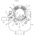
- Figure 2 is a plan view showing a whole construction of the rotary powder compression molding machine.
- Figure 3 is a vertical cross-sectional view illustrating the operation of the rotary powder compression molding machine.
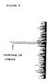
- Figure 4 is a waveform diagram showing the intensity of the ultrasonic sensor.
- a rotary powder compression molding machine of the present invention is, for example, used for the production of tablets of medicine and the like.
- the rotary powder compression molding machine comprises a compression molding machine body 10 having a horizontal turntable 11, a powder supply device for supplying powder 40 onto the turntable 11 , and a detecting device 30 for detecting a shortage of the powder 40 which will be supplied onto the turntable 11 by the powder supply device 20.
- the turntable 11 is, for example, made of a metal plate, and the upper surface thereof is flat without unevenness.
- the turntable 11 has a plurality of bores 11a formed at an equal distance therebetween in the rotation direction end is rotated on a frame 12 in the rotation direction at a predetermined speed. Because of this rotation, the powder 40 supplied onto the turntable 11 from the powder supply device 20 successlvely fills in each bore 11a.
- an upper rod 13 and a lower rod 14 which are rotated together with the turntable 11 are disposed above and below each bore 11a.
- the powder supply device 20 comprises a hopper 21 which directly drops the powder 40 to be compressed for molding onto a predetermined region on the turntable 11 and an open feed shoe 22 for holding the powder 40 dropped onto the turntable 11 by the hogper 21.
- the open feed shoe 22 has a plurality of banks 22a, 22a, ... formed on the turntable 11 at an appropriate distance therebetween in the rotation direction.
- Each bank 22a approaches the upper surface of the turntable 11 in accordance with the rotation of the turntable 11.
- a pre-loading device 15 is positioned at an appropriate distance, further downstream from the bank 22a disposed on the most downstream side in the rotation direction of the turntable 11 of the open feed shoe 22.
- a pressure device 16 is positioned further downstream from the pre-loading device 15 at an appropriate distance.
- the pre-loading device 15 has a pair of pre-loading rollers disposed above and below each bore 11a so as to oppose to each other. Also, the pressure device 16 has a pair of pressure rollers in the same way as in the pre-loading device 15.
- Each upper rod 13 and each lower rod 14 are raised and lowered while being rotated in the rotation direction together with the turntable 11.
- the lower rod 14 On the upstream side from the region to which the hopper 21 opposes in the rotation direction, the lower rod 14 is raised so as to engage each bore 11a to predetermined length, and is rotated in the rotation direction while engaged in each bore 11a.
- the upper rod 13 On the other hand, the upper rod 13 is in a position retracted upward of each bore 11a except for the region where the pre-loading device 15 and the pressure device 16 are disposed and the vicinity thereof.
- the detecting device 30 has an ultrasonic sensor 31 disposed slightly above the slightly upstream region from the position on the turntable 11 where the powder 40 will be dropped.
- the ultrasonic sensor 31 is of a reflection-type, and comprises a transmitting portion for transmitting an ultrasonic wave toward the position on the turntable 11 where the powder 40 will be dropped and a receiving portion for detecting an ultrasonic wave reflected from the upper surface of the turntable 11.
- the intensity of the ultrasonic wave received at the receiving portion of the ultrasonic sensor 31 is displayed in a display monitor 32.
- the ultrasonic wave transmitted from the transmitting portion of the ultrasonic sensor 31 is irregularly reflected from the powder 40 when the powder 40 is present in the position on the turntable 11 where powder will be dropped, so that the ultrasonic wave detected by the receiving portion of the ultrasonic sensor 31 is substantially attenuated.
- the ultrasonic wave is reflected from the upper surface (metal surface) of the turntable 11, so that the receiving portion detects the ultrasonic wave with high intensity. Accordingly, a shortage of the powder 40 in the position where powder 40 will be dropped is immediately detected by observing the reflected wave detected by the ultrasonic sensor 31 by the means of the display monitor 32.
- the turntable 11 of the compression molding machine body 10 is rotated under the condition that the powder 40 is filled in the hopper 21 of the powder supply device 20.
- Each upper rod 13 and each lower rod 14 are rotated in the circumferential direction in accordance with the rotation of the turntable 11.
- Each bore 11a engaged with each lower rod 14 is moved into the region where the powder 40 will be dropped from the hopper 21.
- the powder 40 dropped onto the turntable 11 from the hopper 21 is partially filled in each bore 11a of the turntable 11.
- the powder 40 on the turntable 11 is dammed up by the bank 22a positioned on the most upstream side of the open feed shoe 22 due to the rotation of the turntable 11, the powder 40 is spread over the turntable 11 upstream of this bank 22a and the powder whose level is approximately equal to that of the upper surface of the turntable 11 is filled in the bore 11a .
- the powder 40 on the turntable 11 partially climbs over this bank 22a, and the powder 40 which climbs over this bank 22a is dammed up by the bank 22a disposed downstream the above bank 22a.
- the powder 40 is successively dammed up by each bank 22a so that a predetermined amount of powder which climbs up each bank 22a is filled in each bore 11a.
- each upper rod 13 and each lower rod 14 are pressed by each pre-loading roller of the pre-loading device 15 and each roller of the pressure device 16, and the powder filled in each bore 11a is compressed to form tablets. Accordingly, the tablets formed in each bore 11a are discharged from each bore 11a by the upturn of each lower rod 14 by the time when each bore 11a reaches a region where the powder supply device 20 is disposed, and then the tablets are carried out of the compression molding machine 10 by a shoot 17 disposed downstream the pressure device 16.
- the detecting device 30 detects the powder 40 on the turntable 11 dropped from the hopper.
- Operators observe the intensity of the reflection wave detected by the ultrasonic sensor 31 by means of the display monitor and the machine is adapted to be automatically stopped in case of abnormality.
- the powder 40 is smoothly dropped from the hopper 21 to the position on the turntable 11 where powder will be dropped, the powder 40 is spread into the region where the ultrasonic wave of the ultrasonic sensor 31 is transmitted. Accordingly, the intensity of the ultrasonic wave transmitted by the ultrasonic sensor 31 is low, and all of the bores 11a of the turntable 11 which pass below each bank 22a of the open feed shoe 22 is successively filled with the powder 40.
- the powder 40 forms a bridge in the hopper 21, as shown in Figure 3, the powder 40 is not dropped from the hopper 21 onto the turntable 11 in spite of the fact that the powder 40 is present in the hopper 21. Under this condition, the powder 40 is not present in the region where the ultrasonic wave of the ultrasonic sensor 31 is transmitted, and the ultrasonic wave transmitted from the ultrasonic sensor 31 is reflected from the upper surface of the turntable 11 . Because of this, the intensity of the reflection wave displayed by the display monitor 32 rapidly increases as shown in Figure 4. Accordingly, a state in which the powder 40 is not dropped from the hopper 21 onto the turntable 11 due to the bridge can be immediately detected by observing the reflection wave displayed by the display monitor 32.
- this state can be detected by the intensity of the ultrasonic wave displayed by the display monitor 32.
- the results of the detection by the ultrasonic sensor 31 are displayed by the display monitor 32 .
- the intensity of the ultrasonic wave detected by the ultrasonic sensor 31 becomes higher than a predetermined value, an alarm can be rung.
- the ultrasonic sensor is disposed in the direction of the position on the turntable where the powder will be dropped, so that the state in which the powder is not dropped onto the turntable is immediately detected. Accordingly, even when a predetermined amount of powder is not filled in each bore, tablets whose weight does not reach a prescribed value can be prevented from being produced. Moreover, because of the ultrasonic sensor, the detecting device for detecting the state in which the powder is not dropped can detect the shortage of the powder with high precision and can be readily attached to the compression molding machine body or the powder supply device.
Abstract
Description
- The present invention relates to a rotary powder compression molding machine used for producing tablets and the like.
- A rotary powder compression molding machine called a tablet machine has been used for producing medicine, food, bubble bath and the like in a tablet shape. The rotary powder compression molding machine comprises a compression molding machine body having a turntable provided with a plurality of bores positioned at a predetermined distance therebetween in the rotation direction, and a powder supply device for supplying powder in each bore of the turntable of the compression molding machine body. The powder is successively supplied in each bore of the turntable by the powder supply device while the turntable rotates, and the powder is compressed for molding in each bore by the time when the turntable completes its rotation of one circle, whereby tablets are successively produced.
- A rotary powder compression molding machine in which an open feed shoe is provided in a powder supply device so as to be adjacent to the surface of a turntable of a compression molding machine body has been developed. According to this machine, powder is directly dropped onto the upper surface of the turntable on the upstream side of the open feed shoe in the rotation direction of the turntable.
- In the rotary powder compression molding machine provided with this kind of powder supply device, powder is liable to form a bridge in a hopper of the powder supply device. Under this condition, the supply of the powder onto the turntable is prevented. When the powder is directly dropped onto the surface of the turntable, the holdup of the powder in the open feed shoe is substantially small. When the powder is prevented from being supplied from the hopper to the open feed shoe, the amount of the powder which will be loaded into the bore immediately runs short, resulting in the production of defective tablets whose weight does not reach a prescribed value. Moreover, the bridge formed by the powder in the hopper is merely maintained for a short period of time, and at the next moment after the supply of the powder from the hopper to the open feed shoe is terminated, the powder begins to be supplied again. Therefore, it is very difficult to detect the above abnormality under the supervision of operators and inspectors for the operation processes. Accordingly, when the powder is divided to be put into small packages, the shortage of the weight is found, causing great problems in production processes and quality control of the tablets.
- As a method for preventing the production of these defective tablets whose weight does not reach a prescribed value, a method for detecting a shortage of the powder in the hopper by disposing a powder sensor in the hopper, a method for detecting a shortage of the powder which will be loaded into the bore by using the change of pressure when the powder is compressed for molding in the bore, and the like have been known. However, according to the former method, the defective tablets caused by the temporary interruption of the supply of the powder when the powder forms a bridge in the hopper cannot be prevented. According to the latter method, the apparatus becomes too large to be applied to the existing machine.
- Japanese Laid-Open Patent Publication No. 57-50160 discloses a method for regulating the holdup of the powder in the open feed shoe, in which the level and the density of the powder held in the open feed shoe are detected to regulate the amount of the powder so that the holdup of the powder in the open feed shoe is maintained constant. In this method, the powder supply device is forcibly transferred from one end of the open feed shoe to the other end thereof, and the powder is supplied onto the turntable. Because of this, the holdup of the powder in the open feed shoe is greater than that when the powder is supplied onto the turntable from the hopper, and defective tablets caused by the bridge are not likely to be produced. However, in this method, the level and the density of the powder transferred by the open feed shoe are measured, so that it is not possible to prevent the tablets whose weight does not reach a prescribed value from being produced when the powder is not supplied onto the turntable from the open feed shoe.
- According to the present invention, there is provided a rotary powder compression molding machine, comprising:
a compression molding machine body having a horizontal turntable provided with a plurality of bores at a distance therebetween in the rotation direction, and means for compressing powder successively filled in each bore on the turntable for molding;
a powder supply device having an open feed shoe adjacent to an upper surface of the turntable in the compression molding machine body, and means for dropping powder on an upstream side of the open feed shoe in the rotation direction of the turntable; and
a detecting device having an ultrasonic sensor which is disposed so that an ultrasonic wave is reflected from a region of the upper surface of the turntable on which powder is dropped by the means for dropping powder of the powder supply device, and which detects the intensity of the reflected ultrasonic wave. - In a preferred embodiment, the compression molding machine body comprises an upper rod and a lower rod for each bore, which respectively engage an upper part and a lower part of each bore, powder being filled between the upper rod and the lower rod, and which rotate together with the turntable.
- In a preferred embodiment, the upper rod and the lower rod move so that powder filled therebetween is pre-loaded by a pre-loading device and pressed by a pressure device.
- In a preferred embodiment, the means for dropping powder is a hopper.
- Thus, the invention described herein makes possible the objective of providing a rotary powder compression molding machine having a simple construction and high precision, which is capable of detecting the production of defective tablets because of its property of immediately detecting a state in which the powder is not supplied onto the turntable.
- For a better understanding of the invention and to show how the same may be carried into effect, reference will now be made, by way of example, to the accompanying drawings, wherein:
- Figure 1 is a vertical cross-sectional view showing main portions of an example of a rotary powder compression molding machine according to the present invention.
- Figure 2 is a plan view showing a whole construction of the rotary powder compression molding machine.
- Figure 3 is a vertical cross-sectional view illustrating the operation of the rotary powder compression molding machine.
- Figure 4 is a waveform diagram showing the intensity of the ultrasonic sensor.
- The present invention will be described by way of illustrating an example.
- A rotary powder compression molding machine of the present invention is, for example, used for the production of tablets of medicine and the like. As shown in Figures 1 and 2, the rotary powder compression molding machine comprises a compression
molding machine body 10 having ahorizontal turntable 11, a powder supply device for supplyingpowder 40 onto theturntable 11, and a detectingdevice 30 for detecting a shortage of thepowder 40 which will be supplied onto theturntable 11 by thepowder supply device 20. - The
turntable 11 is, for example, made of a metal plate, and the upper surface thereof is flat without unevenness. Theturntable 11 has a plurality ofbores 11a formed at an equal distance therebetween in the rotation direction end is rotated on aframe 12 in the rotation direction at a predetermined speed. Because of this rotation, thepowder 40 supplied onto theturntable 11 from thepowder supply device 20 successlvely fills in eachbore 11a. - In the compression
molding machine body 10, anupper rod 13 and alower rod 14 which are rotated together with theturntable 11 are disposed above and below eachbore 11a. - The
powder supply device 20 comprises ahopper 21 which directly drops thepowder 40 to be compressed for molding onto a predetermined region on theturntable 11 and anopen feed shoe 22 for holding thepowder 40 dropped onto theturntable 11 by thehogper 21. Theopen feed shoe 22 has a plurality ofbanks turntable 11 at an appropriate distance therebetween in the rotation direction. Eachbank 22a approaches the upper surface of theturntable 11 in accordance with the rotation of theturntable 11. Thehopper 21, which is positioned further upstream from thebank 22a disposed on the most upstream side in the rotation direction, drops thepowder 40 at the periphery of thebores 11a on the upper surface of theturntable 11. - A
pre-loading device 15 is positioned at an appropriate distance, further downstream from thebank 22a disposed on the most downstream side in the rotation direction of theturntable 11 of theopen feed shoe 22. Apressure device 16 is positioned further downstream from thepre-loading device 15 at an appropriate distance. Thepre-loading device 15 has a pair of pre-loading rollers disposed above and below eachbore 11a so as to oppose to each other. Also, thepressure device 16 has a pair of pressure rollers in the same way as in thepre-loading device 15. - Each
upper rod 13 and eachlower rod 14 are raised and lowered while being rotated in the rotation direction together with theturntable 11. On the upstream side from the region to which thehopper 21 opposes in the rotation direction, thelower rod 14 is raised so as to engage eachbore 11a to predetermined length, and is rotated in the rotation direction while engaged in eachbore 11a. On the other hand, theupper rod 13 is in a position retracted upward of eachbore 11a except for the region where thepre-loading device 15 and thepressure device 16 are disposed and the vicinity thereof. - The detecting
device 30 has anultrasonic sensor 31 disposed slightly above the slightly upstream region from the position on theturntable 11 where thepowder 40 will be dropped. Theultrasonic sensor 31 is of a reflection-type, and comprises a transmitting portion for transmitting an ultrasonic wave toward the position on theturntable 11 where thepowder 40 will be dropped and a receiving portion for detecting an ultrasonic wave reflected from the upper surface of theturntable 11. The intensity of the ultrasonic wave received at the receiving portion of theultrasonic sensor 31 is displayed in adisplay monitor 32. The ultrasonic wave transmitted from the transmitting portion of theultrasonic sensor 31 is irregularly reflected from thepowder 40 when thepowder 40 is present in the position on theturntable 11 where powder will be dropped, so that the ultrasonic wave detected by the receiving portion of theultrasonic sensor 31 is substantially attenuated. In contrast, when thepowder 40 is not present in the position where powder will be dropped, the ultrasonic wave is reflected from the upper surface (metal surface) of theturntable 11, so that the receiving portion detects the ultrasonic wave with high intensity. Accordingly, a shortage of thepowder 40 in the position wherepowder 40 will be dropped is immediately detected by observing the reflected wave detected by theultrasonic sensor 31 by the means of thedisplay monitor 32. - In the rotary powder compression molding machine of the present invention having the above-mentioned construction, the
turntable 11 of the compressionmolding machine body 10 is rotated under the condition that thepowder 40 is filled in thehopper 21 of thepowder supply device 20. Eachupper rod 13 and eachlower rod 14 are rotated in the circumferential direction in accordance with the rotation of theturntable 11. Eachbore 11a engaged with eachlower rod 14 is moved into the region where thepowder 40 will be dropped from thehopper 21. Thepowder 40 dropped onto theturntable 11 from thehopper 21 is partially filled in eachbore 11a of theturntable 11. Since thepowder 40 on theturntable 11 is dammed up by thebank 22a positioned on the most upstream side of theopen feed shoe 22 due to the rotation of theturntable 11, thepowder 40 is spread over theturntable 11 upstream of thisbank 22a and the powder whose level is approximately equal to that of the upper surface of theturntable 11 is filled in thebore 11a. Thepowder 40 on theturntable 11 partially climbs over thisbank 22a, and thepowder 40 which climbs over thisbank 22a is dammed up by thebank 22a disposed downstream theabove bank 22a. In the same way, thepowder 40 is successively dammed up by eachbank 22a so that a predetermined amount of powder which climbs up eachbank 22a is filled in eachbore 11a. - In this way, when a predetermined amount of powder is filled in each
bore 11a, eachupper rod 13 and eachlower rod 14 are pressed by each pre-loading roller of thepre-loading device 15 and each roller of thepressure device 16, and the powder filled in eachbore 11a is compressed to form tablets. Accordingly, the tablets formed in eachbore 11a are discharged from eachbore 11a by the upturn of eachlower rod 14 by the time when eachbore 11a reaches a region where thepowder supply device 20 is disposed, and then the tablets are carried out of thecompression molding machine 10 by ashoot 17 disposed downstream thepressure device 16. - In the course of the formation of tablets, the detecting
device 30 detects thepowder 40 on theturntable 11 dropped from the hopper. Operators observe the intensity of the reflection wave detected by theultrasonic sensor 31 by means of the display monitor and the machine is adapted to be automatically stopped in case of abnormality. When thepowder 40 is smoothly dropped from thehopper 21 to the position on theturntable 11 where powder will be dropped, thepowder 40 is spread into the region where the ultrasonic wave of theultrasonic sensor 31 is transmitted. Accordingly, the intensity of the ultrasonic wave transmitted by theultrasonic sensor 31 is low, and all of thebores 11a of theturntable 11 which pass below eachbank 22a of theopen feed shoe 22 is successively filled with thepowder 40. - When the
powder 40 forms a bridge in thehopper 21, as shown in Figure 3, thepowder 40 is not dropped from thehopper 21 onto theturntable 11 in spite of the fact that thepowder 40 is present in thehopper 21. Under this condition, thepowder 40 is not present in the region where the ultrasonic wave of theultrasonic sensor 31 is transmitted, and the ultrasonic wave transmitted from theultrasonic sensor 31 is reflected from the upper surface of theturntable 11. Because of this, the intensity of the reflection wave displayed by the display monitor 32 rapidly increases as shown in Figure 4. Accordingly, a state in which thepowder 40 is not dropped from thehopper 21 onto theturntable 11 due to the bridge can be immediately detected by observing the reflection wave displayed by thedisplay monitor 32. As a result, when the state in which thepowder 40 is not supplied onto theturntable 11 occurs even for a moment, a state in which a predetermined amount ofpowder 40 is not filled in eachbore 11a is readily detected. Therefore, there isno possibility that tablets whose weight does not reach a predetermined value are produced. - In the same way, when the
powder 40 in thehopper 21 is consumed, this state can be detected by the intensity of the ultrasonic wave displayed by thedisplay monitor 32. - In the above example, the results of the detection by the
ultrasonic sensor 31 are displayed by thedisplay monitor 32. For example, when the intensity of the ultrasonic wave detected by theultrasonic sensor 31 becomes higher than a predetermined value, an alarm can be rung. - As described above, in the rotary powder compression molding machine of the present invention, the ultrasonic sensor is disposed in the direction of the position on the turntable where the powder will be dropped, so that the state in which the powder is not dropped onto the turntable is immediately detected. Accordingly, even when a predetermined amount of powder is not filled in each bore, tablets whose weight does not reach a prescribed value can be prevented from being produced. Moreover, because of the ultrasonic sensor, the detecting device for detecting the state in which the powder is not dropped can detect the shortage of the powder with high precision and can be readily attached to the compression molding machine body or the powder supply device.
Claims (4)
- A rotary powder compression molding machine, comprising;
a compression molding machine body having a horizontal turntable provided with a plurality of bores at a distance therebetween in the rotation direction, and means for compressing powder successively filled in each bore on the turntable for molding;
a powder supply device having an open feed shoe adjacent to an upper surface of the turntable in the compression molding machine body, and means for dropping powder on an upstream side of the open feed shoe in the rotation direction of the turntable; and
a detecting device having an ultrasonic sensor which is disposed so that an ultrasonic wave is reflected from a region of the upper surface of the turntable on which powder is dropped by the means for dropping powder of the powder supply device, and which detects the intensity of the reflected ultrasonic wave. - A rotary powder compression molding machine according to claim 1, wherein the compression molding machine body comprises an upper rod and a lower rod for each bore, which respectively engage an upper part and a lower part of each bore, powder being filled between the upper rod and the lower rod, and which rotate together with the turntable.
- A rotary powder compression molding machine according to claim 2, wherein the upper rod and lower rod move so that powder filled therebetween is pre-loaded by a pre-loading device and pressed by a pressure device.
- A rotary powder compression molding machine according to claim 1, 2, or 3, wherein the means for dropping powder is a hopper.
Applications Claiming Priority (2)
| Application Number | Priority Date | Filing Date | Title |
|---|---|---|---|
| JP1990092044U JPH0810472Y2 (en) | 1990-08-31 | 1990-08-31 | Rotary powder compression molding machine |
| JP92044/90 | 1990-08-31 |
Publications (3)
| Publication Number | Publication Date |
|---|---|
| EP0473456A2 true EP0473456A2 (en) | 1992-03-04 |
| EP0473456A3 EP0473456A3 (en) | 1992-06-17 |
| EP0473456B1 EP0473456B1 (en) | 1994-11-09 |
Family
ID=14043522
Family Applications (1)
| Application Number | Title | Priority Date | Filing Date |
|---|---|---|---|
| EP91307985A Expired - Lifetime EP0473456B1 (en) | 1990-08-31 | 1991-08-30 | A rotary powder compression molding machine |
Country Status (7)
| Country | Link |
|---|---|
| US (1) | US5186956A (en) |
| EP (1) | EP0473456B1 (en) |
| JP (1) | JPH0810472Y2 (en) |
| AT (1) | ATE113897T1 (en) |
| DE (1) | DE69105076T2 (en) |
| DK (1) | DK0473456T3 (en) |
| ES (1) | ES2064046T3 (en) |
Families Citing this family (12)
| Publication number | Priority date | Publication date | Assignee | Title |
|---|---|---|---|---|
| US5585113A (en) * | 1994-09-09 | 1996-12-17 | Korsch Pressen Gmbh | Process for quality control in the production of tablets by pressing |
| CA2176412C (en) * | 1995-05-18 | 2008-10-07 | David Henry Wilson | Rotary tabletting press |
| DE19647089A1 (en) * | 1996-11-14 | 1998-05-28 | Bayer Ag | Device for the controlled spraying of powdered lubricants onto punches and dies of tablet presses |
| ITBO20020452A1 (en) * | 2002-07-15 | 2004-01-15 | Ima Spa | COMPRESSING MACHINE |
| ITRE20020058A1 (en) * | 2002-07-19 | 2004-01-19 | Sacmi | SYNTHETIC DOSE FORMING PLANT |
| SE525367C2 (en) | 2002-11-08 | 2005-02-08 | Nilar Int Ab | An electrode and a method for manufacturing an electrode |
| DE102004008321B3 (en) * | 2004-02-20 | 2005-11-17 | Fette Gmbh | Method and device for quality control in the manufacture of tablets |
| WO2008020421A2 (en) * | 2006-08-17 | 2008-02-21 | The Procter & Gamble Company | Compositions comprising calcium citrate malate and methods for making the same |
| JP4167282B2 (en) * | 2006-10-27 | 2008-10-15 | 日精樹脂工業株式会社 | Support device for injection molding machine |
| US9267504B2 (en) | 2010-08-30 | 2016-02-23 | Hicor Technologies, Inc. | Compressor with liquid injection cooling |
| CA2809945C (en) | 2010-08-30 | 2018-10-16 | Oscomp Systems Inc. | Compressor with liquid injection cooling |
| CN111716809B (en) * | 2020-07-06 | 2022-06-24 | 台州科技职业学院 | Oil press |
Citations (6)
| Publication number | Priority date | Publication date | Assignee | Title |
|---|---|---|---|---|
| US3460487A (en) * | 1967-09-22 | 1969-08-12 | Sterling Drug Inc | Tablet forming machines |
| DE2359474B1 (en) * | 1973-11-29 | 1975-03-20 | Kilian & Co Gmbh, 5000 Koeln | Rotary tablet press |
| JPS5476404A (en) * | 1977-11-30 | 1979-06-19 | Nec Corp | Press molding apparatus for powder |
| JPS6125559A (en) * | 1984-07-13 | 1986-02-04 | 株式会社 菊水製作所 | Nucleus tablet detector of rotary type nucleus provided tablet pressing machine |
| JPS6154435A (en) * | 1984-08-24 | 1986-03-18 | Kikusui Seisakusho:Kk | Detection of nucleated tablet position of rotary nucleated tablet making machine |
| DE3723651A1 (en) * | 1987-07-17 | 1987-12-23 | Blauer Miklos Zoltan Dipl Masc | Universal automatic tablet machine for converting compressed powder into tablets |
Family Cites Families (9)
| Publication number | Priority date | Publication date | Assignee | Title |
|---|---|---|---|---|
| DD78183A (en) * | ||||
| DE2243751A1 (en) * | 1972-09-06 | 1974-03-28 | Berstorff Gmbh Masch Hermann | DEVICE FOR CONTROLLING THE BEAD HEIGHT IN THE ROLL GAP OF A CALENDAR AND THE LIKE TO WHICH THE MATERIAL IS FEEDED FROM A PRE-PLASTICIZING MACHINE, FOR EXAMPLE AN EXTRUDER, ROLLING MILL AND THE LIKE |
| US3836299A (en) * | 1973-08-13 | 1974-09-17 | Fmc Corp | Press for forming one-piece tablet containing seeds or the like |
| US3910739A (en) * | 1973-12-21 | 1975-10-07 | Nikolai Semenovich Talis | Feeding device for a rotary tablet machine |
| US4157148A (en) * | 1977-07-11 | 1979-06-05 | The Upjohn Company | Modified feed frames for tableting machine |
| JPS5750160A (en) * | 1980-09-09 | 1982-03-24 | Fujitsu Ltd | External monitoring system |
| JPS6043840A (en) * | 1983-08-22 | 1985-03-08 | Hitachi Ltd | Semiconductor integrated circuit device |
| JPS60217120A (en) * | 1984-04-13 | 1985-10-30 | Bridgestone Corp | Measuring device for rubber bank amount between rolls |
| US5032071A (en) * | 1990-03-01 | 1991-07-16 | Nabisco Brands, Inc. | Material sensing assembly in a rotary press |
-
1990
- 1990-08-31 JP JP1990092044U patent/JPH0810472Y2/en not_active Expired - Lifetime
-
1991
- 1991-08-30 DE DE69105076T patent/DE69105076T2/en not_active Expired - Fee Related
- 1991-08-30 ES ES91307985T patent/ES2064046T3/en not_active Expired - Lifetime
- 1991-08-30 EP EP91307985A patent/EP0473456B1/en not_active Expired - Lifetime
- 1991-08-30 AT AT91307985T patent/ATE113897T1/en not_active IP Right Cessation
- 1991-08-30 US US07/753,629 patent/US5186956A/en not_active Expired - Fee Related
- 1991-08-30 DK DK91307985.1T patent/DK0473456T3/en active
Patent Citations (6)
| Publication number | Priority date | Publication date | Assignee | Title |
|---|---|---|---|---|
| US3460487A (en) * | 1967-09-22 | 1969-08-12 | Sterling Drug Inc | Tablet forming machines |
| DE2359474B1 (en) * | 1973-11-29 | 1975-03-20 | Kilian & Co Gmbh, 5000 Koeln | Rotary tablet press |
| JPS5476404A (en) * | 1977-11-30 | 1979-06-19 | Nec Corp | Press molding apparatus for powder |
| JPS6125559A (en) * | 1984-07-13 | 1986-02-04 | 株式会社 菊水製作所 | Nucleus tablet detector of rotary type nucleus provided tablet pressing machine |
| JPS6154435A (en) * | 1984-08-24 | 1986-03-18 | Kikusui Seisakusho:Kk | Detection of nucleated tablet position of rotary nucleated tablet making machine |
| DE3723651A1 (en) * | 1987-07-17 | 1987-12-23 | Blauer Miklos Zoltan Dipl Masc | Universal automatic tablet machine for converting compressed powder into tablets |
Non-Patent Citations (3)
| Title |
|---|
| DATABASE WPIL, accession no. 86-073796 [11], Derwent Publications Ltd, London, GB; & JP-A-61 025 559 (KIKUSUI SEISAKUSHO) 04-02-1986 * |
| DATABASE WPIL, accession no. 86-110885 [17], Derwent Publications Ltd, London, GB; & JP-A-61 054 435 (KIKUSUI SEISAKUSHO) 18-03-1986 * |
| PATENT ABSTRACTS OF JAPAN, vol. 3, no. 95 (C-55), 11th August 1979; & JP-A-54 076 404 (NIPPON DENKI K.K.) 19-06-1979 * |
Also Published As
| Publication number | Publication date |
|---|---|
| DE69105076D1 (en) | 1994-12-15 |
| ES2064046T3 (en) | 1995-01-16 |
| JPH0810472Y2 (en) | 1996-03-29 |
| DK0473456T3 (en) | 1994-12-05 |
| EP0473456A3 (en) | 1992-06-17 |
| ATE113897T1 (en) | 1994-11-15 |
| DE69105076T2 (en) | 1995-03-09 |
| EP0473456B1 (en) | 1994-11-09 |
| US5186956A (en) | 1993-02-16 |
| JPH0447895U (en) | 1992-04-23 |
Similar Documents
| Publication | Publication Date | Title |
|---|---|---|
| EP0473456B1 (en) | A rotary powder compression molding machine | |
| US7981352B2 (en) | Method and apparatus for quality surveillance during the manufacture of tablets | |
| US5753866A (en) | Combinational weigher | |
| US8146331B2 (en) | Automated packaging, inspection, verification, and counting apparatus | |
| US5363968A (en) | Automatic blister inspection system | |
| AU594369B2 (en) | Process for adjusting the width of the gap in a cone-type crusher or similar | |
| US11207859B2 (en) | Powdery-material feeding device and powdery-material feeding method | |
| US4756184A (en) | Apparatus and method for seal testing flexible containers | |
| US5575040A (en) | Apparatus for controlling sliver deposition in a coiler can | |
| DE3936163A1 (en) | Measuring soundness of hermetically sealed containers - subjecting flexible part to pressure in test chamber and comparing deformation arising from internal pressure | |
| EP0509809A2 (en) | Crusher roll wear monitoring apparatus and method | |
| EP0706868A1 (en) | Method and device for the quality control of moulded articles | |
| JPS6158140B2 (en) | ||
| US5753585A (en) | Method of packing catalyst | |
| CN209866693U (en) | Fire extinguisher weight on-line measuring device | |
| CA1049448A (en) | Method and apparatus for detecting flaws in circular tablet | |
| CN208933790U (en) | A kind of supply system of gathering materials of continuous asphalt mixing plant | |
| JP2011209156A (en) | Combination weighing device | |
| JPS6160298A (en) | Automatic controller for suppling position of tablet having core of rotary tablet machine | |
| WO1989007083A1 (en) | Tablet alignment apparatus | |
| DE3032934C2 (en) | ||
| JPH0346239B2 (en) | ||
| JPS5922957Y2 (en) | Rotary powder compression molding machine | |
| KR20110084687A (en) | Tablet molding apparatus | |
| US5753273A (en) | System for monitoring and controlling the material composition and plastic or ductile deformation of the mass flow in a machine |
Legal Events
| Date | Code | Title | Description |
|---|---|---|---|
| PUAI | Public reference made under article 153(3) epc to a published international application that has entered the european phase |
Free format text: ORIGINAL CODE: 0009012 |
|
| AK | Designated contracting states |
Kind code of ref document: A2 Designated state(s): AT BE CH DE DK ES FR GB GR IT LI LU NL SE |
|
| PUAL | Search report despatched |
Free format text: ORIGINAL CODE: 0009013 |
|
| AK | Designated contracting states |
Kind code of ref document: A3 Designated state(s): AT BE CH DE DK ES FR GB GR IT LI LU NL SE |
|
| 17P | Request for examination filed |
Effective date: 19920901 |
|
| 17Q | First examination report despatched |
Effective date: 19931206 |
|
| RAP3 | Party data changed (applicant data changed or rights of an application transferred) |
Owner name: SHIONOGI SEIYAKU KABUSHIKI KAISHA TRADING UNDER TH |
|
| GRAA | (expected) grant |
Free format text: ORIGINAL CODE: 0009210 |
|
| AK | Designated contracting states |
Kind code of ref document: B1 Designated state(s): AT BE CH DE DK ES FR GB GR IT LI LU NL SE |
|
| REF | Corresponds to: |
Ref document number: 113897 Country of ref document: AT Date of ref document: 19941115 Kind code of ref document: T |
|
| ITF | It: translation for a ep patent filed |
Owner name: BUGNION S.P.A. |
|
| REG | Reference to a national code |
Ref country code: DK Ref legal event code: T3 |
|
| REF | Corresponds to: |
Ref document number: 69105076 Country of ref document: DE Date of ref document: 19941215 |
|
| ET | Fr: translation filed | ||
| REG | Reference to a national code |
Ref country code: ES Ref legal event code: FG2A Ref document number: 2064046 Country of ref document: ES Kind code of ref document: T3 |
|
| REG | Reference to a national code |
Ref country code: GR Ref legal event code: FG4A Free format text: 3014054 |
|
| PLBE | No opposition filed within time limit |
Free format text: ORIGINAL CODE: 0009261 |
|
| STAA | Information on the status of an ep patent application or granted ep patent |
Free format text: STATUS: NO OPPOSITION FILED WITHIN TIME LIMIT |
|
| 26N | No opposition filed | ||
| REG | Reference to a national code |
Ref country code: GB Ref legal event code: IF02 |
|
| PGFP | Annual fee paid to national office [announced via postgrant information from national office to epo] |
Ref country code: GB Payment date: 20030730 Year of fee payment: 13 |
|
| PGFP | Annual fee paid to national office [announced via postgrant information from national office to epo] |
Ref country code: NL Payment date: 20030731 Year of fee payment: 13 Ref country code: FR Payment date: 20030731 Year of fee payment: 13 Ref country code: CH Payment date: 20030731 Year of fee payment: 13 |
|
| PGFP | Annual fee paid to national office [announced via postgrant information from national office to epo] |
Ref country code: SE Payment date: 20030801 Year of fee payment: 13 |
|
| PGFP | Annual fee paid to national office [announced via postgrant information from national office to epo] |
Ref country code: DK Payment date: 20030805 Year of fee payment: 13 |
|
| PGFP | Annual fee paid to national office [announced via postgrant information from national office to epo] |
Ref country code: GR Payment date: 20030806 Year of fee payment: 13 |
|
| PGFP | Annual fee paid to national office [announced via postgrant information from national office to epo] |
Ref country code: LU Payment date: 20030811 Year of fee payment: 13 |
|
| PGFP | Annual fee paid to national office [announced via postgrant information from national office to epo] |
Ref country code: ES Payment date: 20030818 Year of fee payment: 13 Ref country code: BE Payment date: 20030818 Year of fee payment: 13 |
|
| PGFP | Annual fee paid to national office [announced via postgrant information from national office to epo] |
Ref country code: AT Payment date: 20030826 Year of fee payment: 13 |
|
| PGFP | Annual fee paid to national office [announced via postgrant information from national office to epo] |
Ref country code: DE Payment date: 20030828 Year of fee payment: 13 |
|
| PG25 | Lapsed in a contracting state [announced via postgrant information from national office to epo] |
Ref country code: LU Free format text: LAPSE BECAUSE OF NON-PAYMENT OF DUE FEES Effective date: 20040830 Ref country code: GB Free format text: LAPSE BECAUSE OF NON-PAYMENT OF DUE FEES Effective date: 20040830 Ref country code: AT Free format text: LAPSE BECAUSE OF NON-PAYMENT OF DUE FEES Effective date: 20040830 |
|
| PG25 | Lapsed in a contracting state [announced via postgrant information from national office to epo] |
Ref country code: SE Free format text: LAPSE BECAUSE OF NON-PAYMENT OF DUE FEES Effective date: 20040831 Ref country code: LI Free format text: LAPSE BECAUSE OF NON-PAYMENT OF DUE FEES Effective date: 20040831 Ref country code: ES Free format text: LAPSE BECAUSE OF NON-PAYMENT OF DUE FEES Effective date: 20040831 Ref country code: DK Free format text: LAPSE BECAUSE OF NON-PAYMENT OF DUE FEES Effective date: 20040831 Ref country code: CH Free format text: LAPSE BECAUSE OF NON-PAYMENT OF DUE FEES Effective date: 20040831 Ref country code: BE Free format text: LAPSE BECAUSE OF NON-PAYMENT OF DUE FEES Effective date: 20040831 |
|
| BERE | Be: lapsed |
Owner name: *SHIONOGI SEIYAKU K.K. TRADING UNDER THE NAME OF S Effective date: 20040831 |
|
| PG25 | Lapsed in a contracting state [announced via postgrant information from national office to epo] |
Ref country code: NL Free format text: LAPSE BECAUSE OF NON-PAYMENT OF DUE FEES Effective date: 20050301 Ref country code: DE Free format text: LAPSE BECAUSE OF NON-PAYMENT OF DUE FEES Effective date: 20050301 |
|
| PG25 | Lapsed in a contracting state [announced via postgrant information from national office to epo] |
Ref country code: GR Free format text: LAPSE BECAUSE OF NON-PAYMENT OF DUE FEES Effective date: 20050303 |
|
| EUG | Se: european patent has lapsed | ||
| REG | Reference to a national code |
Ref country code: CH Ref legal event code: PL |
|
| GBPC | Gb: european patent ceased through non-payment of renewal fee |
Effective date: 20040830 |
|
| PG25 | Lapsed in a contracting state [announced via postgrant information from national office to epo] |
Ref country code: FR Free format text: LAPSE BECAUSE OF NON-PAYMENT OF DUE FEES Effective date: 20050429 |
|
| NLV4 | Nl: lapsed or anulled due to non-payment of the annual fee |
Effective date: 20050301 |
|
| REG | Reference to a national code |
Ref country code: FR Ref legal event code: ST |
|
| REG | Reference to a national code |
Ref country code: DK Ref legal event code: EBP |
|
| PG25 | Lapsed in a contracting state [announced via postgrant information from national office to epo] |
Ref country code: IT Free format text: LAPSE BECAUSE OF NON-PAYMENT OF DUE FEES;WARNING: LAPSES OF ITALIAN PATENTS WITH EFFECTIVE DATE BEFORE 2007 MAY HAVE OCCURRED AT ANY TIME BEFORE 2007. THE CORRECT EFFECTIVE DATE MAY BE DIFFERENT FROM THE ONE RECORDED. Effective date: 20050830 |
|
| REG | Reference to a national code |
Ref country code: ES Ref legal event code: FD2A Effective date: 20040831 |
|
| BERE | Be: lapsed |
Owner name: *SHIONOGI SEIYAKU K.K. TRADING UNDER THE NAME OF S Effective date: 20040831 |