EP0473357B1 - Module frames - Google Patents
Module frames Download PDFInfo
- Publication number
- EP0473357B1 EP0473357B1 EP91307707A EP91307707A EP0473357B1 EP 0473357 B1 EP0473357 B1 EP 0473357B1 EP 91307707 A EP91307707 A EP 91307707A EP 91307707 A EP91307707 A EP 91307707A EP 0473357 B1 EP0473357 B1 EP 0473357B1
- Authority
- EP
- European Patent Office
- Prior art keywords
- connectors
- module frame
- frame
- module
- connector
- Prior art date
- Legal status (The legal status is an assumption and is not a legal conclusion. Google has not performed a legal analysis and makes no representation as to the accuracy of the status listed.)
- Expired - Lifetime
Links
- 238000000034 method Methods 0.000 claims description 23
- 238000003466 welding Methods 0.000 claims description 18
- 238000009434 installation Methods 0.000 description 6
- 230000000712 assembly Effects 0.000 description 4
- 238000000429 assembly Methods 0.000 description 4
- 230000002787 reinforcement Effects 0.000 description 4
- 230000000694 effects Effects 0.000 description 3
- 238000004519 manufacturing process Methods 0.000 description 3
- 230000008878 coupling Effects 0.000 description 2
- 238000010168 coupling process Methods 0.000 description 2
- 238000005859 coupling reaction Methods 0.000 description 2
- 239000002131 composite material Substances 0.000 description 1
- 238000005520 cutting process Methods 0.000 description 1
- 230000007613 environmental effect Effects 0.000 description 1
- 239000000463 material Substances 0.000 description 1
- 239000002184 metal Substances 0.000 description 1
- 230000010355 oscillation Effects 0.000 description 1
- 230000000452 restraining effect Effects 0.000 description 1
- 239000000725 suspension Substances 0.000 description 1
Images








Classifications
-
- B—PERFORMING OPERATIONS; TRANSPORTING
- B63—SHIPS OR OTHER WATERBORNE VESSELS; RELATED EQUIPMENT
- B63B—SHIPS OR OTHER WATERBORNE VESSELS; EQUIPMENT FOR SHIPPING
- B63B73/00—Building or assembling vessels or marine structures, e.g. hulls or offshore platforms
- B63B73/20—Building or assembling prefabricated vessel modules or parts other than hull blocks, e.g. engine rooms, rudders, propellers, superstructures, berths, holds or tanks
-
- B—PERFORMING OPERATIONS; TRANSPORTING
- B63—SHIPS OR OTHER WATERBORNE VESSELS; RELATED EQUIPMENT
- B63H—MARINE PROPULSION OR STEERING
- B63H21/00—Use of propulsion power plant or units on vessels
- B63H21/30—Mounting of propulsion plant or unit, e.g. for anti-vibration purposes
-
- B—PERFORMING OPERATIONS; TRANSPORTING
- B63—SHIPS OR OTHER WATERBORNE VESSELS; RELATED EQUIPMENT
- B63B—SHIPS OR OTHER WATERBORNE VESSELS; EQUIPMENT FOR SHIPPING
- B63B3/00—Hulls characterised by their structure or component parts
-
- B—PERFORMING OPERATIONS; TRANSPORTING
- B63—SHIPS OR OTHER WATERBORNE VESSELS; RELATED EQUIPMENT
- B63B—SHIPS OR OTHER WATERBORNE VESSELS; EQUIPMENT FOR SHIPPING
- B63B3/00—Hulls characterised by their structure or component parts
- B63B3/14—Hull parts
- B63B3/26—Frames
-
- B—PERFORMING OPERATIONS; TRANSPORTING
- B63—SHIPS OR OTHER WATERBORNE VESSELS; RELATED EQUIPMENT
- B63B—SHIPS OR OTHER WATERBORNE VESSELS; EQUIPMENT FOR SHIPPING
- B63B3/00—Hulls characterised by their structure or component parts
- B63B3/14—Hull parts
- B63B3/26—Frames
- B63B3/32—Web frames; Web beams
-
- B—PERFORMING OPERATIONS; TRANSPORTING
- B63—SHIPS OR OTHER WATERBORNE VESSELS; RELATED EQUIPMENT
- B63B—SHIPS OR OTHER WATERBORNE VESSELS; EQUIPMENT FOR SHIPPING
- B63B73/00—Building or assembling vessels or marine structures, e.g. hulls or offshore platforms
- B63B73/40—Building or assembling vessels or marine structures, e.g. hulls or offshore platforms characterised by joining methods
- B63B73/43—Welding, e.g. laser welding
-
- B—PERFORMING OPERATIONS; TRANSPORTING
- B63—SHIPS OR OTHER WATERBORNE VESSELS; RELATED EQUIPMENT
- B63B—SHIPS OR OTHER WATERBORNE VESSELS; EQUIPMENT FOR SHIPPING
- B63B73/00—Building or assembling vessels or marine structures, e.g. hulls or offshore platforms
- B63B73/60—Building or assembling vessels or marine structures, e.g. hulls or offshore platforms characterised by the use of specific tools or equipment; characterised by automation, e.g. use of robots
-
- E—FIXED CONSTRUCTIONS
- E04—BUILDING
- E04B—GENERAL BUILDING CONSTRUCTIONS; WALLS, e.g. PARTITIONS; ROOFS; FLOORS; CEILINGS; INSULATION OR OTHER PROTECTION OF BUILDINGS
- E04B1/00—Constructions in general; Structures which are not restricted either to walls, e.g. partitions, or floors or ceilings or roofs
- E04B1/38—Connections for building structures in general
- E04B1/388—Separate connecting elements
-
- F—MECHANICAL ENGINEERING; LIGHTING; HEATING; WEAPONS; BLASTING
- F16—ENGINEERING ELEMENTS AND UNITS; GENERAL MEASURES FOR PRODUCING AND MAINTAINING EFFECTIVE FUNCTIONING OF MACHINES OR INSTALLATIONS; THERMAL INSULATION IN GENERAL
- F16B—DEVICES FOR FASTENING OR SECURING CONSTRUCTIONAL ELEMENTS OR MACHINE PARTS TOGETHER, e.g. NAILS, BOLTS, CIRCLIPS, CLAMPS, CLIPS OR WEDGES; JOINTS OR JOINTING
- F16B1/00—Devices for securing together, or preventing relative movement between, constructional elements or machine parts
-
- E—FIXED CONSTRUCTIONS
- E04—BUILDING
- E04B—GENERAL BUILDING CONSTRUCTIONS; WALLS, e.g. PARTITIONS; ROOFS; FLOORS; CEILINGS; INSULATION OR OTHER PROTECTION OF BUILDINGS
- E04B1/00—Constructions in general; Structures which are not restricted either to walls, e.g. partitions, or floors or ceilings or roofs
- E04B1/38—Connections for building structures in general
- E04B1/388—Separate connecting elements
- E04B2001/389—Brackets
-
- Y—GENERAL TAGGING OF NEW TECHNOLOGICAL DEVELOPMENTS; GENERAL TAGGING OF CROSS-SECTIONAL TECHNOLOGIES SPANNING OVER SEVERAL SECTIONS OF THE IPC; TECHNICAL SUBJECTS COVERED BY FORMER USPC CROSS-REFERENCE ART COLLECTIONS [XRACs] AND DIGESTS
- Y10—TECHNICAL SUBJECTS COVERED BY FORMER USPC
- Y10T—TECHNICAL SUBJECTS COVERED BY FORMER US CLASSIFICATION
- Y10T29/00—Metal working
- Y10T29/49—Method of mechanical manufacture
- Y10T29/49616—Structural member making
- Y10T29/49623—Static structure, e.g., a building component
- Y10T29/49625—Openwork, e.g., a truss, joist, frame, lattice-type or box beam
-
- Y—GENERAL TAGGING OF NEW TECHNOLOGICAL DEVELOPMENTS; GENERAL TAGGING OF CROSS-SECTIONAL TECHNOLOGIES SPANNING OVER SEVERAL SECTIONS OF THE IPC; TECHNICAL SUBJECTS COVERED BY FORMER USPC CROSS-REFERENCE ART COLLECTIONS [XRACs] AND DIGESTS
- Y10—TECHNICAL SUBJECTS COVERED BY FORMER USPC
- Y10T—TECHNICAL SUBJECTS COVERED BY FORMER US CLASSIFICATION
- Y10T29/00—Metal working
- Y10T29/49—Method of mechanical manufacture
- Y10T29/49826—Assembling or joining
- Y10T29/49892—Joining plate edge perpendicularly to frame
-
- Y—GENERAL TAGGING OF NEW TECHNOLOGICAL DEVELOPMENTS; GENERAL TAGGING OF CROSS-SECTIONAL TECHNOLOGIES SPANNING OVER SEVERAL SECTIONS OF THE IPC; TECHNICAL SUBJECTS COVERED BY FORMER USPC CROSS-REFERENCE ART COLLECTIONS [XRACs] AND DIGESTS
- Y10—TECHNICAL SUBJECTS COVERED BY FORMER USPC
- Y10T—TECHNICAL SUBJECTS COVERED BY FORMER US CLASSIFICATION
- Y10T29/00—Metal working
- Y10T29/49—Method of mechanical manufacture
- Y10T29/49826—Assembling or joining
- Y10T29/49947—Assembling or joining by applying separate fastener
- Y10T29/49963—Threaded fastener
-
- Y—GENERAL TAGGING OF NEW TECHNOLOGICAL DEVELOPMENTS; GENERAL TAGGING OF CROSS-SECTIONAL TECHNOLOGIES SPANNING OVER SEVERAL SECTIONS OF THE IPC; TECHNICAL SUBJECTS COVERED BY FORMER USPC CROSS-REFERENCE ART COLLECTIONS [XRACs] AND DIGESTS
- Y10—TECHNICAL SUBJECTS COVERED BY FORMER USPC
- Y10T—TECHNICAL SUBJECTS COVERED BY FORMER US CLASSIFICATION
- Y10T403/00—Joints and connections
- Y10T403/50—Bridged by diverse connector
Definitions
- the present invention relates to a method of assembling a module frame adapted to form part of a larger structure, such as an engine room of a large ship, on which fittings are mounted, and to a modular structure comprising a plurality of such module frames connected together.
- An engine room of a ship has a wide variety of fittings, such as machinery, piping and wiring installed in and fixed to the hull.
- fittings such as machinery, piping and wiring installed in and fixed to the hull.
- the deck of the hull is built and then fittings are brought onto or below the deck or into the hull for their installation and fixing on or below the deck.
- the fittings be divided into a plurality of blocks which are mounted on a module frame or frames in a factory.
- the blocks are then moved into the ship together with the module frame(s) for installation.
- One or more further module frames with other fittings are then moved into position and connected to the module frame(s) already in position and the fittings carried by them are also connected together, as appropriate.
- This proposed method would drastically reduce the onboard operations and shorten the period required for installation and fixing since only the module frames manufactured on shore with fittings mounted thereon need to be brought onboard and connected together.
- module frames are very large and are assembled rigidly by welding or the like to enable them to support heavy loads or objects so that it is very difficult to maintain the dimensional accuracy of the module frames against dimensional errors of materials or welding distortion. If the dimensional accuracy is not maintained, an extra operation is required to adjust the module frames and/or fittings with respect to one another in the course of installation in the ship. Such adjustment requires much time and labour and hinders improvement of working efficiency.
- GB-A-2161773 discloses a propulsion module which is housed in a box frame which is connected via connections to a ship's hull or deck.
- the connections include connector brackets attached to the box frame which are connected to mountings connected to the ship. Misalignment of the engine with the propellor shaft is compensated for by an axial radial compensation joint.
- US-A-4682765 discloses a welding jig for use in the manufacture of a metal grating.
- the jig comprises a rectangular frame which is traversed by two spaced parallel support bars, each of which carries a plurality of pivotally mounted cams.
- Each cam is connected to be rotated by a respective bar and all the bars associated with each of the support bars are pivotally connected to a respective common drive bar which is arranged to be moved longitudinally by a respective actuator.
- grating bars are positioned on the jig adjacent the cams and the actuators operated to move the grating bars into predetermined positions relative to one another. End bars are then welded to the ends of the grating bars.
- a method of assembling a module frame for assembly as part of a larger structure with a generally flat shape comprising a pair of horizontal and parallel main beams, a pair of beam members connected to and extending between the main beams and a connector connected to at least one end of each main beam and/or each beam member, the method comprising supporting the components of the module frame, whilst welded together, on a support device in a predetermined position, retaining two or more connectors on respective connector support brackets forming part of the support device, positioning the connector support brackets so that they are in predetermined positions with respect to one another adjacent respective ends of the said components and welding the connectors to the said ends.
- a method of assembling a module frame for assembly as part of a larger structure of three-dimensional shape on which fittings are to be mounted comprising a pair of horizontal and parallel main beams, a pair of beam members connected to and extending between the main beams, a support column extending vertically from each junction of the main beams with the beam members and a connector connected to at least one end of each main beam and/or each beam member and/or each support column, the method comprising supporting the components of the module frame, whilst welded together, on a support device in a predetermined position, retaining two or more connectors on respective connector support brackets forming part of the support device, positioning the connector support brackets so that they are in predetermined positions with respect to one another adjacent respective ends of the said components and welding the connectors to the said ends.
- a method of assembling a module frame for assembly as part of a larger structure of three-dimensional shape on which fittings are to be mounted comprising a horizontal and substantially rectangular floor member, a support column extending vertically from each corner of the floor member and a connector connected to at least one end of each support column, the method comprising supporting the components of the module frame, whilst welded together, on a support device in a predetermined position, retaining two or more connectors on respective connector support brackets forming part of the support device, positioning the connector support brackets so that they are in predetermined positions with respect to one another adjacent respective ends of the support columns and welding the connectors to the said ends.
- the module frames manufactured by the method of the present invention include at least two connectors and preferably include a connector on the or each free end of each main beam, each beam member and, if present, each support column.
- the position of the connectors is precisely fixed with respect to the remainder of the module frame and with respect to predetermined spatial coordinates defined by an assembly device and subsequently connected to the remainder of the module frame.
- Two or more module frames may then be connected together by means of their connectors and fittings carried by them will then automatically be in a precisely predetermined spatial relationship due to the precise prepositioning of the connectors.
- main beams and beam members and support columns or the floor member and support columns are likely to be welded together as a first step and the connector or connectors then welded to the module frame subsequently.
- each free end of each main beam, each beam member and each support column may have a connector connected to it. Whilst this will be the case in connection with a module frame which is to be in the middle of the assembled larger modular structure, it will not necessarily be the case in connection with a module frame which is to be at the outer edge of the final modular structure. However, at this outer edge the modular structure will need to be connected to the larger structure in which it is to be accommodated, such as a ship's engine room, and for this purpose a coupler is required.
- This coupler may comprise two elbow plates connected to the frame module and the larger structure, respectively, and two further plates connected to opposite sides of the elbow plates by bolts which pass through holes, at least some of which may be in the form of elongate slots to permit some positional adjustment to be effected.
- Figs. 1 and 2 show a typical basic form of module frame 1 manufactured according to the present invention which comprises a pair of horizontal, parallel main beams 2, a pair of horizontal, parallel beam members 3 extending perpendicular to and between the main beams 2 and rigidly welded at their opposite ends to the main beams 2 and four support columns 6 each having upper and lower column portions 4 and 5 rigidly welded to and extending vertically from a respective junction of the main beams 2 with the beam members 3.
- a flanged connector 7 is rigidly welded in position at a predetermined position, the connector-mounting position, or on each end of each column 6 and main beam 2.
- reference numeral 8 represents an auxiliary beam added to support fittings such as heavy machinery 9; 3, extensions for connecting the module frame 1 to a stationary member of a hull structure, such as a bulkhead, when the module frame 1 is installed in a ship; 45, reinforcement ribs; and 46, reinforcement brackets.
- the module frame 1 is assembled so that its width, length and height concur with a high accuracy with the size of a hexahedral container shown in phantom lines.
- the module frame 1 has fittings, such as piping 10 and wiring 11, mounted on it.
- the module frame 1 may be assembled with the aid of the device 12 shown in Figs. 3 to 9.
- a pair of parallel, longitudinal frames 13 having the same spacing as that of the main beams 2 of the module frame 1 and longer than the beams 2 are connected to a pair of lateral frames 14 extending perpendicular to the longitudinal frames 13 and having the same spacing as that of the beam members 3 of the module frame 1.
- Fixed side positioning means 15 are mounted on one end of each longitudinal frame 13 to position the main beams 2 in the longitudinal, lateral and vertical directions and moving side positioning means 16 are mounted on the other ends of the frames 13.
- Beam supports 17 are mounted on the upper surfaces of the lateral frames 14 between the longitudinal frames 13 and have the same height as that of the lower column portions 5 of the module frame 1.
- An upper positioning bases 18 having substantially the same height as that of the upper column portions 4 of the module frame 1 are fixed at each end of the lateral frames 14.
- the moving side positioning means 16 comprises a movable base 22 which is movable by liner rollers 20 or the like along the length of the longitudinal frames 13 and which has a connector support bracket 21 thereon for lateral positioning of the associated beam member 2.
- the base 22 and the support bracket 21 are movable by a cylinder 23.
- the support bracket 21 has an inner surface 24 (see Fig. 5) to which the flanged connector 7 is fixed with high positional accuracy and for example, as shown in Fig. 7, reamer pins 26 are inserted into two opposed through holes 25 and bolts and nuts (not shown) are used for connecting through the other holes 25.
- the movable base 22 has a main-beam positioning base 32 at a position inside the support bracket 21.
- the positioning base 32 has a guide member 30 with a positioning block 28 for engaging at two vertically spaced positions one side surface of a vertical web 27 of the I-shaped main beam 2 for longitudinal and lateral positioning of the main beam 2, a guide member 30′ with a pushing cylinder 29 for pushing the other side surface of the web 27 towards the positioning block 28 and a height positioning plate 31 for supporting the vertical web 27 so that the lower surface of the main beam 2 is coplanar with the tops of the lower column portions 5.
- the moving side positioning means 16 has a stationary base 19 whose inner end has a positioning stop 35 which the movable base 22 may engage so that the spacing between the support bracket 21 and a support bracket 33 on the fixed side positioning means (see Fig. 4) can be maintained constant with high accuracy.
- the fixed side positioning means 15 has, as shown in Fig. 4, a connector 33 and a main-beam positioning base 34 which are of the same arrangement and of the same height as those of the support bracket 21 and the positioning base 32 of the moving side positioning means 16.
- Each of the junctions of the longitudinal frames 13 with the lateral frames 14 has at its upper surface a support bracket 37 which has the same structure as that of the support bracket 21 as shown in Fig. 7 to effect positioning through tightening of a flanged connector 36 rigidly attached to the lower end of the lower column portion 5.
- the upper positioning base 18 has at its top a guide member 39 with a frustoconical guide hole 38.
- An upper guide bar 41 with frustoconical guide projections 40 on the lower surface of its ends extends over the bases 18 and engage with the latter by engagement of the projections 40 into the holes 38 thereby maintaining the height of the guide bar 41 constant.
- Upper positioning means 42 is thus provided.
- the upper guide bar 41 has on its bottom surface support brackets 43 which are vertically aligned with the support brackets 37 and have the same structure as that of the latter so as to fix the connectors 7 on the tops of the upper column portions 4 in position.
- the upper guide bar 41 has suspension hooks 44 on its upper surface.
- the lower column supports 5 are positioned and secured by the flanges 36 to the support brackets 37 at the junctions of the longitudinal frames 13 with the lateral frames 14.
- the connectors 7 are positioned and mounted on the support brackets 21 and 33 of the fixed and moving side positioning means 15 and 16 by means of the reamer pins 26 (Fig. 7). Then, each of the main beams 2 is positioned on the main beam positioning bases 32 and 34. Each movable base 22 is moved forward to abut on the positioning stop 35, so that the associated connector 7 is positioned with respect to the length of the module frame 1. The positioning in the longitudinal and lateral directions is performed by the guide member 30 and the pushing cylinder 29 of the main beam positioning bases 32 and 34 and the height positioning is effected by the height positioning plate 31.
- the reinforcement ribs 45 are attached by welding at the required points on the main beam 2.
- the beam members 3 and the auxiliary beams 8 are mounted between the main beams 2 and the extensions 3′ are mounted on the outer side by welding.
- the brackets 46 are welded on for reinforcement.
- the upper guide bars 41 with the support brackets 43 mounted at predetermined positions thereon are placed on the upper positioning bases 18 such that the guide projections 40 of the former are engaged in the guide holes 38 of the latter.
- the upper column portion 4 is erected on each of the junctions of the main beams 2 and beam members 3, as shown in Fig. 15, and its positions adjusted such that the upper end of the portion 4 is aligned with the corresponding support bracket 43 and then is rigidly welded at its lower end to the corresponding junction.
- the upper ends of the lower column portions 5 whose position is fixed, are connected to the main beams 2.
- Each end of the main beams 2 and the upper ends of the upper column portions 4 are welded and thus connected to the connectors 7, whose position is fixed, and welding distortion is eliminated by the same procedure as described above.
- the lower column portions 5 may be regarded as being integral with the associated connectors 7 since they are of short length and are thus subject to less welding distortion.
- a module frame 1 can be assembled with high accuracy.
- the components such as the main beams 2, beam members 3 and upper and lower column portions 4 and 5 for forming the module frame 1 are accurately prepared in advance by cutting and the like to be slightly undersized, e.g. by 0 to -2 mm, relative to the specified final size.
- main beams 2, beam members 3 and upper column portions 4 It is also advisable to weld the main beams 2, beam members 3 and upper column portions 4 at a different place and to use the assembling device 12 of the present invention only for welding them to the connectors 7.
- the main beams 2, beam members 3 and support columns 6 should have sufficient rigidity to support the weight of machinery to be installed on them and also to be substantially resistant to vibration.
- I-shaped beams are used in the above embodiment, H-shaped, grooved, rectangular or round shape beams or composite materials may be used instead.
- module frame 1 When the module frame 1 thus formed is used for fitting out a large structure, such as the engine room of a large ship, several module frames carrying machinery 9, piping 10, wiring 11, etc., as shown in Fig. 1, are assembled together on a base by bolt-connecting the connectors 7 and by connecting the piping 10 and wiring so as to form a module frame assembly 48 in which all or part of the fittings which are functionally related to each other are present and which has a size installable in the hull (see Fig. 17).
- Such a module frame assembly 48 is prepared for each function, and each of these assemblies 48 is installed and arranged three-dimensionally at a predetermined position in the engine room. As shown in Fig. 18, a connection is effected between the engine room floor and the assemblies 48, between each of these assemblies 48 as well as between the assemblies 48 and a transverse bulkhead 49 or a longitudinal bulkhead 50 of the engine room.
- a coupler 51 for coupling the module frame 1 to the longitudinal bulkhead 50 comprises two plates 54 which sandwich two elbow plates 52 and 53, fixed respectively to the bulkhead 50 and the module frame 1 from opposite sides and are connected to them by bolts 55 and 56.
- Some of the bolt holes 59, 60, 61 and 62 in the bolt-tightened portions 57 and 58 are in the form of a slot whose length extends in the direction of the length of the plates 52, 53.
- the holes 61 are shown as being slots by dotted lines.
- the module frame 1 described above is designed in container size (size for containerization) and is easy to transport. Accordingly, the work to install or mount various types of machinery 9 can be carried out at a remote place with a better working environment than the ship's engine room. Since the fittings can be functionally divided and installed on different module frames according to their function, it is possible to improve the accuracy of installing or mounting fittings on the module frames and to standardize the module frame work assembly 48. Further, it is possible to have an efficient three-dimensional arrangement effectively utilizing the space available since the module frame 1 is designed as a three-dimensional structure of the form of "#". Moreover, such module frames 1 can be easily connected together with high accuracy since they have fewer points to be connected as compared to box type structures.
- Connection of the module frame 1 to the longitudinal bulkhead 50 by the coupling 51 described above is advantageous in that, when rapid oscillation or vibration occurs on a ship and an excessive load is applied to the bolt-tightened portions 57 and 58, the application of excessive force to the module frame 1 is prevented by relative sliding motion between the plates 53 and 54 or the plates 53 and 52 due to the provision of the above-mentioned slot holes on the bolt-tightened portion 57 and 58.
- no excessive force is applied to the module frame 1 and no high external force is applied to the fittings installed on the module frame 1, which contributes to the safety of the assembly 48.
- Slots may be provided for any of the bolts 59 to 62.
- Fig. 22 shows a second embodiment of the module frame according to the present invention which is substantially the same as the first embodiment except for the provision of an additional floor 63 and therefore achieves the same effects and advantages as those of the first embodiment.
- Fig. 23 represents a third embodiment of the module frame according to the present invention in which a module frame 67 is formed by assembling main beams 64 and beam members 65 to product a rectangular shape. Support columns 66 are connected to the four apexes of the rectangle.
- Fig. 24 shows a fourth embodiment which is similar to the third embodiment except that the module frame 70 has an intermediate transverse beam member 68 and intermediate support columns 69 at the central portion of the main beams 64.
- Fig. 25 shows a fifth embodiment which is substantially the same as the second embodiment except that the module frame 73 also has upper main beams 71 and upper beam members 72.
- Fig. 26 shows a sixth embodiment in which the module frame 75 comprises a rectangular floor member 74, support columns 66 connected at a point between their ends to respective apexes of the floor member 74 and upper beam members 72 connecting the upper ends of the support columns 66.
- Fig. 27 shows a seventh embodiment in which the module frame 76 comprises a rectangular floor member 74, support columns 66 connected at their lower ends to the apexes of the floor member 74, and upper main beams 71 and upper beam members 72 transverse thereto to the connected upper ends of the support columns 66.
- Fig. 28 shows an eighth embodiment which is substantially the same as the fourth embodiment except that the module frame 78 includes lower support columns 73 in place of the columns 66 and 69.
- This embodiment is especially suitable for arrangement at the uppermost or lowermost position of a larger modular structure.
- Fig. 29 shows a ninth embodiment in which the module frame 81 comprises main beams 64, beam members 65, auxiliary crossbeams 79 and beams 80 inside the parts 64 and 65, upper and lower floor members 74 and lower support columns 77 on the lower floor member 74.
- Fig. 30 shows a tenth embodiment which is essentially two-dimensional.
- the module frame 82 is composed only of main beams 64 and beam members 65.
- the second to tenth embodiments all achieve substantially the same effects and advantages as the first embodiment.
- the module frames 1, 67, 70, 73, 75, 78, 81 and 82 are interconnected by bolt-connecting the mutually abutting connectors 7.
- module frames are designed of container size. However, this is not essential and they may be of any size. Also, the embodiments have been described for application to ships; however, the present invention may be applied also to the manufacture of modules for all types of mechanical plant including other marine structures or land structures.
Landscapes
- Engineering & Computer Science (AREA)
- Mechanical Engineering (AREA)
- Combustion & Propulsion (AREA)
- Ocean & Marine Engineering (AREA)
- Chemical & Material Sciences (AREA)
- Architecture (AREA)
- Structural Engineering (AREA)
- General Engineering & Computer Science (AREA)
- Physics & Mathematics (AREA)
- Optics & Photonics (AREA)
- Civil Engineering (AREA)
- Electromagnetism (AREA)
- Robotics (AREA)
- Body Structure For Vehicles (AREA)
- Mutual Connection Of Rods And Tubes (AREA)
- Butt Welding And Welding Of Specific Article (AREA)
- Rod-Shaped Construction Members (AREA)
- Automatic Assembly (AREA)
Description
- The present invention relates to a method of assembling a module frame adapted to form part of a larger structure, such as an engine room of a large ship, on which fittings are mounted, and to a modular structure comprising a plurality of such module frames connected together.
- An engine room of a ship has a wide variety of fittings, such as machinery, piping and wiring installed in and fixed to the hull. Normally, the deck of the hull is built and then fittings are brought onto or below the deck or into the hull for their installation and fixing on or below the deck.
- This conventional system necessitates many inboard installation and fixing operations which are carried out under poor environmental conditions which means that their efficiency is low and the time taken to complete them tends to be relatively long. The inboard installation and fixing operations necessitate frequent adjustments whilst they are being performed due to dimensional errors, which further lowers the working efficiency.
- In order to overcome these problems, it has been proposed that the fittings be divided into a plurality of blocks which are mounted on a module frame or frames in a factory. The blocks are then moved into the ship together with the module frame(s) for installation. One or more further module frames with other fittings are then moved into position and connected to the module frame(s) already in position and the fittings carried by them are also connected together, as appropriate.
- This proposed method would drastically reduce the onboard operations and shorten the period required for installation and fixing since only the module frames manufactured on shore with fittings mounted thereon need to be brought onboard and connected together.
- However, the proposed method has been regarded as impractical. This is due to the fact that module frames are very large and are assembled rigidly by welding or the like to enable them to support heavy loads or objects so that it is very difficult to maintain the dimensional accuracy of the module frames against dimensional errors of materials or welding distortion. If the dimensional accuracy is not maintained, an extra operation is required to adjust the module frames and/or fittings with respect to one another in the course of installation in the ship. Such adjustment requires much time and labour and hinders improvement of working efficiency.
- GB-A-2161773 discloses a propulsion module which is housed in a box frame which is connected via connections to a ship's hull or deck. The connections include connector brackets attached to the box frame which are connected to mountings connected to the ship. Misalignment of the engine with the propellor shaft is compensated for by an axial radial compensation joint.
- US-A-4682765 discloses a welding jig for use in the manufacture of a metal grating. The jig comprises a rectangular frame which is traversed by two spaced parallel support bars, each of which carries a plurality of pivotally mounted cams. Each cam is connected to be rotated by a respective bar and all the bars associated with each of the support bars are pivotally connected to a respective common drive bar which is arranged to be moved longitudinally by a respective actuator. In use, grating bars are positioned on the jig adjacent the cams and the actuators operated to move the grating bars into predetermined positions relative to one another. End bars are then welded to the ends of the grating bars.
- It is therefore an object of the present invention to provide a method of assembling a module frame adapted to form part of a larger modular structure which enables the module frame to be manufactured highly accurately by welding and to be subsequently installed highly accurately without needing any adjustment, the module frame then being capable of carrying relatively large and heavy fittings.
- According to one aspect of the present invention there is provided a method of assembling a module frame for assembly as part of a larger structure with a generally flat shape, the module frame comprising a pair of horizontal and parallel main beams, a pair of beam members connected to and extending between the main beams and a connector connected to at least one end of each main beam and/or each beam member, the method comprising supporting the components of the module frame, whilst welded together, on a support device in a predetermined position, retaining two or more connectors on respective connector support brackets forming part of the support device, positioning the connector support brackets so that they are in predetermined positions with respect to one another adjacent respective ends of the said components and welding the connectors to the said ends.
- According to a further aspect of the present invention there is provided a method of assembling a module frame for assembly as part of a larger structure of three-dimensional shape on which fittings are to be mounted, the module frame comprising a pair of horizontal and parallel main beams, a pair of beam members connected to and extending between the main beams, a support column extending vertically from each junction of the main beams with the beam members and a connector connected to at least one end of each main beam and/or each beam member and/or each support column, the method comprising supporting the components of the module frame, whilst welded together, on a support device in a predetermined position, retaining two or more connectors on respective connector support brackets forming part of the support device, positioning the connector support brackets so that they are in predetermined positions with respect to one another adjacent respective ends of the said components and welding the connectors to the said ends.
- According to yet a further aspect of the present invention there is provided a method of assembling a module frame for assembly as part of a larger structure of three-dimensional shape on which fittings are to be mounted, the module frame comprising a horizontal and substantially rectangular floor member, a support column extending vertically from each corner of the floor member and a connector connected to at least one end of each support column, the method comprising supporting the components of the module frame, whilst welded together, on a support device in a predetermined position, retaining two or more connectors on respective connector support brackets forming part of the support device, positioning the connector support brackets so that they are in predetermined positions with respect to one another adjacent respective ends of the support columns and welding the connectors to the said ends.
- Thus the module frames manufactured by the method of the present invention include at least two connectors and preferably include a connector on the or each free end of each main beam, each beam member and, if present, each support column. During manufacture the position of the connectors is precisely fixed with respect to the remainder of the module frame and with respect to predetermined spatial coordinates defined by an assembly device and subsequently connected to the remainder of the module frame. Two or more module frames may then be connected together by means of their connectors and fittings carried by them will then automatically be in a precisely predetermined spatial relationship due to the precise prepositioning of the connectors.
- In practice, the main beams and beam members and support columns or the floor member and support columns are likely to be welded together as a first step and the connector or connectors then welded to the module frame subsequently.
- As mentioned above, each free end of each main beam, each beam member and each support column may have a connector connected to it. Whilst this will be the case in connection with a module frame which is to be in the middle of the assembled larger modular structure, it will not necessarily be the case in connection with a module frame which is to be at the outer edge of the final modular structure. However, at this outer edge the modular structure will need to be connected to the larger structure in which it is to be accommodated, such as a ship's engine room, and for this purpose a coupler is required. This coupler may comprise two elbow plates connected to the frame module and the larger structure, respectively, and two further plates connected to opposite sides of the elbow plates by bolts which pass through holes, at least some of which may be in the form of elongate slots to permit some positional adjustment to be effected.
- Further features and details of the invention will be apparent from the following description of certain specific embodiments which is given by way of example with reference to the accompanying drawings, in which:-
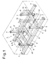
- Fig. 1 is a perspective view of a first embodiment of a module frame assembled according to the present invention;
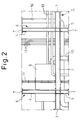
- Fig. 2 is a side view thereof;
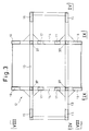
- Fig. 3 is a plan view of a device for assembling a module frame as shown in Fig. 1;
- Fig. 4 is a sectional view on the line IV-IV in Fig. 3;
- Fig. 5 is an enlarged view of part of Fig. 4;
- Fig. 6 is a view in the direction of the arrow VI in Fig. 5;
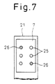
- Fig. 7 is a view in the direction of the arrow VII in Fig. 5;
- Fig. 8 is a view in the direction of the arrows VIII-VIII in Fig. 3;
- Fig. 9 is a view in the direction of the arrows IX-IX in Fig. 3;
- Figs. 10 to 16 are views showing the first to seventh steps, respectively of assembling a module frame by use of the assembling device of Fig. 3;
- Fig. 17 is a perspective view of a module assembly which is a combination of two or more module frames as shown in Fig. 1;
- Fig. 18 is a perspective view showing the module assembly of Fig. 17 installed in a larger structure;
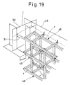
- Fig. 19 is an enlarged view of part of Fig. 18;
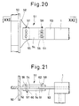
- Fig. 20 is an enlarged side view of the coupler seen in Fig. 19;
- Fig. 21 is a sectional view on the line XXI-XXI in Fig. 20;
- Fig. 22 is a perspective view showing a second embodiment of module frame manufactured according to the present invention; and
- Figs. 23 to 30 are perspective views showing the third to tenth embodiments respectively of module frame manufactured according to the present invention;
- Figs. 1 and 2 show a typical basic form of
module frame 1 manufactured according to the present invention which comprises a pair of horizontal, parallelmain beams 2, a pair of horizontal,parallel beam members 3 extending perpendicular to and between themain beams 2 and rigidly welded at their opposite ends to themain beams 2 and foursupport columns 6 each having upper andlower column portions main beams 2 with thebeam members 3. - A
flanged connector 7 is rigidly welded in position at a predetermined position, the connector-mounting position, or on each end of eachcolumn 6 andmain beam 2. - In the figures,
reference numeral 8 represents an auxiliary beam added to support fittings such asheavy machinery 9; 3, extensions for connecting themodule frame 1 to a stationary member of a hull structure, such as a bulkhead, when themodule frame 1 is installed in a ship; 45, reinforcement ribs; and 46, reinforcement brackets. - The
module frame 1 is assembled so that its width, length and height concur with a high accuracy with the size of a hexahedral container shown in phantom lines. - In addition to the
machinery 9, themodule frame 1 has fittings, such aspiping 10 andwiring 11, mounted on it. - The
module frame 1 may be assembled with the aid of thedevice 12 shown in Figs. 3 to 9. - As shown in Fig. 3, a pair of parallel,
longitudinal frames 13 having the same spacing as that of themain beams 2 of themodule frame 1 and longer than thebeams 2 are connected to a pair oflateral frames 14 extending perpendicular to thelongitudinal frames 13 and having the same spacing as that of thebeam members 3 of themodule frame 1. Fixed side positioning means 15 are mounted on one end of eachlongitudinal frame 13 to position themain beams 2 in the longitudinal, lateral and vertical directions and moving side positioning means 16 are mounted on the other ends of theframes 13. - Beam supports 17 are mounted on the upper surfaces of the
lateral frames 14 between thelongitudinal frames 13 and have the same height as that of thelower column portions 5 of themodule frame 1. Anupper positioning bases 18 having substantially the same height as that of theupper column portions 4 of themodule frame 1 are fixed at each end of thelateral frames 14. - As shown in Figs. 4, 5 and 6 in detail, the moving side positioning means 16 comprises a
movable base 22 which is movable byliner rollers 20 or the like along the length of thelongitudinal frames 13 and which has aconnector support bracket 21 thereon for lateral positioning of the associatedbeam member 2. Thebase 22 and thesupport bracket 21 are movable by acylinder 23. - The
support bracket 21 has an inner surface 24 (see Fig. 5) to which theflanged connector 7 is fixed with high positional accuracy and for example, as shown in Fig. 7,reamer pins 26 are inserted into two opposed throughholes 25 and bolts and nuts (not shown) are used for connecting through theother holes 25. - The
movable base 22 has a main-beam positioning base 32 at a position inside thesupport bracket 21. As shown in Fig. 6, thepositioning base 32 has aguide member 30 with apositioning block 28 for engaging at two vertically spaced positions one side surface of avertical web 27 of the I-shapedmain beam 2 for longitudinal and lateral positioning of themain beam 2, aguide member 30′ with a pushingcylinder 29 for pushing the other side surface of theweb 27 towards thepositioning block 28 and aheight positioning plate 31 for supporting thevertical web 27 so that the lower surface of themain beam 2 is coplanar with the tops of thelower column portions 5. - The moving side positioning means 16 has a
stationary base 19 whose inner end has apositioning stop 35 which themovable base 22 may engage so that the spacing between thesupport bracket 21 and asupport bracket 33 on the fixed side positioning means (see Fig. 4) can be maintained constant with high accuracy. - The fixed side positioning means 15 has, as shown in Fig. 4, a
connector 33 and a main-beam positioning base 34 which are of the same arrangement and of the same height as those of thesupport bracket 21 and thepositioning base 32 of the moving side positioning means 16. - Each of the junctions of the
longitudinal frames 13 with the lateral frames 14 has at its upper surface asupport bracket 37 which has the same structure as that of thesupport bracket 21 as shown in Fig. 7 to effect positioning through tightening of aflanged connector 36 rigidly attached to the lower end of thelower column portion 5. - The
upper positioning base 18 has at its top aguide member 39 with afrustoconical guide hole 38. Anupper guide bar 41 withfrustoconical guide projections 40 on the lower surface of its ends extends over thebases 18 and engage with the latter by engagement of theprojections 40 into theholes 38 thereby maintaining the height of theguide bar 41 constant. Upper positioning means 42 is thus provided. - The
upper guide bar 41 has on its bottomsurface support brackets 43 which are vertically aligned with thesupport brackets 37 and have the same structure as that of the latter so as to fix theconnectors 7 on the tops of theupper column portions 4 in position. Theupper guide bar 41 has suspension hooks 44 on its upper surface. - The method of assembly of the
module frame 1 will now be described with reference to Figs. 10 to 16 and Figs. 3 to 9. - Firstly, as shown in Fig. 10, the lower column supports 5 are positioned and secured by the
flanges 36 to thesupport brackets 37 at the junctions of thelongitudinal frames 13 with the lateral frames 14. - As shown in Fig. 11, the
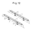
connectors 7 are positioned and mounted on thesupport brackets main beams 2 is positioned on the mainbeam positioning bases movable base 22 is moved forward to abut on thepositioning stop 35, so that the associatedconnector 7 is positioned with respect to the length of themodule frame 1. The positioning in the longitudinal and lateral directions is performed by theguide member 30 and the pushingcylinder 29 of the mainbeam positioning bases height positioning plate 31. - Next, as shown in Fig. 12, the
reinforcement ribs 45 are attached by welding at the required points on themain beam 2. - Then, as shown in Fig. 13, the
beam members 3 and theauxiliary beams 8 are mounted between themain beams 2 and theextensions 3′ are mounted on the outer side by welding. As shown in Fig. 14, thebrackets 46 are welded on for reinforcement. - As shown in Figs. 8 and 9, the upper guide bars 41 with the
support brackets 43 mounted at predetermined positions thereon are placed on the upper positioning bases 18 such that theguide projections 40 of the former are engaged in the guide holes 38 of the latter. Theupper column portion 4 is erected on each of the junctions of themain beams 2 andbeam members 3, as shown in Fig. 15, and its positions adjusted such that the upper end of theportion 4 is aligned with thecorresponding support bracket 43 and then is rigidly welded at its lower end to the corresponding junction. - After the welding any welding distortion is eliminated by restraining each portion until the welded portions have cooled down.
- Next, as shown in Fig. 16, the upper ends of the
lower column portions 5 whose position is fixed, are connected to themain beams 2. Each end of themain beams 2 and the upper ends of theupper column portions 4 are welded and thus connected to theconnectors 7, whose position is fixed, and welding distortion is eliminated by the same procedure as described above. In this connection, thelower column portions 5 may be regarded as being integral with the associatedconnectors 7 since they are of short length and are thus subject to less welding distortion. - By the above procedure, a
module frame 1 can be assembled with high accuracy. - It is advisable that the components such as the
main beams 2,beam members 3 and upper andlower column portions module frame 1 are accurately prepared in advance by cutting and the like to be slightly undersized, e.g. by 0 to -2 mm, relative to the specified final size. - It is also advisable to weld the
main beams 2,beam members 3 andupper column portions 4 at a different place and to use the assemblingdevice 12 of the present invention only for welding them to theconnectors 7. Themain beams 2,beam members 3 andsupport columns 6 should have sufficient rigidity to support the weight of machinery to be installed on them and also to be substantially resistant to vibration. Though I-shaped beams are used in the above embodiment, H-shaped, grooved, rectangular or round shape beams or composite materials may be used instead. - When the
module frame 1 thus formed is used for fitting out a large structure, such as the engine room of a large ship, several moduleframes carrying machinery 9, piping 10, wiring 11, etc., as shown in Fig. 1, are assembled together on a base by bolt-connecting theconnectors 7 and by connecting the piping 10 and wiring so as to form amodule frame assembly 48 in which all or part of the fittings which are functionally related to each other are present and which has a size installable in the hull (see Fig. 17). - Such a
module frame assembly 48 is prepared for each function, and each of theseassemblies 48 is installed and arranged three-dimensionally at a predetermined position in the engine room. As shown in Fig. 18, a connection is effected between the engine room floor and theassemblies 48, between each of theseassemblies 48 as well as between theassemblies 48 and atransverse bulkhead 49 or alongitudinal bulkhead 50 of the engine room. - As shown in Figs. 19 to 21, a
coupler 51 for coupling themodule frame 1 to thelongitudinal bulkhead 50 comprises twoplates 54 which sandwich twoelbow plates bulkhead 50 and themodule frame 1 from opposite sides and are connected to them bybolts portions plates holes 61 are shown as being slots by dotted lines. - The
module frame 1 described above is designed in container size (size for containerization) and is easy to transport. Accordingly, the work to install or mount various types ofmachinery 9 can be carried out at a remote place with a better working environment than the ship's engine room. Since the fittings can be functionally divided and installed on different module frames according to their function, it is possible to improve the accuracy of installing or mounting fittings on the module frames and to standardize the moduleframe work assembly 48. Further, it is possible to have an efficient three-dimensional arrangement effectively utilizing the space available since themodule frame 1 is designed as a three-dimensional structure of the form of "#". Moreover, such module frames 1 can be easily connected together with high accuracy since they have fewer points to be connected as compared to box type structures. - Connection of the
module frame 1 to thelongitudinal bulkhead 50 by thecoupling 51 described above is advantageous in that, when rapid oscillation or vibration occurs on a ship and an excessive load is applied to the bolt-tightenedportions module frame 1 is prevented by relative sliding motion between theplates plates portion module frame 1 and no high external force is applied to the fittings installed on themodule frame 1, which contributes to the safety of theassembly 48. - Slots may be provided for any of the
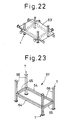
bolts 59 to 62. - Fig. 22 shows a second embodiment of the module frame according to the present invention which is substantially the same as the first embodiment except for the provision of an
additional floor 63 and therefore achieves the same effects and advantages as those of the first embodiment. - Fig. 23 represents a third embodiment of the module frame according to the present invention in which a
module frame 67 is formed by assemblingmain beams 64 andbeam members 65 to product a rectangular shape.Support columns 66 are connected to the four apexes of the rectangle. - Fig. 24 shows a fourth embodiment which is similar to the third embodiment except that the
module frame 70 has an intermediatetransverse beam member 68 andintermediate support columns 69 at the central portion of themain beams 64. - Fig. 25 shows a fifth embodiment which is substantially the same as the second embodiment except that the
module frame 73 also has uppermain beams 71 andupper beam members 72. - Fig. 26 shows a sixth embodiment in which the
module frame 75 comprises arectangular floor member 74,support columns 66 connected at a point between their ends to respective apexes of thefloor member 74 andupper beam members 72 connecting the upper ends of thesupport columns 66. - Fig. 27 shows a seventh embodiment in which the
module frame 76 comprises arectangular floor member 74,support columns 66 connected at their lower ends to the apexes of thefloor member 74, and uppermain beams 71 andupper beam members 72 transverse thereto to the connected upper ends of thesupport columns 66. - Fig. 28 shows an eighth embodiment which is substantially the same as the fourth embodiment except that the
module frame 78 includeslower support columns 73 in place of thecolumns - Fig. 29 shows a ninth embodiment in which the
module frame 81 comprisesmain beams 64,beam members 65,auxiliary crossbeams 79 andbeams 80 inside theparts lower floor members 74 andlower support columns 77 on thelower floor member 74. - Fig. 30 shows a tenth embodiment which is essentially two-dimensional. The
module frame 82 is composed only ofmain beams 64 andbeam members 65. - The second to tenth embodiments all achieve substantially the same effects and advantages as the first embodiment.
- In the embodiments described above, the module frames 1, 67, 70, 73, 75, 78, 81 and 82 are interconnected by bolt-connecting the mutually abutting
connectors 7. - In the above description the module frames are designed of container size. However, this is not essential and they may be of any size. Also, the embodiments have been described for application to ships; however, the present invention may be applied also to the manufacture of modules for all types of mechanical plant including other marine structures or land structures.
Claims (6)
- A method of assembling a module frame for assembly as part of a larger structure with a generally flat shape, the module frame (82) comprising a pair of horizontal and parallel main beams (64), a pair of beam members (65) connected to and extending between the main beams and a connector (7) connected to at least one end of each main beam and/or each beam member, the method comprising supporting the components (64, 65) of the module frame (82), whilst welded together, on a support device (12) in a predetermined position, retaining two or more connectors (7) on respective connector support brackets (21, 33) forming part of the support device (12), positioning the connector support brackets (21, 33) so that they are in predetermined positions with respect to one another adjacent respective ends of the said components (64, 65) and welding the connectors (7) to the said ends.
- A method of assembling a module frame for assembly as part of a larger structure of three-dimensional shape on which fittings are to be mounted, the module frame (1) comprising a pair of horizontal and parallel main beams (2), a pair of beam members (3) connected to and extending between the main beams, a support column (6) extending vertically from each junction of the main beams with the beam members and a connector (7) connected to at least one end of each main beam and/or each beam member and/or each support column, the method comprising supporting the components (2, 3, 6) of the module frame (1), whilst welded together, on a support device (12) in a predetermined position, retaining two or more connectors (7) on respective connector support brackets (21, 33) forming part of the support device (12), positioning the connector support brackets (21, 33) so that they are in predetermined positions with respect to one another adjacent respective ends of the said components (2, 3, 6) and welding the connectors (7) to the said ends.
- A method of assembling a module frame for assembly as part of a larger structure of three-dimensional shape on which fittings are to be mounted, the module frame (75) comprising a horizontal and substantially rectangular floor member (74), a support column (66) extending vertically from each corner of the floor member and a connector (7) connected to at least one end of each support column, the method comprising supporting the components (74, 66) of the module frame (75), whilst welded together, on a support device (12) in a predetermined position, retaining two or more connectors (7) on respective connector support brackets (21, 33) forming part of the support device (12), positioning the connector support brackets (21, 33) so that they are in predetermined positions with respect to one another adjacent respective ends of the support columns (66) and welding the connectors (7) to the said ends.
- A method as claimed in any one of Claims 1 to 3 which comprises positioning the said components (64, 65; 2, 3, 6; 74, 66) with respect to one another, welding them together, removing weld distortion of the welded portions and subsequently connecting the connectors (7) to at least some of the said components.
- A modular structure comprising a plurality of frame modules assembled by a method as claimed in any one of the preceding claims connected together by means of their connectors (7), the connectors (7) of each frame module being in predetermined positions with respect to one another, the modular structure being accommodated within a larger structure, such as a ship's engine room, and at least one of the frame modules (1) being connected to the larger structure by a coupler comprising two elbow plates (52, 53) connected to the frame module (1) and the larger structure, respectively, and two further plates (54) connected to opposite sides of the elbow plates by bolts (55, 56) which pass through holes (59, 60, 61, 62), at least some of which are optionally in the form of elongate slots.
- A modular structure comprising a plurality of frame modules assembled by a method as claimed in any one of Claims 1 to 4 connected together by means of their connectors (7), the connectors (7) of each frame module being in predetermined positions with respect to one another, the modular structure being accommodated within a larger structure, such as a ship's engine room, and at least one of the frame modules (1) being connected to the larger structure by a coupler comprising a guide rail (91) which is secured to the larger structure and serves to reinforce it.
Applications Claiming Priority (10)
| Application Number | Priority Date | Filing Date | Title |
|---|---|---|---|
| JP2218160A JPH04100791A (en) | 1990-08-21 | 1990-08-21 | Outfitting method for marine engine room |
| JP218160/90 | 1990-08-21 | ||
| JP289678/90 | 1990-10-26 | ||
| JP1990112285U JPH0469389U (en) | 1990-10-26 | 1990-10-26 | |
| JP112285/90 | 1990-10-26 | ||
| JP2289678A JPH04163288A (en) | 1990-10-26 | 1990-10-26 | Coupling tool |
| JP2292444A JP2932671B2 (en) | 1990-10-30 | 1990-10-30 | Method and apparatus for assembling module frame of large structure |
| JP292444/90 | 1990-10-30 | ||
| JP294127/90 | 1990-10-31 | ||
| JP02294127A JP3141392B2 (en) | 1990-10-31 | 1990-10-31 | Module frame for machine plant |
Publications (2)
| Publication Number | Publication Date |
|---|---|
| EP0473357A1 EP0473357A1 (en) | 1992-03-04 |
| EP0473357B1 true EP0473357B1 (en) | 1996-05-22 |
Family
ID=27526548
Family Applications (1)
| Application Number | Title | Priority Date | Filing Date |
|---|---|---|---|
| EP91307707A Expired - Lifetime EP0473357B1 (en) | 1990-08-21 | 1991-08-21 | Module frames |
Country Status (5)
| Country | Link |
|---|---|
| US (2) | US5226583A (en) |
| EP (1) | EP0473357B1 (en) |
| KR (1) | KR0130966B1 (en) |
| BR (1) | BR9103581A (en) |
| DE (1) | DE69119669T2 (en) |
Families Citing this family (26)
| Publication number | Priority date | Publication date | Assignee | Title |
|---|---|---|---|---|
| US5226583A (en) * | 1990-08-21 | 1993-07-13 | Ishikawajima-Harima Jukogyo Kabushiki Kaisha | Module frame work for larger structure, method and device for assembling module frame work and coupler for module frame work |
| DE4139542C2 (en) * | 1991-11-30 | 1999-12-30 | Thyssen Nordseewerke Gmbh | Ship, especially merchant ship |
| JP3219513B2 (en) * | 1992-12-24 | 2001-10-15 | 石川島播磨重工業株式会社 | Joint structure of synthetic resin structural material |
| US5579622A (en) * | 1994-04-22 | 1996-12-03 | Banks Lumber Co., Inc. | Floor frame assembly |
| DE19532107C2 (en) * | 1995-08-31 | 1997-10-16 | Thyssen Nordseewerke Gmbh | Ship with horizontally extending flat surface elements arranged in the hull |
| US6035590A (en) * | 1997-04-29 | 2000-03-14 | Lindsay; Frederick H. | Peripheral beam system for manufactured home |
| US5992121A (en) * | 1997-06-19 | 1999-11-30 | Lindsay; Fredrick H. | Modular support assembly |
| US5970676A (en) * | 1997-06-19 | 1999-10-26 | Lindsay; Fredrick H. | Outrigger support for building structure |
| US6018921A (en) * | 1997-09-27 | 2000-02-01 | Lindsay; Fredrick H. | Transverse truss for building structure |
| US6457291B2 (en) * | 1998-03-31 | 2002-10-01 | Wick Building Systems, Inc. | Floor frame structural support assembly and a method of making the same |
| US6254132B1 (en) | 1998-08-07 | 2001-07-03 | Fredrick H. Lindsay | Frame for transporting a building structure on a wheel assembly |
| FR2804709B1 (en) * | 2000-02-09 | 2002-04-19 | Campenon Bernard Sge | DEVICE FOR LIMITING THE RELATIVE MOVEMENT OF TWO ELEMENTS OF A CIVIL ENGINEERING STRUCTURE AND STRUCTURE COMPRISING SUCH A DEVICE |
| US6920721B2 (en) * | 2002-06-05 | 2005-07-26 | Adv-Tech Building Systems, Llc | Building system |
| GB2404899B (en) * | 2003-08-13 | 2006-11-08 | Trident Offshore Ltd | Buoy and method of manufacturing same |
| US7278650B2 (en) | 2004-03-29 | 2007-10-09 | Heartland Recreational Vehicles, Llc | Travel trailer having improved turning radius |
| US7926694B2 (en) * | 2005-10-14 | 2011-04-19 | Enrique Franco | Apparatus for vertically manufacturing poles and columns |
| KR101103160B1 (en) * | 2008-12-17 | 2012-01-04 | 에스티엑스조선해양 주식회사 | Welding method of coupler base socket of LNG carrier and quality evaluation method of coating film formed on back surface of coupler base socket welding surface |
| WO2010076814A1 (en) * | 2008-12-29 | 2010-07-08 | Fincantieri Cantieri Navali Italiani S.P.A. | Conditioning station for naval application and assembly method thereof |
| JP6871698B2 (en) * | 2016-09-08 | 2021-05-12 | Ntn株式会社 | Water wheel suspension device |
| US9903111B1 (en) * | 2017-02-14 | 2018-02-27 | Orial Nir | Construction assembly and method for laying blocks |
| CN108838602B (en) * | 2018-07-11 | 2020-08-11 | 中车唐山机车车辆有限公司 | Welding tool for vehicle body framework |
| CN109048760B (en) * | 2018-08-20 | 2020-07-14 | 滁州市经纬装备科技有限公司 | Platform assembly |
| CN110435814A (en) * | 2019-08-25 | 2019-11-12 | 李长明 | A kind of film applicator coating builds the chemicals cabin method of construction of chemical tanker |
| CN115367045B (en) * | 2022-08-30 | 2025-04-15 | 中船澄西船舶修造有限公司 | A vibration-resistant reinforcement structure between the main engine room and the oil separator room |
| CN116968893B (en) * | 2023-05-04 | 2026-01-27 | 江南造船(集团)有限责任公司 | Installation method for non-allowance butt joint of equipment unit modules |
| CN119870868B (en) * | 2025-03-25 | 2025-07-04 | 中国建筑第五工程局有限公司 | Welding positioning device for large-span steel structure building construction |
Family Cites Families (20)
| Publication number | Priority date | Publication date | Assignee | Title |
|---|---|---|---|---|
| US384196A (en) * | 1888-06-05 | Mond duval | ||
| US1883376A (en) * | 1927-10-20 | 1932-10-18 | Hilpert Meier George | Building construction |
| US1804420A (en) * | 1930-01-13 | 1931-05-12 | Raymond E Kelley | Ceiling supporting strap |
| US2070937A (en) * | 1932-08-19 | 1937-02-16 | Stanley F L Vallet | Means for constructing buildings |
| US2176926A (en) * | 1935-07-26 | 1939-10-24 | Pennsylvania Shipyards Inc | Reconditioned ship and method of installing internal bulkheads in ships |
| US2240310A (en) * | 1939-10-14 | 1941-04-29 | St Louis Aircraft Corp | Airfoil |
| US2555782A (en) * | 1947-04-29 | 1951-06-05 | Raymond G Brownstein | Scaffold structure |
| US2902247A (en) * | 1955-12-23 | 1959-09-01 | Clark Equipment Co | Clamping means |
| GB1016790A (en) * | 1962-07-21 | 1966-01-12 | Wagner Hochdruck Dampfturbinen | Ship's drive installation having a plurality of driving engines |
| US3363597A (en) * | 1966-07-27 | 1968-01-16 | Gen Dynamics Corp | Ship and method of construction |
| US3543951A (en) * | 1968-07-19 | 1970-12-01 | Midland Ross Corp | Cargo-container stack and stack reinforcing and lash-down apparatus |
| US3828515A (en) * | 1969-12-16 | 1974-08-13 | G Galgoczy | Non-slip, high strength bolted joints |
| JPS4964542A (en) * | 1972-10-25 | 1974-06-22 | ||
| US3849012A (en) * | 1973-10-24 | 1974-11-19 | T Krouse | Building structure fastener |
| US3977147A (en) * | 1974-10-25 | 1976-08-31 | Nasa | Flanged major modular assembly jig |
| US4014089A (en) * | 1975-02-21 | 1977-03-29 | Kajima Corporation | Method of connecting beams and columns of steel frame construction |
| DE3305323A1 (en) * | 1983-02-16 | 1984-08-16 | Blohm + Voss Ag, 2000 Hamburg | SHIP WITH A PIPELINE SYSTEM LOCATED ON THE INNER FLOOR |
| DE3426333A1 (en) * | 1984-07-17 | 1986-01-30 | Blohm + Voss Ag, 2000 Hamburg | DRIVE UNIT FOR SHIPS |
| US4805859A (en) * | 1987-11-05 | 1989-02-21 | Don Hudson | Apparatus for securing containers to moving platforms |
| US5226583A (en) * | 1990-08-21 | 1993-07-13 | Ishikawajima-Harima Jukogyo Kabushiki Kaisha | Module frame work for larger structure, method and device for assembling module frame work and coupler for module frame work |
-
1991
- 1991-08-14 US US07/745,246 patent/US5226583A/en not_active Expired - Lifetime
- 1991-08-20 KR KR1019910014306A patent/KR0130966B1/en not_active Expired - Lifetime
- 1991-08-21 EP EP91307707A patent/EP0473357B1/en not_active Expired - Lifetime
- 1991-08-21 BR BR919103581A patent/BR9103581A/en not_active IP Right Cessation
- 1991-08-21 DE DE69119669T patent/DE69119669T2/en not_active Expired - Lifetime
-
1993
- 1993-03-04 US US08/026,012 patent/US5347703A/en not_active Expired - Lifetime
Also Published As
| Publication number | Publication date |
|---|---|
| US5226583A (en) | 1993-07-13 |
| DE69119669D1 (en) | 1996-06-27 |
| DE69119669T2 (en) | 1996-10-02 |
| BR9103581A (en) | 1992-05-12 |
| KR920004234A (en) | 1992-03-27 |
| EP0473357A1 (en) | 1992-03-04 |
| KR0130966B1 (en) | 1998-04-11 |
| US5347703A (en) | 1994-09-20 |
Similar Documents
| Publication | Publication Date | Title |
|---|---|---|
| US5226583A (en) | Module frame work for larger structure, method and device for assembling module frame work and coupler for module frame work | |
| US7143585B2 (en) | Turbine power plant, installation process and removal process of the turbine power plant | |
| US7552903B2 (en) | Machine mounting system | |
| JP2684439B2 (en) | Track-type transportation system, particularly magnetic levitation railway track structure support method and manufacturing method thereof | |
| KR101281644B1 (en) | Lashing method and apparatus for marine transportation of hull block | |
| WO2002047959A1 (en) | Arrangement for connecting vehicle chassis beams | |
| JPH04171397A (en) | Modular frame for mechanical plants | |
| US20090120020A1 (en) | Composite integrated module | |
| CN1059124A (en) | Modular frame of large structure, method and device for assembling modular frame, and coupler for modular frame | |
| US4490066A (en) | Clamping system for heavy "I" beams and the like on oil rigs, etc. | |
| EP0484099B1 (en) | Method of installing fittings on a module frame | |
| KR101841493B1 (en) | Cover structure for vehicle passage using deck plate and construction method of it | |
| KR200465783Y1 (en) | Floor beam for engine assembly and test | |
| JP2855843B2 (en) | How to attach fittings to the module frame | |
| JPH05179703A (en) | Connector for h-steels | |
| CN1046245C (en) | Module frame work for larger structure, method and device for assembling module frame work and coupler for module frame work | |
| CN222496443U (en) | Auxiliary frame, chassis and vehicle | |
| EP4729403A1 (en) | Re-usable grillage system and methods for module transportation | |
| JP4713291B2 (en) | Split structure and assembly method of large steel H-beam | |
| KR20160139623A (en) | Structure and carrying out method for bulkhead block of ship | |
| CN221291203U (en) | A comprehensive transmission device disassembly and assembly rack | |
| CN121985503A (en) | Prefabricated modular skid system for data centers and its manufacturing method | |
| KR20250177005A (en) | Modular structure | |
| SU1712241A1 (en) | Method of forming ship engine room unit | |
| JP2932671B2 (en) | Method and apparatus for assembling module frame of large structure |
Legal Events
| Date | Code | Title | Description |
|---|---|---|---|
| PUAI | Public reference made under article 153(3) epc to a published international application that has entered the european phase |
Free format text: ORIGINAL CODE: 0009012 |
|
| AK | Designated contracting states |
Kind code of ref document: A1 Designated state(s): DE FR GB NL |
|
| 17P | Request for examination filed |
Effective date: 19920902 |
|
| 17Q | First examination report despatched |
Effective date: 19931208 |
|
| GRAH | Despatch of communication of intention to grant a patent |
Free format text: ORIGINAL CODE: EPIDOS IGRA |
|
| GRAA | (expected) grant |
Free format text: ORIGINAL CODE: 0009210 |
|
| AK | Designated contracting states |
Kind code of ref document: B1 Designated state(s): DE FR GB NL |
|
| REF | Corresponds to: |
Ref document number: 69119669 Country of ref document: DE Date of ref document: 19960627 |
|
| ET | Fr: translation filed | ||
| PLBE | No opposition filed within time limit |
Free format text: ORIGINAL CODE: 0009261 |
|
| STAA | Information on the status of an ep patent application or granted ep patent |
Free format text: STATUS: NO OPPOSITION FILED WITHIN TIME LIMIT |
|
| 26N | No opposition filed | ||
| REG | Reference to a national code |
Ref country code: GB Ref legal event code: IF02 |
|
| PGFP | Annual fee paid to national office [announced via postgrant information from national office to epo] |
Ref country code: NL Payment date: 20100814 Year of fee payment: 20 |
|
| PGFP | Annual fee paid to national office [announced via postgrant information from national office to epo] |
Ref country code: DE Payment date: 20100818 Year of fee payment: 20 Ref country code: FR Payment date: 20100824 Year of fee payment: 20 |
|
| PGFP | Annual fee paid to national office [announced via postgrant information from national office to epo] |
Ref country code: GB Payment date: 20100818 Year of fee payment: 20 |
|
| REG | Reference to a national code |
Ref country code: DE Ref legal event code: R071 Ref document number: 69119669 Country of ref document: DE |
|
| REG | Reference to a national code |
Ref country code: DE Ref legal event code: R071 Ref document number: 69119669 Country of ref document: DE |
|
| REG | Reference to a national code |
Ref country code: NL Ref legal event code: V4 Effective date: 20110821 |
|
| PG25 | Lapsed in a contracting state [announced via postgrant information from national office to epo] |
Ref country code: GB Free format text: LAPSE BECAUSE OF EXPIRATION OF PROTECTION Effective date: 20110820 |
|
| PG25 | Lapsed in a contracting state [announced via postgrant information from national office to epo] |
Ref country code: NL Free format text: LAPSE BECAUSE OF EXPIRATION OF PROTECTION Effective date: 20110821 |
|
| PG25 | Lapsed in a contracting state [announced via postgrant information from national office to epo] |
Ref country code: DE Free format text: LAPSE BECAUSE OF EXPIRATION OF PROTECTION Effective date: 20110822 |