US3363597A - Ship and method of construction - Google Patents
Ship and method of construction Download PDFInfo
- Publication number
- US3363597A US3363597A US568251A US56825166A US3363597A US 3363597 A US3363597 A US 3363597A US 568251 A US568251 A US 568251A US 56825166 A US56825166 A US 56825166A US 3363597 A US3363597 A US 3363597A
- Authority
- US
- United States
- Prior art keywords
- ship
- module
- modules
- matrix
- construction
- Prior art date
- Legal status (The legal status is an assumption and is not a legal conclusion. Google has not performed a legal analysis and makes no representation as to the accuracy of the status listed.)
- Expired - Lifetime
Links
Images


Classifications
-
- B—PERFORMING OPERATIONS; TRANSPORTING
- B63—SHIPS OR OTHER WATERBORNE VESSELS; RELATED EQUIPMENT
- B63B—SHIPS OR OTHER WATERBORNE VESSELS; EQUIPMENT FOR SHIPPING
- B63B3/00—Hulls characterised by their structure or component parts
-
- B—PERFORMING OPERATIONS; TRANSPORTING
- B63—SHIPS OR OTHER WATERBORNE VESSELS; RELATED EQUIPMENT
- B63B—SHIPS OR OTHER WATERBORNE VESSELS; EQUIPMENT FOR SHIPPING
- B63B3/00—Hulls characterised by their structure or component parts
- B63B3/02—Hulls assembled from prefabricated sub-units
-
- B—PERFORMING OPERATIONS; TRANSPORTING
- B63—SHIPS OR OTHER WATERBORNE VESSELS; RELATED EQUIPMENT
- B63B—SHIPS OR OTHER WATERBORNE VESSELS; EQUIPMENT FOR SHIPPING
- B63B3/00—Hulls characterised by their structure or component parts
- B63B3/02—Hulls assembled from prefabricated sub-units
- B63B3/08—Hulls assembled from prefabricated sub-units with detachably-connected sub-units
-
- B—PERFORMING OPERATIONS; TRANSPORTING
- B63—SHIPS OR OTHER WATERBORNE VESSELS; RELATED EQUIPMENT
- B63B—SHIPS OR OTHER WATERBORNE VESSELS; EQUIPMENT FOR SHIPPING
- B63B73/00—Building or assembling vessels or marine structures, e.g. hulls or offshore platforms
- B63B73/20—Building or assembling prefabricated vessel modules or parts other than hull blocks, e.g. engine rooms, rudders, propellers, superstructures, berths, holds or tanks
-
- B—PERFORMING OPERATIONS; TRANSPORTING
- B63—SHIPS OR OTHER WATERBORNE VESSELS; RELATED EQUIPMENT
- B63B—SHIPS OR OTHER WATERBORNE VESSELS; EQUIPMENT FOR SHIPPING
- B63B73/00—Building or assembling vessels or marine structures, e.g. hulls or offshore platforms
- B63B73/40—Building or assembling vessels or marine structures, e.g. hulls or offshore platforms characterised by joining methods
- B63B73/43—Welding, e.g. laser welding
Description
Jan. 16, 1968 A. M. ZEIEN 3,363,597
SHIP AND METHOD OF CONSTRUCTION Filed July 27, 1966 4 Sheets-Sheet l FABRICATION ERECTION k FITTING OUT (MAKING OF (ASSEMBLY U M (INSTALLATION BLOCKS ON OF BLOCKS '8 OF EQUIPMENT LAND) ON WAYS) H AT DOCKSIDE) 2/ 22 OLD METHOD Z3 24 FIG.
3'! NEW METHOD 3'5 m I FABRICATION ERECTION OF BLOCKS (ASSEMBLY INSERTION FOR HULL OF HULL OF CRID ENVELOPE (ON WAYS) ONLY (ON LAND ON WAYS) k 34 35 FABRICATION W OF GRID I LAUNCH (0N LAND) 36 ?7 I 7 FABRICATION INSERTION OF MODuLEs 7 OF MODULES (ON LAND) (AT DOCKSIDE) FITTING OUT (INTERCONNECTINC OF MODuLEs AT DOCKSIDE) INVENTOR.
ALFRED M. ZEIEN F/fi. .2 BY
ATTORNEX Jan. 16, 1968 A. M. ZEIEN SHIP AND METHOD OF CONSTRUCTION 4 Sheets-Sheet 2 Filed July 27, 1966 INVENTOR. ALFRED M. ZEIEN fljwfli wfi A r TOR/V5 Y Jan. 16, 1968 A. M. ZEIEN 3,363,597
SHIP AND METHOD OF CONSTRUCTION Filed July 27, 1966 4 Sheets-Sheet 5 INVENTOR. ALFRED M. ZEIEN WZWAM ATTORNEY Jan. 16, 1968 A. M. ZEIEN SHIP AND METHOD OF CONSTRUCTION 4 Sheets-Sheet 4 Filed July 27, 1966 FIG. /0
INVENTOR. ALFRED M. ZEIEN ATTORNEY Unite States 3,363,597 SEEP AND METHGI) F CONSTRUCTION Alfred M. Zeien, Norwell, Mass., assignor to General Dynamics Corporation, New York, N.Y., a corporation of Delaware Filed July 27, 1966, Ser. No. 568,251 14 Claims. (Cl. 11465) ABSTRACT OF THE DISCLGSURE This invention relates to a novel method of constructing, assembling and fitting out a ship.
In methods of ship building up to the present day, there has been steady progress toward more efiicient assembling of the parts of the ship. Originally, as in the days of wooden ships, the frame of a ship was laid down on the ways and the plates of the ship, inside and outside, were attached to the frame on the ways. However, the major bottleneck in any shipyard is the available amount of way space, and since this original method of construction had everything taking place on the ways, it had decided limitations. The panel method of construction improved on the plate and frame method by attaching some of the plates such as the exterior plates to parts of the frame prior to assembly of the frame. This succeeded in removing some of the construction time from the ways but still required all interior construction to be done on the Ways. The block method superseded the panel method by making of whole sections of the ship on land and making these sections or blocks complete in and of themselves. These were then moved to the ways and attached. This method had the severe drawback for ships requiring many interior sections such as passenger ships, of having so many blocks that a substantial amount of time was taken on the ways in attaching the blocks together. Consequently, the trend continued toward larger and larger blocks formed on land, before assembly on the ways, until the point of diminishing returns was reached. At the present time, blocks as large as a third of a ship may be assembled on land and moved to the ways for assembly. The complexities involved in moving such huge pieces increase the costs of construction more than the savings in time on the Ways. Consequently, then it is considered that the block method of construction has reached its logical limit. If further improvements are to be made, a wholly new l'ipproach must be made to the problem of ship assem- The present invention provides a novel approach to ship building which reduces the time on the ways to a minimum without involving the transport of huge blocks from fabrication to the ways. According to the present invention, a hull envelope is constructed on the ways from blocks of an optimum size. Within the hull envelope, as assembled, there is a rectangular center space with vertical side walls occupying most of the ship. This center space is divided into compartments by bulkheads for reasons of ship flooding integrity. Within each of these compartments, while the ship is on the ways or after launching, an open matrix of girders, substantially fitting each compartment, is lowered into it. After the boat is launched and brought around along side a dock, modules comprising pre-assembled, self-contained units are lowered into grid openings in the matrix by cranes on the dock and suspended from the girders of the matrix within the ship. Connections between the modules are made by transition pieces. However, design of the modules to be as self contained as possible is done so as to keep the inter-connections at dockside to a minimum.
Accordingly, it is a nobject of the present invention to provide a method of ship construction which maximizes the proportion of fabrication done on land without requiring the transport of huge blocks of ship parts.
It is another object of the invention to provide a method of ship construction which reduces the time spent on the ways to an absolute minimum.
It is a further object of this invention to provide a method of ship construction which allows conversion of the ship rapidly from one function to another by replacing modules without an extensive amount of reconstruction.
It is yet another object of the invention to provide a method of ship construction which permits removal of most of the superstructure of a ship below deck, thereby providing greater seaworthiness and use of deck space for other useful purposes.
It is yet another object of the invention to provide a ship constructed by the above method.
Further objects of the invention will be seen by reference to the following description together with the following drawings in which like numerals represent like parts throughout:
FIGURE 1 shows a block flow diagram describing the old method of ship construction used up to the present day.
FIGURE 2 shows a block flow diagram of the new method according to the present invention.
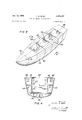
FIGURE 3 is an elevation of a ship hull envelope constructed in accordance with the present invention.
FIGURE 4 is a vertical section of a ship according to the present invention taken along the lines 44 of FIGURE 3.
FIGURE 5 is an elevation of a typical matrix according to the present invention.
FIGURE 6 is an elevation from below a typical module according to the present invention showing the internal parts thereof.
FIGURE 7 shows an elevation of a special type of module known as a reefer space.
FIGURE 8 shows a section of a transition piece for connecting ducts between modules.
FIGURE 9 is a section of a typical support of a module on a girder of the matrix together with suitable connections to the module above.
FIGURE 10 shows a staircase module.
FIGURE 11 shows a variation of the means of supporting modules on the matrix girders according to the present invention.
FIGURE 12 shows a pictorial representation of a hull envelope floating at dockside with a crane on the dock lowering modules into a matrix according to the present invention.
In FIGURE 1 is shown the method of construction used up to the present, the first step 21 of which comprises fabrication of as much of the boat as possible into as large blocks as economically possible. The next step 22 comprises moving these large blocks from the fabrication area across land to the ways and assembly of the blocks into the ship. The third step 23 is to launch the boat, thereby getting it off the ways and leaving them free for the the next ship. The fourth step 24 comprises fitting out the ship at dockside by installation of all equipment which cannot be contained within the huge blocks, and interconnection of the blocks.
In FIGURE 2 the new method according to the present invention is illustrated. The first step 31 on land comprises fabrication of the blocks which constitute a part of the hull envelope. These blocks are made smaller than those of the old method thereby making it possible for installation on land of all equipment which is self-contained in each of these blocks. The second step 32 comprises moving of these smaller blocks across land to the ways, and assembly of the hull envelope. The parts of the ship which are thus assembled are referred to as the ship shape and comprise those parts which contact the water itself. They are the parts which must be assembled before the ship can float in the water. In the third step 33 the matrix in inserted into each compartment in the center of the ship. In the flow diagram of FIGURE 3, this is shown being done on the ways, but it may optionally be done after launch at dockside. The grid matrix has been fabricated in step 34 on land previously in either case. The method of the present invention requires that the hull envelope be constructed so as to be strong enough to support the ship without relying on decks or internal members. The portion of the ship which supports the ship as a whole in the water as distinguished from strength to hold machinery, etc., is called the section modulus. The present invention relies on the blocks forming the hull envelope, as well as the bulkheads, to form this section modulus. The matrices inserted in the center of the ship are attached to the hull envelope by any known means such as welding or bolting, but they are not relied on as a portion of the section modulus.
The next step 35 in the method according to the present invention is to launch the ship and to bring it around dockside for fitting out. At dockside the modules are inserted in step 36 into the matrix grid from the bottom up, that is, the modules at the bottom are put in place first. These modules have been previously fabricated on land in step 37 and contain all internal parts necessary for the operation or use of that particular module. As each module is lowered into the matrix it rests on the girders of the matrix grid by flanges or supporting girders, as will be shown subsequently. The module is then attached to the girders by known means such as welding so as to make it structurally firm. At this point any equipment which is customarily left free of the walls or hull of the ship itself, such as chairs, etc., may be lowered into each module as it is fixed in place. The last step 38 according to the present invention is the inter-connection of the modules. The modules are designed to be self-contained to reduce this inter-connection to a minimum. Interconnection is done by transition pieces which will be illustrated below. Of course, after the interior of the ship has been constructed according to the present invention, the superstructure of the ship is installed as in the prior art.
In FIGURE 3 a hull envelope assembled is shown. Bow pieces 41 will be self-contained as posible, containing all pieces of equipment which must be contained in the how. The side wall structure is formed by blocks 42, 43, and are separated at intervals by bulkheads 44, running the wdith of the ship. The base of the ship is formed by the bottom plates 45, on which the side walls 43 rest, as shown in FIGURE 4. At the rear of the ship are the stern blocks 46. These will be designed to contain as much of the propulsion equipment as is directly associated with the propeller shafts. If the boat is gas turbine electric, the rear blocks 46 will contain only the electric motor portion connected to the propeller shafts, and the gas turbine engine providing the power for the ship will be self-contained in another part of the ship, probably in one of the self-contained modules designed for the purpose. Interconnection of the electric generator driven by the turbine to the electric motor can easily be made by cable. In the bulkheads 44, above the level determined by marine architecture principles relating to flooding integrity, there will be pasageways 47 to provide communication from one compartment to the next. These will be designed so as to match reasonably with the decks formed by the modules positioned in the compartment. They will be provided with suitable doors, not shown. Cables and conduits which must of necessity run the entire length of the ship are positioned outside of the side wall blocks 42 behind the sheer strakes 48. These are shown by representation in FIGURE 4. The base blocks 45 contain, as is customary, tanks 49 for holding water, oil, or ballast. Side tanks 50 in the side blocks 43 are for the same purpose. These tanks as well as the cables and conduits behind sheer strakes 48 will be connected to the inner part of the ship through appropriate conduits not shown and will be connected with the internal machinery by transition pieces which will be shown subsequently.
FIGURE 5 shows a representation of a typical grid matrix 51. The grid openings between successive girders permit the introduction of modules which are suspended from the girders by flanges which will be described below. This matrix is four modules high and is designed to permit four modules in one direction and two modules in the other direction. If a module is typically 40 feet by 20 feet by 10 feet, the total size of a matrix 51 as illustrated in FIGURE 5 will be feet by 80 feet by 40 feet. In actual practice, there may be anywhere from 2 to 6 modules across the width of a ship, depending on the orientation of matrix '51. The internal width of the ship may be considered to run generally in the range from 80 to feet. Depending on the size of the ship as a whole, there may be anywhere from 4 to 8 compartments lengthwise. These compartments lengthwise may contain a total of anywhere from 10 to 28 modules. Although the representation of FIGURE 5 shows a plan of 2 modules by 4 modules in the horizontal plane, or grid, a grid may comprise 3 modules by 4 modules, or more. The limits on the size of the grid are essentially determined by the limits on the size of each compartment within the ship, and these are determined by principles of marine architecture relating to the flooding integrity of the Ship.
The girders of the matrix 51 are shown representationally as rods but may be formed by girders of any type such as T-beam, I-beam, U-beam, angle beam, or any other form of girder of suitable structural strength. Girders will be connected together by welding in a manner known in the art. Matrix 51 is fabricated on land by placing the top girders upside down on a level floor and welding the top grid. After vertical girders are welded in place, using plumb lines, each successive grid is put in place, taking care that all parts of each gird are on a level. When the entire matrix is complete, it may be lifted by crane, turned over, and inserted in a compartment. The matrix 51 as shown in FIGURE 5 is lowered into a compartment of a ship, and each girder where it approaches a wall is welded in place to fix the matrix firmly into the hull envelope. Suitable girders may be welded to the internal walls of the compartment to form supports for the outward extended flanges of the modules supported in the grid openings on the edges or at the corners.
In FIGURE 6 is shown a typical module comprising a ceiling and deck piece 52 which provides the main structural support for the module. Attached to the four edges of this ceiling piece 52 are flanges 53, which are attached securely enough to piece 52 to support the entire module on the four surrounding girders of the grid opening in which the module rests. The module is then suspended within the matrix 51 by flanges 53, and all components within the module are suspended from the ceiling piece 52. Equipment which must rest on the floor surface will be installed in advance on the top side of ceiling piece 52 of the module below. There are shown in the module illustrated in FIGURE 6 outer walls 54 and inner walls 55. Outer walls 54 will form the walls for the adjacent module as well as their own. Inner walls 55 divide the module into compartments. Since, as mentioned before, the typical size of such a module is 20 feet by 40 feet in J its horizontal plan, the modules will typically be far more sub-divided into rooms than is illustrated in FIG- URE 6. However, FIGURE 6 illustrates the manner in which this is done. In the inner and outer walls 54 and 55 of the module are provided door openings 56 providing communications with the remainder of the ship and within the module. These will be provided with suitable doors not shown. Suspended from the ceiling piece 52 is a piece of machinery 57, shown, for example, as a fan. This piece of machinery 57 is powered by a electric cord 58 which passes across the ceiling and down the wall to electrical plug 59 which pierces the wall 54 and will be connected to the next module or to a source of power after installation of the module in the matrix 51. The fan 57 is also provided with a conduit 60 for air or other fluid. This conduit 60 is led to a wall bracket 61 where an opening is provided. The appropriate fluid will be provided through this conduit 60 from the adjacent module by inter-connection with a transition piece which will be described subsequently. Although not shown, the conduit 60 might also have been led over to one of the edges of the module not containing a wall and positioned in suitable position for inter-connection with a transition piece connected to the wall of the next module. There is also shown a piece 62 of electrical equipment attached to the wall 54 of the module. This piece 62 of electrical equipment may be of any type whatever and is powered by a cord leading to a plug 63 which also leads through the wall 54- to a source of power. If the piece 62 of electrical equipment is heavy, it will be supported from the ceiling rather than hung from the wall for structural reasons. There is also shown within the module a double decker bed 64, which is attached to the wall. Beds and desks and any other equipment which is normally rested on the floor but positioned up against a wall will be suspended from the walls for installation purposes. When the module is positioned in place, extension legs can be positioned underneath the bed 64 or other equipment to make it rest its weight on the floor, since it would be too much of a strain to attempt to make the wall 54 carry the weight of persons and other equipment as well as the bed itself. Other equipment which is normally stationed away from the walls will be attached in advance to the topside of the ceiling piece 52 of the module below the module in question. The module as it is being lowered into the matrix 51 will contain exterior and interior walls suspended from it as well as heavy equipment suspended from the ceiling piece 52 and lighter equipment 62 suspended from the walls and some equipment (not shown) positioned on the topside of it for use in the module above. There is also shown in the module a ceiling light fixture 65 which is represented as fluorescent but which may be of any type which is compatible with ship safety regulations.
It will be noted in FIGURE 6 that there is a space 66 between wall 55 and flange 53 parallel to it. This space 66 is the means for providing in the modules themselves passageways for communications the length and width of the ship. Adjacent modules will have spaces in the same places and/or spaces intersecting and running perpendicular with space 66 in the module shown. By this means there are provided corridors in the ship without the necessity of providing separate spaces within the grid for horizontal passageways.
In FIGURE '7 is shown a special kind of module 79 called a reefer space. It is a compartment or series of compartments in which temperature and/or humidity must be controlled within narrow limits. One of the compartments would, for example, be a freezer. Another would be a higher temperature refrigerator. For some applications, there might also be a dry room. This kind of module must have a false floor due to the fact that insulation is provided in all the walls 71. As shown, there is in each compartment a temperature or humidity controlling unit 72 which may typically provide a heat exchanger. Conduit 73 will provide cold water to carry oflt heat removed in the heat exchanger. Conduit 73 will extend through the outer wall 71 of the reefer space at which point after installation of the modules there will be attached a transition piece for connection to a cold water conduit in the adjoining module. There is also contained in wall 71 an electric outlet '74 to provide power for the heat exchanger. There is also provided a door 75 which will be suitably insulated for the compartment. There are shown three such doors for three separate compartments in which the temperature and/or humidity must be kept at different values. Each compartment will carry its own heat exchange unit 72 and, if necessary, humidity control unit along with suitable temperature and humidity sensing devices to control the operation of the respective heat exchange units. When installed, the false floor of reefer space 70 rests a few inches above the ceiling piece of the module spaced below. The reefer space 70 is designed to be suspended from its grid opening by its ceiling piece as with the regular modules. There will be suitable base connections, not shown, to avoid gaps between the false floor of the reefer space 70 and the deck of the module below.
In FIGURE 8 is shown a transition piece 83 for conduits carrying fluids throughout the ship, either liquid or gas. The transition piece 81 is more or less cylindrical and has on each end a circular flange 82 which may be connected by either bolts or welding to the ends of conduits to be joined. The center portion of the transition piece '81 contains undulations or bellows bends 82 to provide needed flexibility. Because of this flexibility, the two end flanges 82 may be compressed or expanded or may be shifted laterally with respect to each other. Flexibility is vital in the present invention, because the modules, being suspended from the matrix rather than being part of the structural framework of the boat, are subject to considerable lateral shifting with respect to each other due to racking. This flexibility is not lost in spite of the fact that the transition piece as well as the conduits in the modules are made of metal, due to the bellows design. Of course, for some applications, rubber or other material may replace the metal in the bellows 83.
In FIGURE 9 is shown a means of connecting walls at their base to the module below. Two modules 91 and 92 are shown with their flanges -53 resting on a T-beam 94. A third module 93 has a lower portion of its wall extend ing down in line with the corresponding wall of module '91. As mentioned earlier, in order to provide fitting room, the wall of module 93 is designed to end a few inches above the top of module 91. To prevent gaps, baseboards 95 are connected by bolting, welding or any other suitable means between the bottom end of module 93 and the top of module itl. The same kind of baseboard link may be provided during fitting out between a wall of one module and the adjoining wall of the next module over in the same deck. Note also that T-beam 94 has a raised center portion which is to provide a relatively narrow gap next to the end of the flanges of modules 91 and 92. These relatrvely narrow gaps may be filled in with welding material, if desired. Generally, this is considered advisable to avoid gaps in the flooring.
In FIGURE 10 is shown a staircase module 101. This module, unlike the others, extends the full height of the internal portion of the ship, providing the staircase for the entire four floors in one module. The advantage of this design is that the staircase module may be left out until last, thereby providing a communications column or access trunk through which all equipment may be lowered until every other module is in place and all movable equipment positioned therein. Alternatively, of course, the staircase in each deck may be made a part of a larger module on that deck. The staircase module 101 as shown comprises a set of deck piece 102 joined together by girders 1103 running the height of the module. When all four decks are put together in one module, it is generally suitable to provide a bottom deck also to complete the module, but this is not necessary. When the module 1'91 is made complete in one module, it rests on the floor of the compartment and it is therefore unnecessary to have flanges on the deck pieces 162. Each floor is as shown provided with a staircase 164, a stair opening 105, and a guard rail 106 around the staircase opening 105. Also may be provided, as is customary, guard rails extending down the staircase, not shown. When the module is made complete in four floors, as shown, the length of it in the direction of the staircase would be somewhere in the neighborhood of 20 feet and it may be typically feed Wide. A special opening may be inserted in the grids to accommodate this or accommodation openings may be created by placing shortened modules in one vertical set of grid openings to provide a suitable column opening.
FIGURE 11 shows an alternative means of supporting module ceiling pieces on the girders of the matrix. T-beam 111 is a girder of a matrix 51. I- beams 112 and 113 are extensions of portions of the ceiling pieces of the modules. Although the ceiling pieces are then supported at fewer points than with the continuous flanges 53 previously described, the continuation of the I-beams forming a portion of the ceiling pieces themselves provides a structurally firm foundation. This provides, however, wider gaps between adjoining modules and requires wide base plates to cover such gaps in addition to the base plates 95 shown in FIGURE 9.
In FIGURE 12 is shown a representation of a boat 121 at dockside with its matrices 51, of which one is shown in place in a compartment. A cab 122 is positioned on the dock next to the boat with suitable crane lifting equipment and a typical module 124 is shown being lifted above matrix 51 to be lowered into place. The lowering of the module 124 into the matrix 51 to be positioned in its appropriate place requires a good deal of skill in handling, but such skill is within the state of the art.
By the foregoing description there is shown a method of constructing a ship in which a substantial portion of the equipment of the ship need not be brought down to the ways at all, and yet the need for large amounts of construction work, either on the ways or at dockside, is eliminated. Moreover, construction of the modules can be standardized in land based factories to a substantial extent by making numerous similar modules for one ship or for corresponding portions of several ships with roughly similar functions. These similar modules can be made in these land based factories by assembly line methods not available in previous ship building construction methods. The capability of bringing assembly line methods to ship building provides the economies which have been available in other forms of construction such as land building construction. In addition, since the welding connections of the modules are not hard to take out, ships which have been made up for one function can be rapidly converted to another function by lifting out modules and replacing them by other modules designed for different functions. For example, a troop transport can be converted to a commercial passenger ship and vice versa. This provides a further advantage not previously available by enabling rapid conversion of ships from wartime purposes to peacetime purposes and vice versa. Yet another advantage is provided by the present method of construction in that it is no longer necessary to have substantial portions of the ship in a superstructure above deck. Under the old methods of construction, outfitting of large pieces of equipment below deck was so difiicult that large superstructures were necessitated simply to carry this large equipment above deck rather than face the difiiculty of putting it below deck. With the method of the present invention, all such equipment may be lowered below deck and the superstructure will be restricted to those elements which must be above deck in any event, such as the pilot house, radar, gun armaments, and the like. This eliminates large amounts of superstructure and frees valuable deck space for other purposes.
What superstructure there is may be lifted onto the boat at dockside in module form after all below deck structure has been installed.
Accomplishment of the details of construction are known to persons in the art. It will be understood that the above embodiments of the invention are illustrative only and modifications thereof will occur to those skilled in the art. Therefore, the invention is not to be limited to the specific apparatus and methods disclosed herein but is to be defined by the appended claims.
I claim:
1. A method of ship construction comprising the steps of:
assembling blocks of ship portions to form a hull envelope; inserting within said envelope at of crossed girders; and
inserting within said matrix and suspending therefrom at least one performed module forming a portion of the internal structure of said ship.
2. A method of ship construction as recited in claim 1, further comprising, alter the step of assembling and before the step of inserting said matrix, the step of launching said hull envelope.
3. A method of ship construction as recited in claim 1, further comprising, after the step of inserting said matrix and before the step of inserting said module, the step of launching said hull envelope.
4-. A method of ship construction as recited in claim 1, further comprising the step of forming said matrix on land before insertion in said hull envelope.
5. A method of ship construction as recited in claim 1, wherein a plurality of modules are inesrted in said matrix.
6. A method of ship construction as recited in claim 5, further comprising the step of forming said modules on land before insertion in said matrix.
7. A method of ship construction as recited in claim 5, wherein said modules are suspended from girders of said matrix at points near the upper ends of said modules.
8. A method of ship construction as recited in claim 5, wherein at least one of said modules contains a set of staircases extending the height of said matrix, and further comprising the step of inserting said staircase module after the other modules to provide an access trunk during insertion of said other modules.
9. A method of ship construction as recited in claim 6, wherein the step of forming said modules comprises the sub-steps of:
forming a load bearing fiat portion comprising a ceiling piece;
suspending from said ceiling piece all walls to be contained in said module; and
suspending from said ceiling piece and said walls equipment to be contained in said modules.
16. A method of ship construction as recited in claim 9, further comprising the steps of:
connecting conduits running between modules after insertion in said matrix by transition pieces comprising flexible bellows pieces; and
laying conduits and electrical cables running the length of the ship in an indented portion of said hull envelope adjacent an upper edge.
11. A ship, comprising:
a hull envelope of preassembled blocks having at least one compartment therein having vertical side walls;
a preassembled matrix of crossed girders inserted in said compartment; and
at least one preassembled module suspended in said matrix, said module having a load bearing ceiling piece,
least one open matrix Walls suspended from said ceiling piece and equipment suspended from said ceiling and Walls.
12. A ship as recited in claim 11, further comprising flanges extending from said ceiling piece and resting on said girders, thereby forming the support for said modules.
13. A ship as recited in claim 11, further comprising a load bearing girder forming a portion of said ceiling piece and extending beyond the edges of said ceiling piece to rest on the girders of said matrix to support said module.
14. A ship as recited in claim 11, further comprising:
conduits associated with said equipment extending to edges of said modules; and
transition pieces comprising flexible bellows pieces connecting conduits of adjacent modules.
References Cited UNITED STATES PATENTS 2,368,441 1/ 1945 Bedford 114-65 5 2,963,310 12/1960 Abolins 114-72 2,985,131 5/1961 Knight et a1. 11472 FOREIGN PATENTS 1,297,129 5/1962 France.
10 MILTON BUCHLER, Primary Examiner.
FERGUS S. MIDDLETON, Examiner.
T. M. BLIX, Assistant Examiner.
Priority Applications (2)
| Application Number | Priority Date | Filing Date | Title |
|---|---|---|---|
| US568251A US3363597A (en) | 1966-07-27 | 1966-07-27 | Ship and method of construction |
| GB28739/67A GB1163346A (en) | 1966-07-27 | 1967-06-21 | Ship and Method of Constructing such Ship |
Applications Claiming Priority (1)
| Application Number | Priority Date | Filing Date | Title |
|---|---|---|---|
| US568251A US3363597A (en) | 1966-07-27 | 1966-07-27 | Ship and method of construction |
Publications (1)
| Publication Number | Publication Date |
|---|---|
| US3363597A true US3363597A (en) | 1968-01-16 |
Family
ID=24270549
Family Applications (1)
| Application Number | Title | Priority Date | Filing Date |
|---|---|---|---|
| US568251A Expired - Lifetime US3363597A (en) | 1966-07-27 | 1966-07-27 | Ship and method of construction |
Country Status (2)
| Country | Link |
|---|---|
| US (1) | US3363597A (en) |
| GB (1) | GB1163346A (en) |
Cited By (19)
| Publication number | Priority date | Publication date | Assignee | Title |
|---|---|---|---|---|
| US3648639A (en) * | 1970-02-26 | 1972-03-14 | Ashland Oil Inc | Boat and method of construction |
| US3747189A (en) * | 1970-01-23 | 1973-07-24 | Mitsubishi Heavy Ind Ltd | Shipyard |
| US3797439A (en) * | 1971-08-10 | 1974-03-19 | Mitsubishi Heavy Ind Ltd | Method of outfitting an engine room of a ship |
| DE3142124A1 (en) * | 1980-10-24 | 1982-05-27 | Osakeyhtiö Wärtsilä Ab, 00101 Helsinki | METHOD FOR EQUIPPING A SHIP WITH CABIN ELEMENTS AND SHIP EQUIPPED WITH CABIN ELEMENTS ACCORDING TO THIS METHOD |
| DE3305322A1 (en) * | 1983-02-16 | 1984-08-16 | Blohm + Voss Ag, 2000 Hamburg | SHIP WITH SEVERAL DECKS AND LONGITUDE AND CROSS-BEARING ELEMENTS ALONG THE DECKS |
| DE3411299A1 (en) * | 1984-03-27 | 1985-10-17 | Blohm + Voss Ag, 2000 Hamburg | SHIP |
| DE3704225A1 (en) * | 1986-02-11 | 1987-08-13 | Waertsilae Oy Ab | METHOD AND CONSTRUCTION OF SHIP STRUCTURES AND SHIP WITH STRUCTURES |
| US4732103A (en) * | 1985-10-25 | 1988-03-22 | Martech International, Inc. | Method of converting an ocean cargo barge into an offshore manned service barge |
| DE3741407A1 (en) * | 1987-12-07 | 1989-06-29 | Bremer Vulkan Schiffbau | NAVY AID SHIP |
| EP0470714A1 (en) * | 1990-08-06 | 1992-02-12 | Ishikawajima-Harima Jukogyo Kabushiki Kaisha | Forming and arranging functional modules |
| EP0473357A1 (en) * | 1990-08-21 | 1992-03-04 | Ishikawajima-Harima Jukogyo Kabushiki Kaisha | Module frames |
| EP0484099A1 (en) * | 1990-10-30 | 1992-05-06 | Ishikawajima-Harima Jukogyo Kabushiki Kaisha | Method of installing fittings on a module frame |
| FR2684349A1 (en) * | 1991-11-30 | 1993-06-04 | Thissen Nordseewerke Gmbh | SHIP, IN PARTICULAR MERCHANT SHIP. |
| US5259332A (en) * | 1990-08-06 | 1993-11-09 | Ishikawajima-Harima Jukogyo Kabushiki Kaisha | Method for forming modules and method for arrangement thereof |
| US5706738A (en) * | 1993-01-27 | 1998-01-13 | Rapeli; Pekka E. | Adjustable pallet for transport |
| CN1046245C (en) * | 1990-04-28 | 1999-11-10 | 石川岛播磨重工业株式会社 | Module frame work for larger structure, method and device for assembling module frame work and coupler for module frame work |
| US6105525A (en) * | 1995-10-04 | 2000-08-22 | Rapeli; Pekka | Unit cargo ship |
| WO2003047960A1 (en) | 2001-12-05 | 2003-06-12 | Kaefer Isoliertechnik Gmbh & Co Kg | Living area, particularly for offshore use, boat with such a living area, and method for constructing a living area |
| US20120111253A1 (en) * | 2010-11-10 | 2012-05-10 | Terry George Aff | Integrated hull and support structure for watercraft |
Families Citing this family (1)
| Publication number | Priority date | Publication date | Assignee | Title |
|---|---|---|---|---|
| DE3105349C2 (en) * | 1981-02-13 | 1983-02-10 | Blohm + Voss Ag, 2000 Hamburg | Standard platform and foundation system for ships |
Citations (4)
| Publication number | Priority date | Publication date | Assignee | Title |
|---|---|---|---|---|
| US2368441A (en) * | 1942-03-21 | 1945-01-30 | Clay P Bedford | Method of prefabricating ships |
| US2963310A (en) * | 1959-01-20 | 1960-12-06 | Strick Trailers | Vertical container couplers |
| US2985131A (en) * | 1959-03-24 | 1961-05-23 | Jr George R Knight | Container ship |
| FR1297129A (en) * | 1960-12-29 | 1962-06-29 | Refrigerated hold on board a fishing boat |
-
1966
- 1966-07-27 US US568251A patent/US3363597A/en not_active Expired - Lifetime
-
1967
- 1967-06-21 GB GB28739/67A patent/GB1163346A/en not_active Expired
Patent Citations (4)
| Publication number | Priority date | Publication date | Assignee | Title |
|---|---|---|---|---|
| US2368441A (en) * | 1942-03-21 | 1945-01-30 | Clay P Bedford | Method of prefabricating ships |
| US2963310A (en) * | 1959-01-20 | 1960-12-06 | Strick Trailers | Vertical container couplers |
| US2985131A (en) * | 1959-03-24 | 1961-05-23 | Jr George R Knight | Container ship |
| FR1297129A (en) * | 1960-12-29 | 1962-06-29 | Refrigerated hold on board a fishing boat |
Cited By (28)
| Publication number | Priority date | Publication date | Assignee | Title |
|---|---|---|---|---|
| US3747189A (en) * | 1970-01-23 | 1973-07-24 | Mitsubishi Heavy Ind Ltd | Shipyard |
| US3648639A (en) * | 1970-02-26 | 1972-03-14 | Ashland Oil Inc | Boat and method of construction |
| US3797439A (en) * | 1971-08-10 | 1974-03-19 | Mitsubishi Heavy Ind Ltd | Method of outfitting an engine room of a ship |
| DE3142124A1 (en) * | 1980-10-24 | 1982-05-27 | Osakeyhtiö Wärtsilä Ab, 00101 Helsinki | METHOD FOR EQUIPPING A SHIP WITH CABIN ELEMENTS AND SHIP EQUIPPED WITH CABIN ELEMENTS ACCORDING TO THIS METHOD |
| US4528928A (en) * | 1980-10-24 | 1985-07-16 | Oy Wartsila Ab | Cabin element system for ships |
| DE3305322A1 (en) * | 1983-02-16 | 1984-08-16 | Blohm + Voss Ag, 2000 Hamburg | SHIP WITH SEVERAL DECKS AND LONGITUDE AND CROSS-BEARING ELEMENTS ALONG THE DECKS |
| DE3411299A1 (en) * | 1984-03-27 | 1985-10-17 | Blohm + Voss Ag, 2000 Hamburg | SHIP |
| US4732103A (en) * | 1985-10-25 | 1988-03-22 | Martech International, Inc. | Method of converting an ocean cargo barge into an offshore manned service barge |
| FR2594088A1 (en) * | 1986-02-11 | 1987-08-14 | Waertsilae Oy Ab | METHOD FOR CONSTRUCTING SHIP SUPERSTRUCTURE AND PACKBOT SO CONSTRUCTED |
| US4779552A (en) * | 1986-02-11 | 1988-10-25 | Oy Wartsila Ab | Ship construction |
| DE3704225A1 (en) * | 1986-02-11 | 1987-08-13 | Waertsilae Oy Ab | METHOD AND CONSTRUCTION OF SHIP STRUCTURES AND SHIP WITH STRUCTURES |
| DE3741407A1 (en) * | 1987-12-07 | 1989-06-29 | Bremer Vulkan Schiffbau | NAVY AID SHIP |
| CN1046245C (en) * | 1990-04-28 | 1999-11-10 | 石川岛播磨重工业株式会社 | Module frame work for larger structure, method and device for assembling module frame work and coupler for module frame work |
| US5259332A (en) * | 1990-08-06 | 1993-11-09 | Ishikawajima-Harima Jukogyo Kabushiki Kaisha | Method for forming modules and method for arrangement thereof |
| EP0470714A1 (en) * | 1990-08-06 | 1992-02-12 | Ishikawajima-Harima Jukogyo Kabushiki Kaisha | Forming and arranging functional modules |
| CN1039685C (en) * | 1990-08-06 | 1998-09-09 | 石川岛播磨重工业株式会社 | Method for forming modules and method for arrangement thereof |
| EP0473357A1 (en) * | 1990-08-21 | 1992-03-04 | Ishikawajima-Harima Jukogyo Kabushiki Kaisha | Module frames |
| US5226583A (en) * | 1990-08-21 | 1993-07-13 | Ishikawajima-Harima Jukogyo Kabushiki Kaisha | Module frame work for larger structure, method and device for assembling module frame work and coupler for module frame work |
| EP0484099A1 (en) * | 1990-10-30 | 1992-05-06 | Ishikawajima-Harima Jukogyo Kabushiki Kaisha | Method of installing fittings on a module frame |
| US5170736A (en) * | 1990-10-30 | 1992-12-15 | Ishikawajima-Harima Jukogyo Kabushiki Kaisha | Method for installing outfitting component onto module frame |
| BE1005580A3 (en) * | 1991-11-30 | 1993-11-09 | Thyssen Nordseewerke Gmbh | Ship with special merchant ship. |
| ES2063664A2 (en) * | 1991-11-30 | 1995-01-01 | Thyssen Nordseewerke Gmbh | Ship, in particular merchant ship |
| FR2684349A1 (en) * | 1991-11-30 | 1993-06-04 | Thissen Nordseewerke Gmbh | SHIP, IN PARTICULAR MERCHANT SHIP. |
| US5706738A (en) * | 1993-01-27 | 1998-01-13 | Rapeli; Pekka E. | Adjustable pallet for transport |
| US6105525A (en) * | 1995-10-04 | 2000-08-22 | Rapeli; Pekka | Unit cargo ship |
| WO2003047960A1 (en) | 2001-12-05 | 2003-06-12 | Kaefer Isoliertechnik Gmbh & Co Kg | Living area, particularly for offshore use, boat with such a living area, and method for constructing a living area |
| DE10159535A1 (en) * | 2001-12-05 | 2003-06-26 | Kaefer Isoliertechnik | Living area, in particular for the offshore area, ship with such a living area and method for producing a living area |
| US20120111253A1 (en) * | 2010-11-10 | 2012-05-10 | Terry George Aff | Integrated hull and support structure for watercraft |
Also Published As
| Publication number | Publication date |
|---|---|
| GB1163346A (en) | 1969-09-04 |
Similar Documents
| Publication | Publication Date | Title |
|---|---|---|
| US3363597A (en) | Ship and method of construction | |
| US6450734B1 (en) | Transportation underwater tunnel system | |
| US4766829A (en) | Catamaran-type marine craft | |
| CN101426680B (en) | Marine partition module | |
| US4658747A (en) | Ship with several decks having longitudinal and lateral support elements arranged in a grid | |
| US7748336B2 (en) | Method and apparatus for off-hull manufacture and installation of a semi-membrane LNG tank | |
| US6626319B2 (en) | Integrated tank erection and support carriage for a semi-membrane LNG tank | |
| KR970001353B1 (en) | Ship construction | |
| US3011467A (en) | Mobile sea platform | |
| CN107521630A (en) | Semi-submersible type supports platform | |
| US2368441A (en) | Method of prefabricating ships | |
| US4018180A (en) | System for building and launching ships | |
| US4630561A (en) | Ship having standardized access ways | |
| RU2096243C1 (en) | Ship | |
| JP4443268B2 (en) | Cabin / deck arrangement and arrangement method in large passenger ships | |
| US5036782A (en) | Method for converting a semi-submersible vessel | |
| US3797439A (en) | Method of outfitting an engine room of a ship | |
| KR900006933B1 (en) | Steel structure for platform on the sea | |
| WO2008118082A1 (en) | A method of manufacturing a hull of a ship and a hull manufactured in accordance with the method | |
| FI62881B (en) | SAVING PROCEDURES | |
| KR20200076208A (en) | Workstation system for lng cargo hold | |
| JPH04266583A (en) | Assembly outfitting method for stern, containing engine room, and back part | |
| JPH0811775A (en) | Connection method for hull module | |
| JPS6112488A (en) | Method of building living quarter in ship | |
| SU944983A1 (en) | Ship hull block |